FUZZY LOGIC BASED SOFT STARTING
OF INDUCTION MOTOR WITH
CURRENT CONTROL
A Thesis Submitted in Partial Fulfillment of the Requirements for the
Award of the Degree of Master of Technology
in
Electrical Engineering
(Power Electronics& Drives)
By:
Suvra Gupta
Roll No. 212ee4390
DEPARTMENT OF ELECTRICAL ENGINEERING
NATIONAL INSTITUTE OF TECHNOLOGY, ROURKELA
PIN-769008, ODISHA
(2012-2014)
FUZZY LOGIC BASED SOFT STARTING
OF INDUCTION MOTOR WITH
CURRENT CONTROL
A Thesis Submitted in Partial Fulfillment of the Requirements for the
Award of the Degree of Master of Technology
in
Electrical Engineering
(Power Electronics & Drives)
By
Suvra Gupta
DEPARTMENT OF ELECTRICAL ENGINEERING
NATIONAL INSTITUTE OF TECHNOLOGY, ROURKELA
PIN-769008, ODISHA
(2012-2014)
To
National Institute Of Technology, Rourkela
Certificate
This is to certify that the thesis entitled “Fuzzy Logic based Soft Starting of Induction
Motor with Current Control” submitted by Mr. Suvra Gupta to the National Institute of Technology, Rourkela for the award of degree of Masters of technology in Electrical Engineering of specialization, Power, Electronics and Drives, is a bonafide record of research carried out by her under my supervision. The content of this thesis, in full or in parts, have not been submitted to any other Institute or University for the award of any degree or diploma.
Date: Place:
Dr. S. Gopalakrishna Assistant Professor
Department of Electrical Engineering National Institute of Technology, Rourkela
ACKNOWLEDGEMENT
I would like to express my sincere gratitude to my supervisor Prof. S. Gopalakrishna for his guidance, encouragement, and support throughout the course of this work. It was an invaluable learning experience for me to be one of his students. From him I have gained not only extensive knowledge, but also a sincere research attitude.
I express my gratitude to Prof. A.K Panda, Head of the Department, Electrical Engineering for his invaluable suggestions and constant encouragement all through the research work.
My thanks are extended to my colleagues in Power Electronics & Drives, who built an academic and friendly research environment that made my study at NIT, Rourkela most memorable and fruitful.
I would also like to acknowledge the entire teaching and non-teaching staff of Electrical Department for establishing a working environment and for constructive discussions.
Finally, I am always indebted to all my family members, especially my parents, for their endless love and blessings.
Suvra Gupta
NATIONAL INSTITUTE OF TECHNOLOGY,ROURKELA
ABSTRACT
Induction Motors are the most commonly used machines in industries mainly because it is robust, inexpensive and easy to maintain. For an Induction Motor, the starting current is around ten times the rated current and this persists for a few cycles. This may be very much detrimental for the machine and hence there is a need for using starters to limit the starting current. During earlier times, mechanical starters like star delta, direct online and autotransformer starters were used. Thyristorized soft starters are of low cost. Their reliability is on the higher side and they are simple and occupy lesser space, and hence their use is a fruitful solution to the induction motor starting problem. The ac motor starters incorporating power semiconductors are used frequently nowadays for their controlled soft starting ability with reduced starting current. In this study, a closed loop MATLAB SIMULINK model is developed which would reduce the current at the soft starting period. A fuzzy logic based soft start scheme for induction motor drives is used which would give optimal performance. Fuzzy logic has received higher emphasis in the field of power electronics because of its adaptive capability. The three phase stator currents are converted into two phase currents. The magnitude of current is then converted to per unit. Then it is compared with a reference value. The error is passed through a Fuzzy Logic Controller (FLC).The FLC output is used to control the amplitude of the reference sine wave. Hence by controlling the modulation index, the applied voltage to the stator is controlled and hence the starting current is limited.
NATIONAL INSTITUTE OF TECHNOLOGY,ROURKELA
TABLE OF CONTENTS
CHAPTER TITLE PAGE
ABSTRACT………..i
TABLE OF CONTENTS……….ii
LIST OF FIGURES………iv
LIST OF TABLES………..vi
ACRONYMS………..vii 1 INTRODUCTION ………..1 1.1 Overview ...2 1.2 Motivation ………3 1.3 Objective of Thesis………...3 1.4 Thesis Organisation………...4 2 LITERATURE REVIEW………5 3 SOFT STARTING………8 3.1 Soft Starting………...9
3.2 Types of Soft Starters………...9
3.3 How Soft Starting helps to protect motors…………...12
3.4 Applications of Soft Starter………12
4 FUZZY LOGIC CONTROLLER (FLC) AND ITS APPLICATIONS………..15
4.1 Introduction ………...16
4.2 Configuration of FLC……….16
4.3 Steps to design a FLC……….……17
4.4 Design of Fuzzy Logic Controller………...18
NATIONAL INSTITUTE OF TECHNOLOGY,ROURKELA
4.5 Selecting and Designing Membership Functions…. …….19
4.6 Rule Base………...21
4.7 Summary……….22
5 FUZZY LOGIC BASED SOFT STARTING OF INDUCTION MOTOR WITH CURRENT CONTROL23 5.1 Introduction………. 24
5.2 Low Pass Filter design……….25
5.3 Block Diagram……….28
5.4 Control Strategy………...29
5.5 Summary………...30
6 SIMULATION AND RESULTS………..31
8.1 Machine Specification and system parameters………32
8.2 Performance of system without FLC………...33
8.3 Performance of system with FLC………36
8.4 Comparisn of system in open loop and closed loop………39
8.5 Simulink Model for open loop and closed loop…………...40
8.6 Summary………..42
7 CONCLUSION AND SCOPE FOR FUTURE WORK………43
REFERENCES ………...45
iii
NATIONAL INSTITUTE OF TECHNOLOGY,ROURKELA
LIST OF FIGURES
Fig 1.1 A HEV drive system………2
Fig 3.1 Typical Electric Diagram for primary resistor reduced voltage starter………...9
Fig 3.2 Typical Electrical Diagram for an autotransformer reduced voltage starter……….10
Fig 3.3 Wye connection at start and delta connection as the motor nears full speed………12
Fig 3.4 Solid State Reduced Voltage Starter………13
Fig 3.5 Soft Starter………....14
Fig 4.1 Fuzzy Block Diagram………...16
Fig 4.2 Block Diagram of control circuit………..18
Fig 4.3 Membership Function of Input Error………...19
Fig 4.4 Fuzzy Set and Membership Function of Output………..20
Fig 4.5 Rule Editor Window………21
Fig 4.6 Error in current……….22
Fig 5.1 Equivalent Circuit of the filter……….26
Fig 5.2 FFT of line voltage………..27
Fig 5.3 System scenario with LC filter………28
Fig 5.4 Block Diagram of SIMULINK MODEL……….28
Fig 6.1 Open Loop Load Torque profile………..33
Fig 6.2 Open Loop Rotor Speed profile………...33
Fig 6.3 Open Loop Stator Current profile………34
Fig 6.4 Open Loop Stator Voltage profile………34
Fig 6.5 Open Loop Electromagnetic Torque profile………35
NATIONAL INSTITUTE OF TECHNOLOGY,ROURKELA
Fig 6.6 Open Loop Error profile………...35
Fig 6.7 Closed Loop Load Torque profile………36
Fig 6.8 Closed Loop Rotor Speed profile……….36
Fig 6.9 Closed Loop Stator Current profile……….36
Fig 6.10 Closed Loop Stator Voltage profile……….37
Fig 6.11 Closed Loop Electromagnetic Torque profile……….37
Fig 6.12 Closed Loop Averaged Fuzzy Logic Controller output profile………...37
Fig 6.13 Closed Loop Reference Sinusoid profile……….38
Fig 6.14 Open Loop Simulation diagram of the system………40
Fig 6.15 Closed Loop Simulink model of the system with Fuzzy Logic Controller……….41
NATIONAL INSTITUTE OF TECHNOLOGY,ROURKELA
LIST OF TABLES
Table 4.1 Fuzzy Set and MFs for input current error……….19
Table 4.2 Fuzzy Set and MFs for output………20
Table 5.1 Machine Specifications………...25
Table 6.1 Comparisn of system in open loop and closed loop………....39
NATIONAL INSTITUTE OF TECHNOLOGY,ROURKELA
ACRONYMS
𝑍𝐴𝐵 impedence seen along A and B, 𝑋𝐿 inductive reactance,
𝑋𝐶 capacitative reactance,
𝑅𝑠 stator resistance,
𝑅𝑟᾽ rotor resistance,
𝑋𝑙𝑠 stator leakage reactance,
𝑋𝑙𝑟᾽ rotor leakage reactance and
𝑍𝐿𝑚𝑖𝑛 minimum impedence as seen from A and B. 𝑚𝑎 amplitude modulation index
𝑣𝑐𝑜𝑛𝑡𝑟𝑜𝑙 amplitude of control voltage
𝑣𝑡𝑟𝑖 amplitude of triangular voltage 𝑚𝑓 frequency modulation ratio
𝑓𝑠 switching frequency 𝑓 supply frequency
𝑉𝑑 dc link voltage of the inverter
𝐼2𝑆 Rotor current at a slip s
𝑅2 Rotor resistance
s Slip of the machine
𝐸20 Rotor induced Emf at the standstill condition
𝑋20 Rotor reactance at standstill condtion
NATIONAL INSTITUTE OF TECHNOLOGY,ROURKELA
𝑇𝐿 Load Torque 𝑇𝑏 Base Torque
𝜔𝑟𝑚 Maximum mechanical Rotor Speed in rad/sec
𝜔𝑏𝑚 Base rotor speed mechanical in rad/sec
NATIONAL INSTITUTE OF TECHNOLOGY,ROURKELA 1
CHAPTER 1
1.1
Overview
1.2
Motivation
1.3
Objective of Thesis
1.4
Thesis Organisation
INTRODUCTION
NATIONAL INSTITUTE OF TECHNOLOGY,ROURKELA 2
1.1
OVERVIEW
Most of the machines used in the industries are three phase induction motors. They have simple and rugged construction and their robust nature make them possible to operate in all environmental condition. Also induction machines are cheaper in cost and maintenance free. Also they are having starting torque and are widely used in domestic and industrial applications.
Inverter based induction machines are having widespread applications, especially in Hybrid Electric Vehicles, used in modern cars.
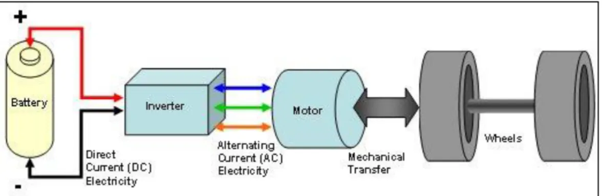
Fig 1.1 a HEV drive system
Figure 1.1 shows diagram of an electric drive system, where the inverter is fed direct current (DC) from the battery and converts it to alternating current (AC) and sends it to the motor. The electric motor uses this to create torque to power the wheels for propulsion. This shows a modern application of inverter and power electronics.
The expression for the rotor current of an induction motor at is given by
At the time of starting, the value of slip is very high, hence the starting current is very high. This kind of high starting current is very much detrimental for the machine since the machine windings are designed mainly to carry the rated currents. So to reduce this starting current manual starters are used like direct online, star delta and autotransformer.
AC motor starters which uses power semiconductors are being increasingly used to replace mechanical line starters and conventional reduced voltage starters. This is because of their controlled soft starting capability with lower starting current during the soft start period.
𝐼2𝑆=𝑅 𝑠𝐸20
NATIONAL INSTITUTE OF TECHNOLOGY,ROURKELA 3
Of these soft starters which apply reduced voltage to the motors are cheap, simple and reliable and occupy less volume and hence are a practicable solution to the starting problem of medium voltage large AC motors in applications where the starting torque requirement of the load is not excessively high.
Soft starter is an electrical device specializes with controlling AC motor with soft start, soft point, light-load energy saving and a good deal more protection features. The soft starters work on the principle that by controlling the firing angle of the solid state switches the voltage applied to the motor is varied.
Fuzzy Logic Controller has found various applications in the past decade. It has proved to be effective for complex, nonlinear and imprecisely defined process for which standard model based control techniques are impractical and impossible. Fuzzy Logic deals with problems which have vagueness, uncertainty and uses membership functions with values varying from 0 to 1.
1.2
MOTIVATION
Electrical machines are a very important part of Electrical Engineering and applications of machines in electric drives make them much more interesting. The current of an induction motor can go above its rated value at the time of fault or at the time of starting. Obviously whenever the fault takes place it is not in our hand or rather it is inpredictable. But during starting the current will go high and can be controlled. Hence to design a simple controller which can limit this starting current is the main aim of the project.
1.3
OBJECTIVE OF THESIS
The main objective of the thesis is to limit the starting current of the motor to three times the rated value. Also it is required to formulate proper rules to design a fuzzy logic controller which would limit the starting current to three times the rated value.
1.4
THESIS ORGANIZATION
Chapter 1 deals with the introduction, motivation and the objective of the thesis. Chapter 2 deals with Literature Review.
NATIONAL INSTITUTE OF TECHNOLOGY,ROURKELA 4
Also its applications are discussed here.
Chapter 4 deals with Fuzzy Logic Controller and its design. Here the rules are discussed and why these rules have been made are also designed.
Chapter 5 mainly deals with the block diagram of the overall system, filter design and as to how the control strategy is implemented.
Chapter 6 deals with simulation and results. Here all the waveforms are given for the simulated system for both open loop and closed loop.
Chapter 7 deals with conclusion and scope for future work.
NATIONAL INSTITUTE OF TECHNOLOGY,ROURKELA 5
CHAPTER 2
NATIONAL INSTITUTE OF TECHNOLOGY,ROURKELA 6
Literature Review
Direct Online starting may create problems when the ac supply is weak because it may cause low voltage at the starting which is a constraint as during starting too much reduction in voltage is detrimental. [5].
An uncontrolled start may cause a functioning of the overvoltage or under voltage relay, resulting in starting failure. Further the motor cannot be energized until it cools down to an allowable temperature in a long time period. Thus the current and torque profiles of the machine are to be tailored properly depending upon the load [5] [6].
AC Motor starters incorporating power semiconductor devices are used increasingly these days, putting back the conventional reduced voltage starters because of their controlled soft start capability with limited starting current. Among these thyristor-based soft starters which employ reduced voltage to the motors are of low cost, reliable and occupy lesser volume and hence are feasible solution for starting medium voltage large ac motors in applications where the starting torque requirement of the load is not so high [1].
Depending upon the initial switching instants of all the three phases to the supply, an induction machine may produce severe pulsations on the electromagnetic torque, regardless of whether it is regulated with direct online or soft starter [1].
When an ac induction motor is run at less than full load conditions, it consumes more energy to perform work. This excess energy is thrown off by the machine in the form of heat. With fuzzy logic controller, it is possible to control the peak amplitude of starting current and also save more energy during this starting period. In addition to this the cost and complexity of controller is reduced when it is designed using fuzzy logic method because it doesnot require the exact mathematical model of the system [8].
Soft start schemes show that gradual increase across the motor so that rated voltage will be applied across the motor at the end of soft start, thus increasing stator copper loss and undesirable harmonics to least at light loads. It was studied that efficiency was low and power factor was poor in that kind of soft starters under no load and light load conditions [9,10,11]. Sometimes the drive system lead to undesirable oscillations [12]. The novel soft start schemes reported in [13] have eliminated the above problems of the conventional soft starts and they
NATIONAL INSTITUTE OF TECHNOLOGY,ROURKELA 7
apply close to optimal voltage at the end of soft start, thus maintaining high efficiency better power factor and reduced copper loss.
In the proposed scheme the main focus is that by controlling the torque of the machine, the starting current is to be limited during the soft starting period. The induction machine is fed through an inverter. To reduce the current during starting, the voltage applied to the stator of the machine needs to slowly increased to rated value. This can be achieved by controlling the modulation index of the inverter. This kind of proposed scheme can be used in hybrid electric vehicles.
NATIONAL INSTITUTE OF TECHNOLOGY,ROURKELA 8
CHAPTER 3
3.1 Soft Starting
3.2 Types of Soft Starters
3.3 How Soft Starting helps to protect motors
3.4 Applications of Soft Starting
NATIONAL INSTITUTE OF TECHNOLOGY,ROURKELA 9
3.1 Soft Starting
Soft starters are electrical device which can control the AC motor in soft starting, soft stopping, light-load energy saving and for additional protection options. The soft starter's main components include three phase antiparallel thyristors between power source and the AC motor and related control circuits. The soft starters work on the principle that by controlling the firing angle of the solid state switches like thyristors, IGBT’s, Mosfets the voltage applied to the motor is varied. Therefore the main motive is elimination of mechanical starters like star delta, autotransformer and direct online starters.
3.2 Types of Soft Starters
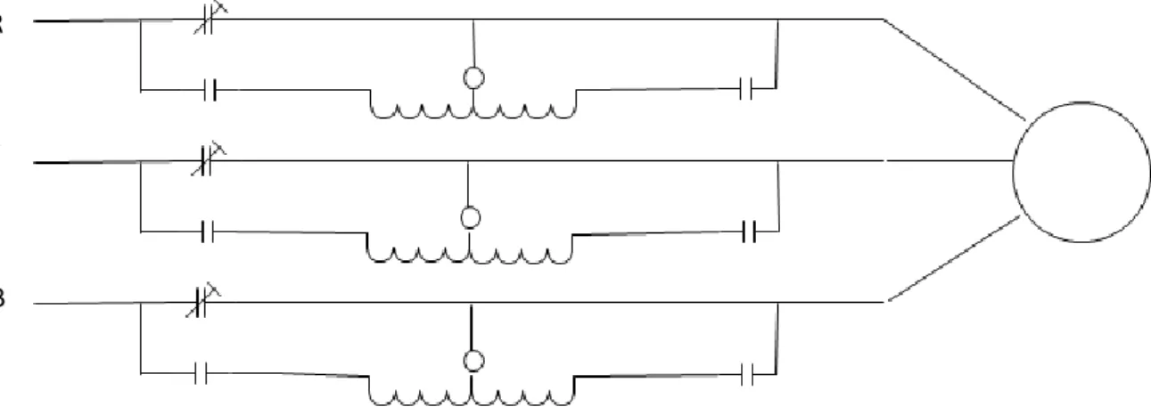
3.2.1 Primary Resistor Startup
This is one of the simple techniques which were used earlier. When the motor is started, the resistors resist the current flow leading to a drop in voltage. A timer is present which closes a group of contacts once the motor has accelerated to a pre-determined point. This removes the resistors from the circuit and lets full power go through to the motor. The main disadvantage is that there will be copper losses in the resistances.
Fig 3.1 Typical Electric Diagram for primary resistor reduced voltage starter
R
Y
B
NATIONAL INSTITUTE OF TECHNOLOGY,ROURKELA 10
3.2.2 Auto-Transformer Startup
Auto transformer starting is also a traditional method of soft starting. It is preferred over primary resistor starting when the starting current to be drawn from the line is minimum, but maximum starting torque per line current is required. Instead of using resistors, this starter uses taps on the transformer windings to control the power supply to the motor. Taps are usually set up to provide 80%, 65% and 50% of the line voltage, respectively and hence the voltage applied to the motor can be varied.
These taps give flexibility to the system. In Fig. 3.2 the motor is receiving voltage through the second of the three taps.
Starting current in autotransformer starter is less than DOL starter but the starting torque of autotransformer starter is low compared to DOL starter.
Fig 3.2 Typical Electrical Diagram for an autotransformer reduced voltage starter
3.2.3 Wye Delta
In case of star delta starter at the starting the motor is connected in star and after some time it is converted to delta using some switch. Obviously this transition will give a jerk to the machine and that can be harmful. Actually contactors are present which help during transiton. During starting in star connection lesser voltage is impressed to the stator of the machine and hence
R
Y
NATIONAL INSTITUTE OF TECHNOLOGY,ROURKELA 11
starting current will be low. In delta full voltage is impressed to the motor windings and hence the machine achieves full speed. Starting current in case of star delta starter is one third that of DOL starter whereas starting torque of star delta starter is one third that of DOL starter.
NATIONAL INSTITUTE OF TECHNOLOGY,ROURKELA 12
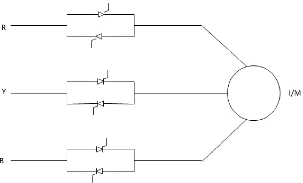
3.2.4 Solid State
The latest use of solid state devices such as thyristors (SCR), IGBTs, Mosfets are used for soft starting purpose. It eliminates mechanical components with electrical components. When the motor accelerates, this device controls motor voltage, current and torque. Fig. 3.4 shows how the solid state soft starter controls the current drawn and the starting torque. The SCR has the capability to rapidly switch heavy currents. This allows the soft starter to provide smooth stepless acceleration - the smoothest of any of the soft start methods. It is used for constant speed induction motors where the stator voltage is applied gradually to limit the starting current. As seen in the figure there are two thyristors in each phase connected in antiparallel.
Fig 3.4 Solid State Reduced Voltage Starter
3.3 How soft starters protect the motor ?
Soft Starters help to reduce overheating
They also help to know whether there is any phase loss in the motor. This is very helpful because any loss of phase will lead to tremendous unbalance in the system.
Current controllers are present in soft starting schemes which help in overload protection.
R
Y
B
NATIONAL INSTITUTE OF TECHNOLOGY,ROURKELA 13
3.4 Applications of Soft Starter:
They can be used for high inertia loads successfully.
They can be used to start pump with grid then switch to generator to avoid starting current.
They are used in variable speed drives nowadays.
NATIONAL INSTITUTE OF TECHNOLOGY,ROURKELA 14
CHAPTER 4
4.1 Introduction
4.2 Configuration of FLC
4.3 Steps to design a FLC
4.4 Designing of Fuzzy Logic Controller
4.5 Selecting and Designing Membership Functions
4.6 Rule Base
4.7 Summary
FUZZY LOGIC CONTROLLER AND ITS
DESIGN
NATIONAL INSTITUTE OF TECHNOLOGY,ROURKELA 15
4.1 Introduction
Fuzzy control is a control system based on AI is defined as intelligent control. A fuzzy control system essentially takes the experience and intuition of some human plant operator and sometimes those of a designer or researcher of a plant. The mathematical model of the plant is not required in fuzzy control. It is an adaptive and nonlinear control and gives robust performance for both linear and nonlinear plants with parameter variation. It is also easy to implement.
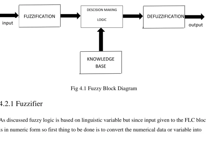
4.2 Configuration of FLC
Principal components of Fuzzy Logic Controller 1. Fuzzification Block or Fuzzifier
2. Knowledge base
3. Descision Making Block
4. Defuzzification block or Defuzzifier
Fig 4.1 Fuzzy Block Diagram
4.2.1 Fuzzifier
As discussed fuzzy logic is based on linguistic variable but since input given to the FLC block is in numeric form so first thing to be done is to convert the numerical data or variable into
FUZZIFICATION DESCISION MAKING LOGIC DEFUZZIFICATION KNOWLEDGE BASE input output
NATIONAL INSTITUTE OF TECHNOLOGY,ROURKELA 16
linguistic variable and this task is performed by the fuzzifier. So fuzzifier converts the numerical variable given to the FLC into linguistic variable. This fuzzification task includes choosing proper membership functions for the variables so that the crisp inputs can be converted into fuzzy sets.
4.2.2 Knowledge Base
It consists of data base and rule base. The main aim of data base is to provide necessary definations needed to define the linguistic control rules and the aim of rule base is to charecterize the control goals and policies by using a set of linguistic or then rules. In the If-then statement, the if part is called antecedent and the If-then part is called consequence.
4.2.3 Descision Making Block
It is the most important block of a fuzzy controller because it is the block that decides the output depending on the input. Based on fuzzy concepts, data and rule bases,it provides reasonable outputs.
4.2.4 Defuzzifier
It performs the task just opposite to that of a fuzzifier. So the task of the defuzzifier is to convert the linguistic variable into a crisp one. There are different types of defuzzification techniques present for defuzzification.
1. Centroid of Area(COA) 2. Bisector of Area(BOA) 3. Mean of Maximum(MOM) 4. Smallest of Minimum(SOM) 5. Largest of Maximum(LOM)
In our control design centroid of area technique is used for defuzzification.
4.3 Steps to design a Fuzzy Logic Controller
So the steps to design a fuzzy logic controller are as follows 1. Selecting the input to the FLC
NATIONAL INSTITUTE OF TECHNOLOGY,ROURKELA 17
2. Selecting proper MFs both for input and output variables 3. Fuzzification of the input variables
4. Preparing a fuzzy rule base for the controller 5. Selecting proper defuzzification technique
6. Defuzzification of output that is to be given to the system for desired operation
4.4 Designing of Fuzzy Logic Controller
The input to the fuzzy logic controller is the error between the currents in dc form. The three phase currents are converted into two phase currents and then the maginitude is taken. This is then converted into per unit by dividing with the rated current as shown below. This is the compared with one to get the error. The error is fed to the fuzzy logic controller. The output of the fuzzy logic controller is converted from dq to abc to get the three reference sinusoid, which is compared with carrier wave to generate the pulses to be fed to the inverter.
Fig 4.2 Block Diagram of control circuit
F
Divide by
rated current
FUZZY LOGIC CONTROLLER UZZY LOGIC CONTROLLER 𝑖𝛼2 + 𝑖𝛽2Compare with
1
Divide by rated
current
FUZZY LOGIC CONTROLLERDq to abc
Error
NATIONAL INSTITUTE OF TECHNOLOGY,ROURKELA 18
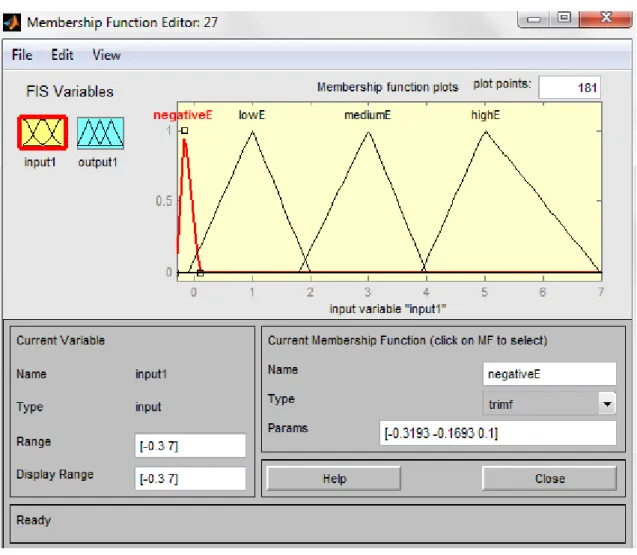
4.5 Selecting and Designing Membership functions
Fuzzy Set
Range of MFs
Membership Function
chosen
NegativeE(error) -0.3193 to -0.1693 -0.1693 to 0.1 Triangular LowE(error) -0.1 to 1 1 to 2 Triangular MediumE(error) 1.8 to 3 3 to 4 Triangular HighE(error) 3.9 to 5 5 to 7 TriangularTable 4.1 Fuzzy Set and MFs for input current error
NATIONAL INSTITUTE OF TECHNOLOGY,ROURKELA 19
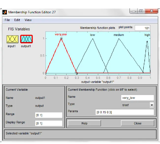
Fuzzy Set
Range of MFs
Membership Function
chosen
Very Low 0 to 0.15 0.15 to 0.3 Triangular Low 0.28 to 0.45 0..45 to 0.6 Triangular Medium 0.55 to 0.7 0.7 to 0.94 Triangular High 0.93 to 0.97 0.97 to 1 TriangularTable 4.2 Fuzzy Set and MFs for output
NATIONAL INSTITUTE OF TECHNOLOGY,ROURKELA 20
4.5 Rule Base
The rules that are incorporated in the Fuzzy Logic Controller are as follows
If input is negativeE then output is high
If input is lowE then output is medium.
If input is mediumE then output is low
If input is highE the output is very low
The main aim over here is that by seeing the error profile in the open loop system we have incorporated the above set of rules.
NATIONAL INSTITUTE OF TECHNOLOGY,ROURKELA 21
Fig 4.6 Error in current
We have decided that when the error is negative, we have set the modulation index around 0.95. When the error is one to two times we have set the modulation index to 0.7.When the error is two to four times we have set the modulation index to 0.4.When the error is four to seven times we have set the modulation index to 0.15. This is the main basis upon which the Fuzzy Logic Controller was designed and the values were taken care of accordingly.
4.6 Summary
In this chapter the control strategy as to how to implement the fuzzy logic controller is discussed. The logic behind the rules are also explained.
0 0.1 0.2 0.3 0.4 0.5 -2 0 2 4 6 8 Time(sec) E rr o r
NATIONAL INSTITUTE OF TECHNOLOGY,ROURKELA 22
CHAPTER 5
5.1
Introduction
5.2
Low pass filter design
5.3
Block diagram
5.4
Control strategy
5.5
Summary
FUZZY LOGIC BASED SOFT STARTING
OF INDUCTION MOTOR WITH CURRENT
NATIONAL INSTITUTE OF TECHNOLOGY,ROURKELA 23
5.1
INTRODUCTION
The inverter output contains square wave. It has harmonics which needs to be eliminated from the system. For this purpose a Low Pass Filter is used which allows lower order harmonics to pass through and higher order harmonics to be eliminated. This contains an inductor in series and a capacitance in shunt. A small amount of resistance cannot be neglected. It is important aspect that the filter designed should not cause loading effect to the induction machine. Hence its design is an important aspect.
In this chapter a strategy is shown in which the starting current is limited. The induction motor is fed through an inverter. The inverter is switched through sinusoidal pulse width modulation technique. The output of the inverter is filtered using a low pass filter. This is then fed to an induction motor. The three phase currents are then converted into two phase currents using transformations. The magnitude of this two phase current is taken and converted to per unit. It is then passed through a fuzzy logic controller (FLC) controller after comparing with a reference value. Finally the FLC output is averaged and then converted from dq to abc. Thus by controlling the amplitude of reference wave the inverter output is controlled and hence the starting current is limited.
NATIONAL INSTITUTE OF TECHNOLOGY,ROURKELA 24
MACHINE SPECIFICATIONS
Rated Power 5.4HP, 4KW Rated Voltage 400 V Rated Frequency 50Hz Rated Speed 1430 rpmType of Rotor Squirrel Cage type No of Poles 4 𝑅𝑠 1.405 Ω 𝐿𝑙𝑠 0.005839 H 𝐿𝑚 0.1722 H 𝑅𝑟᾽ 1.395 Ω 𝐿𝑙𝑟᾽ 0.005839 H Rated Torque 25.46 Nm Rated Current 10.9 amp Rated Speed 157 rad/sec
Table 5.1 Machine Specifications
5.2 L-C filter design
For the design of the filter, the Fast Fourier Transform of the line voltage was taken, where the frequencies were seen and the contribution of the harmonics. The important factor to be kept in mind while designing the L-C filter is resonance. We have to choose the resonating frequency in such a way so that the contribution of harmonics is low or else it will be amplified and affect the invertor voltage.
NATIONAL INSTITUTE OF TECHNOLOGY,ROURKELA 25
Fig 5.1 Equivalent Circuit of the filter
To avoid the loading effect the impedence seen along AB should be much smaller than the minimum load that we can connect.
𝑍𝐴𝐵 = 𝑋𝐿∗𝑋𝐶 𝑋𝐿 +𝑋𝐶 = 𝑍𝐿𝑚𝑖𝑛 10 𝑍𝐿𝑚𝑖𝑛 =(𝑅𝑠+ 𝑅𝑟᾽) + j( 𝑋𝑙𝑠+𝑋𝑙𝑟᾽) At resonance 𝑋𝐿 = 𝑋𝐶
where 𝑍𝐴𝐵 is the impedence seen along A and B,
𝑋𝐿 is the inductive reactance,
𝑋𝐶 is the capacitative reactance,
𝑅𝑠 is the stator resistance, 𝑅𝑟᾽ is the rotor resistance,
𝑋𝑙𝑠 is the stator leakage reactance,
𝑋𝑙𝑟᾽ is the rotor leakage reactance and
𝑍𝐿𝑚𝑖𝑛 is the minimum impedence as seen from A and B.
Considering resonance to occur at 1350 Hz the values of L and C were computed and found out to be L=1.459 mH ,C=9.52 μF.
A
NATIONAL INSTITUTE OF TECHNOLOGY,ROURKELA 26
5.3 Fast Fourier Transform of line voltage
Fig 5.2 FFT of line voltage
The Fast Fourier Transform (FFT) of the line voltage is taken and the order of harmonics is seen and their corresponding magnitude. This is significant for the L-C filter design because there will be resonance and we need to choose proper resonating frequency so that at resonance the contribution of harmonics should be low or else it would be amplified to around ten times. In this chapter the LC low pass filter is designed. The values of L and C are found to be L=1.459 mH ,C=9.52 μF. The three phase inverter output is filtered corresponding ac output voltage is obtained which is nearly a sine wave. This filtered output is connected to the induction machine. 0 1 2 3 4 5 6 7 8 9 10 x 105 0 200 400 600 800 1000 order of harmonics m ag ni tu de 0 50 100 150 200 250 300 350 400 0 10 20 30 order of harmonics m ag ni tu de ZOOM
NATIONAL INSTITUTE OF TECHNOLOGY,ROURKELA 27
Fig 5.3 System scenario with LC filter
5.4 BLOCK DIAGRAM
𝑖
𝑎𝑏𝑐𝑖
𝛼𝛽𝒊
𝒓𝒆𝒇𝑖
𝛼2+ 𝑖
𝛽2 Sinusoidal PWMBridge
Inverter
Low
Pass
Filter
Induction
Motor
Fuzzy Logic Controllerabc
dq
NATIONAL INSTITUTE OF TECHNOLOGY,ROURKELA 28
Fig 5.4 Block Diagram of SIMULINK MODEL
5.5 CONTROL STRATEGY
Fig 1 shows the schematic of the proposed model. The main aim here is to reduce the voltage applied to the stator during the starting few seconds. For that purpose we need to control the amplitude of the sinusoid. We have used sinusoidal pulse width modulation (spwm) technique for generating the pulses for the six inverter switches. In case of spwm technique we know,
𝑚𝑎 = 𝑣𝑐𝑜𝑛𝑡𝑟𝑜𝑙
𝑣𝑡𝑟𝑖
𝑚𝑓 = 𝑓𝑠
𝑓
where 𝑚𝑎is the amplitude modulation ratio, 𝑣𝑐𝑜𝑛𝑡𝑟𝑜𝑙 is the magnitude of control voltage i.e the sinusoid, 𝑣𝑡𝑟𝑖 is the magnitude of triangular wave, 𝑚𝑓 is the frequency modulation ratio, 𝑓𝑠 is the switching frequency, 𝑓 is the supply frequency.
For an inverter the expression of phase voltage is given by
𝑣𝐴0 = 𝑣𝑐𝑜𝑛𝑡𝑟𝑜𝑙
𝑣𝑡𝑟𝑖
𝑉𝑑
2
= 𝑚𝑎𝑉2𝑑
Where 𝑉𝑑 is the dc link voltage of the inverter. Hence it is seen the output voltage of the inverter is directly proportional to the control voltage. Hence my controlling the amplitude of the sinusoid, the control was possible.
The inverter output is filtered with a L-C low pass filter. This is then applied to the specified Induction Motor. The three phase stator currents are converted to two phase with the following relation, 𝑖𝛼= 2 3𝑖𝑎− 1 3𝑖𝑏− 1 3𝑖𝑐 𝑖𝛽 = − 1 √3𝑖𝑏+ 1 √3𝑖𝑐
NATIONAL INSTITUTE OF TECHNOLOGY,ROURKELA 29
The magnitude of this current i.e 𝑖𝛼2+ 𝑖𝛽2 is calculated which is nothing but the dc form of the stator current. It is then converted into per unit(pu). This is then compared with the rated value. This error is then passed through a Fuzzy Logic Controller(FLC). Moving average of the output of the FLC is taken. It is then converted from dq to abc. Hence by controlling the amplitude of the control voltage, the inverter output voltage is controlled. Hence the starting current is controlled.
5.6 SUMMARY
In this chapter, the main control strategy is discussed. The block diagram depicts the main procedure in which it is implemented. By adopting such strategy it is possible to eliminate mechanical starters like DOL, Star Delta and Autotransformer starters. This kind of scalar control technique can be easily implemented and use of fuzzy logic controller increases the adaptive capability of the system.
NATIONAL INSTITUTE OF TECHNOLOGY,ROURKELA 30
CHAPTER 6
6.1 Machine Specifications and System Parameters
6.2 Performance of system without FLC
6.3 Performance of system with FLC
6.4 Comparisn of system in open loop and closed loop
6.5 Summary
NATIONAL INSTITUTE OF TECHNOLOGY,ROURKELA 31
6.1 MACHINE SPECIFICATIONS AND SYSTEM
PARAMETERS
Machine Specifications
Rated Power 5.4HP, 4KW Rated Voltage 400 V Rated Frequency 50Hz Rated Speed 1430 rpmType of Rotor Squirrel Cage type No of Poles 4 𝑅𝑠 1.405 Ω 𝐿𝑙𝑠 0.005839 H 𝐿𝑚 0.1722 H 𝑅𝑟᾽ 1.395 Ω 𝐿𝑙𝑟᾽ 0.005839 H Rated Torque 25.46 Nm Rated Current 10.9 amp Rated Speed 157 rad/sec
System Parameters
The switching frequency is 25KHz.
The load torque is assumed to be in the form
𝑇𝐿 = 𝑇𝑏[0.1𝑆(𝜔𝑟𝑚) + 0.9(𝜔𝑟𝑚
𝜔𝑏𝑚)2]
The dc input to the inverter is 800* 23
NATIONAL INSTITUTE OF TECHNOLOGY,ROURKELA 32
6.2 PERFORMANCE OF SYSTEM WITHOUT FUZZY
LOGIC CONTROLLER (OPEN LOOP)
Fig 6.1 Open Loop Load Torque profile
Fig 6.2 Open Loop Rotor Speed profile
0 0.1 0.2 0.3 0.4 0.5 -10 0 10 20 30 Time(sec) L o a d T o rq u e (N m ) 0 0.1 0.2 0.3 0.4 0.5 -50 0 50 100 150 200 Time(rad/sec) R o to r S p e e d (r a d /s e c )
NATIONAL INSTITUTE OF TECHNOLOGY,ROURKELA 33
Fig 6.3 Open Loop Stator Current profile
Fig 6.4 Open Loop Stator Voltage profile
Fig 6.5 Open Loop Electromagnetic Torque profile
0 0.1 0.2 0.3 0.4 0.5 -50 0 50 Time(sec) S ta to r C u rr e n t( a m p s ) 0 0.1 0.2 0.3 0.4 0.5 -400 -200 0 200 400 Time(sec) S ta to r v o lt a g e (v o lt s ) 0 0.1 0.2 0.3 0.4 0.5 -50 0 50 100 150 200 Time(sec) E le c tr o m a g n e ti c T o rq u e (N m )
NATIONAL INSTITUTE OF TECHNOLOGY,ROURKELA 34
Fig 6.6 Open Loop Error profile
The load applied to the squirrel cage induction motor is a fan type load.The waveform of which is shown above in Fig 6.1.At the steady state condition the load is around 24Nm. The rotot speed initially goes higher than the rated value at the transient condition but at steady state reaches 157 rad/sec,the rated speed of the machine as shown in Fig 6.2. The stator current initially for the first two cycles is very high around 85 amps as shown in Fig 6.3. The peak to peak value of filtered stator voltage is around 400 volts as shown in Fig 6.4. The Electromagnetic Torque developed by the machine is according to the load that is applied, but at the transient state the torque goes to a very high value as shown in Fig 6.5. The error profile is shown in Fig 6.6,it is the error between the rated current and actual current(dc) taken in per unit(pu).
6.3 PERFORMANCE OF SYSTEM WITH FUZZY LOGIC
CONTROLLER (FLC) (CLOSED LOOP)
Fig 6.7 Closed Loop Load Torque profile
0 0.1 0.2 0.3 0.4 0.5 -2 0 2 4 6 8 Time(sec) E rr o r 0 0.1 0.2 0.3 0.4 0.5 -10 0 10 20 30 Time(sec) To rq u e (N m )
NATIONAL INSTITUTE OF TECHNOLOGY,ROURKELA 35
Fig 6.8 Closed Loop Rotor Speed profile
Fig 6.9 Closed Loop Stator Current profile
Fig 6.10 Closed Loop Stator Voltage profile
0 0.1 0.2 0.3 0.4 0.5 -100 0 100 200 Time(sec) R o to r S p e e d (r a d /s e c ) 0 0.1 0.2 0.3 0.4 0.5 -40 -20 0 20 40 Time(sec) S ta to r C u rr e n t( a m p s )
0
0.1
0.2
0.3
0.4
0.5
-500
0
500
Time(sec)
S ta to r V o lt a g e (v o lt s )NATIONAL INSTITUTE OF TECHNOLOGY,ROURKELA 36
Fig 6.11 Closed Loop Electromagnetic Torque profile
Fig 6.12 Closed Loop Averaged Fuzzy Logic Controller output profile
Fig 6.13 Closed Loop Reference Sinusoid profile
0
0.1
0.2
0.3
0.4
0.5
-20
0
20
40
60
Time(sec) D e v e lo p e d To rq u e (N m ) 0 0.1 0.2 0.3 0.4 0.5 0 0.2 0.4 0.6 0.8 1 Time(sec) FL C o u tp u t 0 0.1 0.2 0.3 0.4 0.5 -2 -1 0 1 2 Time(sec) R e fe re n c e w a v eNATIONAL INSTITUTE OF TECHNOLOGY,ROURKELA 37
Fig 6.7 shows the profile of load torque applied to the induction motor. It has got a steady state value of 24 Nm. The rotor speed profile is shown in Fig 6.8. It is seen that as compared to the open loop it takes much more time to reach steady state value of 157 rad/sec. the stator current profile is shown in Fig 6.9 where during the first few cycles the current goes to around 40amps i.e four times the rated value. Hence the starting current has been limited from 85amps to 40amps. The stator voltage variation is seen in Fig 6.10, where it can be seen that the voltage gradually increases in the starting period and then reaches the steady state after 0.1seconds. This mainly helps to reduce the starting current of the machine. The developed electromagnetic torque profile is seen in Fig 6.11 where there is a bit of oscillation mainly due to the fuzzy logic controller output. The fuzzy logic controller output is nothing but the modulation index. It is seen from Fig 6.12 that the output slowly increases from 0 to 0.9. This fuzzy logic controller output after conversion from dq to abc gives rise to the reference sine wave which is seen in Fig 6.13. It can be seen that the amplitude of this wave increases slowly to 1.
6.4 COMPARISN OF SYSTEM IN OPEN LOOP AND
CLOSED LOOP
OPEN LOOP
CLOSED LOOP
Starting Current
It is around 85amps and persists for three cycles.It is around 40amps and persists for two cycles.
Stator Voltage
Peak to peak voltage is around 400 volts from the starting.Peak to peak voltage slowly increases to 400 volts.
Rotor Speed
Initially the speed is high and goes to steady state value within 0.05seconds.The speed slowly increases to steady state value but takes much more time around 0.1 seconds.
NATIONAL INSTITUTE OF TECHNOLOGY,ROURKELA 38 2 *p i* 5 0 we 1 v1 0 v0 si n si n e D is cr e te , T s = 1 e -0 0 6 s . p o w e rg u i dq0 sin _c o s a b c dq 0_t o_a bc Tr an sfo rm at io n co s co s t T o W o rk sp a ce S ig n S co p e 7 S co p e 6 S co p e P ro d u ct 6 P ro d u ct 5 P ro d u ct 4 P ro d u ct 3 P ro d u ct 2 VR 1 VR 2 VR 3 PW M 1 PW M 3 PW M 5 P W M C ircu it VLL ILL VP Ia Ib Ic Oa Ob Oc M e a su re IG1 IG3 IG5 + v e -v e I1 I2 I3 IN V E R T E R FI1 FI2 FI3 F 01 F 02 F 03 F IL T E R D ivi d e 5 D C 0 .1 C o n st a n t6 2 5 .4 6 C o n st a n t5 157 C o n st a n t4 0 .9 C o n st a n t2 C lo ck m A B C Tm A syn ch ro n o u s M a ch in e S I U n its 1 A d d < St at or c urrent is _a (A)> < St at or c urrent is _a (A)> < St at or c urrent is _b (A)> < St at or c urrent is _b (A)> < St at or c urrent is _c (A)> < St at or c urrent is _c (A)> < R ot or s peed (w m )> < R ot or s peed (w m )> < Elec trom agnet ic t orque T e (N *m )> < Elec trom agnet ic t orque T e (N *m )>
OPEN LOOP SIMULATION DIAGRAM OF THE SYSTEM
NATIONAL INSTITUTE OF TECHNOLOGY,ROURKELA 39 2 *p i* 5 0 we 0 v0 si n si n e D is cr e te , T s = 1 e -0 0 6 s . p o w e rg u i dq0 sin _c o s a b c d q 0_t o _a b c T ra n sf o rm a tio n co s co s add t T o W o rk sp a ce sq rt S q rt S ig n S co p e P ro d u ct 6 P ro d u ct 5 P ro d u ct 4 P ro d u ct 3 P ro d u ct 2 P ro d u ct 1 P ro d u ct VR 1 VR 2 VR 3 PW M 1 PW M 3 PW M 5 P W M C ircu it VLL ILL VP Ia Ib Ic Oa Ob Oc M e a su re M e a n M e a n V a lue IG1 IG3 IG5 + v e -v e I1 I2 I3 IN V E R T E R K *u G a in F u zzy L o g ic C o n tro lle r FI1 FI2 FI3 F 01 F 02 F 03 F IL T E R D ivi d e 5 D ivi d e 3 D C 1 C o n st a n t7 0 .1 C o n sta n t6 2 5 .4 6 C o n st a n t5 157 C o n st a n t4 1 0 .9 C o n st a n t3 0 .9 C o n st a n t2 C lo ck m A B C Tm A syn ch ro n o u s M a ch in e S I U n its 1 A d d < St at or c urrent is _a (A)> < St at or c urrent is _a (A)> < St at or c urrent is _b (A)> < St at or c urrent is _b (A)> < St at or c urrent is _c (A)> < St at or c urrent is _c (A)> < R ot or s peed (w m )> < R ot or s peed (w m )> < Elec trom agnet ic t orque T e (N *m )> < Elec trom agnet ic t orque T e (N *m )>
CLOSED LOOP SIMULINK MODEL OF THE SYSTEM WITH
FUZZY LOGIC CONTROLLER
NATIONAL INSTITUTE OF TECHNOLOGY,ROURKELA 40
6.4 SUMMARY
In this chapter, the results of the simulation performed is shown. Both for open loop and closed loop. The Simulink diagram for open loop and closed loop is also given. A comparison has been made between the performance of the system with and without Fuzzy Logic Controller.
NATIONAL INSTITUTE OF TECHNOLOGY,ROURKELA 41
CHAPTER 7
7.1 Conclusion
7.2 Scope for future work
CONCLUSION AND SCOPE
FOR FUTURE WORK
NATIONAL INSTITUTE OF TECHNOLOGY,ROURKELA 42
7.1 CONCLUSION
The starting current of an induction motor is around eight to nine times. This high current persists for a few cycles. Since the windings of the machine are designed to carry maximum of rated current, this high current during starting is detrimental. Hence the aim of our project as based on this.
The main objective of the project was to limit the starting current of the induction machine without the use of mechanical starters and using soft starting technique. Fuzzy Logic Control is used and the starting current is limited to four times as compared to nine times in open loop.
7.2 SCOPE FOR FUTURE WORK
The work done so far is scalar control. The controller designed is simple and would be cheap. In future this kind of controller can be designed in hardware using microcontroller. Also vector control technique can be applied for better performance but that would make the system costly.
NATIONAL INSTITUTE OF TECHNOLOGY,ROURKELA 43
REFERENCES
[1] Ademir Nied, Jose de Oliveira, Rafael de Farias Campos, Rogerio Pinho Dias, and Luiz Carlos de Souza Marques,” Soft Starting of Induction Motor with Torque Control“, IEEE Transactions on Industry Applications, Vol. 46,No. 3,May/June 2010 .
[2]Y.A Chapuis, D.Roye ”Direct Torque Control and Current Limitation Method in Start Up of an Induction Motor”
[3] Sifat Shah, A.Rashid,MKL Bhatti “Direct Quadrature(D-Q) Modelling of 3-Phase Induction Motor using Matlab/Simulink” ,Canadian Journal on Electrical and Electronics Engineering Vol. 3,No. 5,May 2012.
[4] Gurkan Zenginobuz , Isik Cadirci, Muammer Ermis,and Cuneyt Barlak,“ Soft Starting of Large Induction Motors at constant current with Minimized Starting Torque Pulsations”,IEEE Transactions on Industry Applications, Vol. 37,No. 5,September/October 2001.
[5] J. Nevelsteen and H. Aragon, “Starting of large motors—Methods and economics,” IEEE
Trans. Ind. Applications, vol. 25, pp. 1012–1018,Nov./Dec. 1989.
[6] F. Blaabjerg, J. K. Pedersen, S. Rise, H. H. Hansen, and A. M. Trzynadlowski, “Can soft-starters help save energy,” IEEE Ind. Applications. Mag., vol. 3, pp. 56–66, Sept./Oct. 1997.
[7] Fin Haugen , Article “Zeigler Nicholas Closed Loop Method”,17 July 2010.
[8] Mr Hemanth Amhia, ” Analysis and Control of starting current of induction motor using fuzzy logic controller” IOSR Journal of Engineering(IOSERJEN)
[9]T.R. Gururaja Rao, "Smart Induction Motor Controller with Software Diagnostics", M.S.Thesis, IIT,Madras, 1989.
[10]G.Bhuvaneswari, "Intelligent Induction Motor Drive", Ph.D Thesis,IIT, Madras, 1992.
[11]G. Bhuvaneswari, V.V. Sastry, "Energy Efficient Solid-state Induction Motor
NATIONAL INSTITUTE OF TECHNOLOGY,ROURKELA 44
1991, Florence, Italy,R.S. Janardhana Iyengar, V.V. Sastry,
[12]R.S. Janardhana Iyengar, V.V. Sastry,"Oscillations in Voltage Controlled
Induction Motor Drives",International Conference on Power Electronics and Drive system PEDS'95, 21-24, February 1995, Singapore,pp 123-128.
[13]R. S. Janardhana Iyengar, "Novel Techniques for Energy Efficient Voltage Controlled Induction Motor DrivesIt, Ph.D Thesis submitted to IIT, Madras, May 1995.
[14] N Mohan, TM Underland, WP Robbins. “ Power electronics: converters, applications, and design. 3rd ed. John Wiley & sons: 2003