Citrix NetScaler VPX Getting Started
Guide
(SUCH AS TRANSLATION, TRANSFORMATION, OR ADAPTATION) WITHOUT THE EXPRESS WRITTEN PERMISSION OF CITRIX SYSTEMS, INC.
ALTHOUGH THE MATERIAL PRESENTED IN THIS DOCUMENT IS BELIEVED TO BE ACCURATE, IT IS PRESENTED WITHOUT WARRANTY OF ANY KIND, EXPRESS OR IMPLIED. USERS MUST TAKE ALL RESPONSIBILITY FOR THE USE OR APPLICATION OF THE PRODUCT(S) DESCRIBED IN THIS MANUAL. CITRIX SYSTEMS, INC. OR ITS SUPPLIERS DO NOT ASSUME ANY LIABILITY THAT MAY OCCUR DUE TO THE USE OR APPLICATION OF THE PRODUCT(S) DESCRIBED IN THIS DOCUMENT. INFORMATION IN THIS DOCUMENT IS SUBJECT TO CHANGE WITHOUT NOTICE. COMPANIES, NAMES, AND DATA USED IN EXAMPLES ARE FICTITIOUS UNLESS OTHERWISE NOTED.
The following information is for FCC compliance of Class A devices: This equipment has been tested and found to comply with the limits for a Class A digital device, pursuant to part 15 of the FCC rules. These limits are designed to provide reasonable protection against harmful interference when the equipment is operated in a commercial
environment. This equipment generates, uses, and can radiate radio-frequency energy and, if not installed and used in accordance with the instruction manual, may cause harmful interference to radio communications. Operation of this equipment in a residential area is likely to cause harmful interference, in which case users will be required to correct the interference at their own expense.
Modifying the equipment without Citrix' written authorization may result in the equipment no longer complying with FCC requirements for Class A digital devices. In that event, your right to use the equipment may be limited by FCC
regulations, and you may be required to correct any interference to radio or television communications at your own expense.
You can determine whether your equipment is causing interference by turning it off. If the interference stops, it was probably caused by the NetScaler Request Switch™ 9000 Series equipment. If the NetScaler equipment causes
interference, try to correct the interference by using one or more of the following measures: Move the NetScaler equipment to one side or the other of your equipment.
Move the NetScaler equipment farther away from your equipment.
Plug the NetScaler equipment into an outlet on a different circuit from your equipment. (Make sure the NetScaler equipment and your equipment are on circuits controlled by different circuit breakers or fuses.)
Modifications to this product not authorized by Citrix Systems, Inc., could void the FCC approval and negate your authority to operate the product.
BroadCom is a registered trademark of BroadCom Corporation. Fast Ramp, NetScaler, and NetScaler Request Switch are trademarks of Citrix Systems, Inc. Linux is a registered trademark of Linus Torvalds. Internet Explorer, Microsoft, PowerPoint, Windows and Windows product names such as Windows NT are trademarks or registered trademarks of the Microsoft Corporation. NetScape is a registered trademark of Netscape Communications Corporation. Red Hat is a trademark of Red Hat, Inc. Sun and Sun Microsystems are registered trademarks of Sun Microsystems, Inc. Other brand and product names may be registered trademarks or trademarks of their respective holders.
Software covered by the following third party copyrights may be included with this product and will also be subject to the software license agreement: Copyright 1998 © Carnegie Mellon University. All rights reserved. Copyright © David L.
Mills 1993, 1994. Copyright © 1992, 1993, 1994, 1997 Henry Spencer. Copyright © Jean-loup Gailly and Mark Adler.
Copyright © 1999, 2000 by Jef Poskanzer. All rights reserved. Copyright © Markus Friedl, Theo de Raadt, Niels Provos,
Dug Song, Aaron Campbell, Damien Miller, Kevin Steves. All rights reserved. Copyright © 1982, 1985, 1986,
1988-1991, 1993 Regents of the University of California. All rights reserved. Copyright © 1995 Tatu Ylonen, Espoo,
Finland. All rights reserved. Copyright © UNIX System Laboratories, Inc. Copyright © 2001 Mark R V Murray. Copyright
1995-1998 © Eric Young. Copyright © 1995,1996,1997,1998. Lars Fenneberg. Copyright © 1992. Livingston
Enterprises, Inc. Copyright © 1992, 1993, 1994, 1995. The Regents of the University of Michigan and Merit Network,
Inc. Copyright © 1991-2, RSA Data Security, Inc. Created 1991. Copyright © 1998 Juniper Networks, Inc. All rights
reserved. Copyright © 2001, 2002 Networks Associates Technology, Inc. All rights reserved. Copyright (c) 2002
Networks Associates Technology, Inc. Copyright 1999-2001© The Open LDAP Foundation. All Rights Reserved.
Copyright © 1999 Andrzej Bialecki. All rights reserved. Copyright © 2000 The Apache Software Foundation. All rights
reserved. Copyright (C) 2001-2003 Robert A. van Engelen, Genivia inc. All Rights Reserved. Copyright (c) 1997-2004 University of Cambridge. All rights reserved. Copyright (c) 1995. David Greenman. Copyright (c) 2001 Jonathan Lemon. All rights reserved. Copyright (c) 1997, 1998, 1999. Bill Paul. All rights reserved. Copyright (c) 1994-1997 Matt Thomas.
All rights reserved. Copyright © 2000 Jason L. Wright. Copyright © 2000 Theo de Raadt. Copyright © 2001 Patrik
Lindergren. All rights reserved.
Last Updated: January 2011
Contents
Preface...11
Formatting Conventions for NetScaler Documentation . . . .11
Documentation Available on the NetScaler Appliance . . . 12
Getting Service and Support . . . 13
NetScaler Documentation Feedback . . . .13
1 Citrix NetScaler VPX Overview...15
NetScaler VPX Setup for the XenServer Platform. . . 16
XenServer. . . 16
XenCenter. . . .17
Command Center. . . 17
NetScaler VPX Setup for the VMware ESX Platform. . . 18
2 Understanding the NetScaler...19
Switching Features. . . .20
Security and Protection Features. . . .20
Optimization Features. . . .20
Where Does a NetScaler Fit in the Network?. . . 20
Physical Deployment Modes. . . .21
Citrix NetScaler as an L2 Device. . . 22
Citrix NetScaler as a Packet Forwarding Device. . . .22
How a NetScaler Communicates with Clients and Servers. . . .22
Understanding NetScaler-Owned IP Addresses. . . 23
How Traffic Flows Are Managed. . . .24
Traffic Management Building Blocks. . . 25
A Simple Load Balancing Configuration. . . .25
Understanding Virtual Servers. . . .26
Understanding Services. . . .28
Understanding Policies and Expressions. . . .29
Prerequisites for Installing NetScaler Virtual Appliances on XenServer. . . .32
XenServer Hardware Requirements. . . .32
XenCenter System Requirements. . . .33
Installing NetScaler Virtual Appliances on XenServer by Using XenCenter. . . .34
4 Installing NetScaler Virtual Appliances on VMware ESX. . . .37
Prerequisites for Installing NetScaler Virtual Appliances on VMware. . . .38
VMware ESX Hardware Requirements. . . .38
VMware vSphere Client 4.0 System Requirements. . . .40
OVF Tool 1.0 System Requirements. . . .40
Downloading the NetScaler VPX Setup Files. . . .41
Labeling the Physical Network Ports of VMware ESX. . . .41
Installing NetScaler Virtual Appliances on VMware ESX 4.0. . . .42
To install NetScaler virtual appliances on VMware ESX 4.0 by using VMware vSphere Client. . . .42
Installing NetScaler Virtual Appliances on VMware ESX 3.5. . . .42
To install NetScaler virtual appliances on VMware ESX 3.5 by using the VMware OVF Tool. . . .43
5 Configuring the Basic System Settings...45
Setting Up the Initial Configuration by Using the NetScaler VPX Console. . . .46
To configure the initial settings on the virtual appliance through the VPX Console by using the management application. . . .46
Configuring NetScaler VPX by Using the Command-Line Interface. . . .47
To complete initial configuration by using the NetScaler command line. . . .47
Configuring NetScaler VPX by Using the Configuration Utility. . . .47
To configure initial settings by using the configuration utility. . . .48
6 Understanding Common Network Topologies...49
Setting Up Common Two-Arm Topologies. . . .50
Setting Up a Simple Two-Arm Multiple Subnet Topology. . . .50
Setting Up a Simple Two-Arm Transparent Topology. . . .51
Setting Up Common One-Arm Topologies. . . .52
Setting Up a Simple One-Arm Single Subnet Topology. . . .52
Setting Up a Simple One-Arm Multiple Subnet Topology. . . .53
7 Configuring System Management Settings...55
To configure HTTP parameters by using the configuration utility. . . .58
To set the FTP port range by using the configuration utility. . . .59
Configuring Modes of Packet Forwarding. . . .59
Enabling and Disabling Layer 2 Mode. . . .60
To enable or disable Layer 2 mode by using the NetScaler command line. . . .61
To enable or disable Layer 2 mode by using the configuration utility. . . .61
Enabling and Disabling Layer 3 Mode. . . .62
To enable or disable Layer 3 mode by using the NetScaler command line. . . .62
To enable or disable Layer 3 mode by using the configuration utility. . . .63
Enabling and Disabling MAC-Based Forwarding Mode. . . .63
To enable or disable MAC-based forwarding by using the NetScaler command line. . . .65
To enable or disable MAC-based forwarding by using the configuration utility . . . .66
Configuring Network Interfaces. . . .66
Virtual LANs. . . .66
Link Aggregate Channels. . . .67
Modifying Network Interfaces. . . .67
To modify a network interface by using the NetScaler command line. . . .67
To modify a network interface by using the configuration utility. . . .68
Monitoring Network Interfaces. . . .68
To display the statistics of a network interface by using the NetScaler command line. . . .68
To display the statistics of a network interface by using the configuration utility . . . .70
Configuring a VLAN. . . .70
To configure a VLAN by using the NetScaler command line. . . .70
To configure a VLAN by using the configuration utility. . . .71
Viewing the Statistics of a VLAN. . . .71
To view the statistics of a VLAN by using the NetScaler command line. . . .71
To view the statistics of a VLAN by using the configuration utility. . . .71
Configuring Link Aggregate Channels. . . .72
To configure a link aggregate channel by using the NetScaler command line . . . .72
To configure a link aggregate channel by using the configuration utility. . . .73
Configuring Clock Synchronization. . . .73
To configure clock synchronization on your NetScaler. . . .73
Configuring DNS. . . .74 Citrix NetScaler VPX Getting Started Guide
To add a name server by using the configuration utility. . . .75
Configuring SNMP. . . .75
Adding SNMP Managers. . . .77
To add an SNMP manager by using the NetScaler command line. . . .77
To add an SNMP manager by using the configuration utility. . . .77
Adding SNMP Traps Listeners. . . .77
To add an SNMP trap listener by using the NetScaler command line. . . .78
To add an SNMP trap listener by using the configuration utility. . . .78
Configuring SNMP Alarms. . . .78
To enable or disable an alarm by using the NetScaler command line. . . .79
To set the severity of the alarm by using the NetScaler command line. . . .79
To configure alarms by using the configuration utility. . . .79
Configuring Syslog. . . .80
Verifying the Configuration. . . .80
8 Load Balancing Traffic on a NetScaler...85
How Load Balancing Works. . . .86
Configuring Load Balancing. . . .87
Enabling Load Balancing. . . .89
To enable load balancing by using the NetScaler command line. . . .89
To enable load balancing by using the configuration utility. . . .89
Configuring Services and a Vserver. . . .89
To implement the initial load balancing configuration by using the NetScaler command line. . . .90
To implement the initial load balancing configuration by using the configuration utility. . . .90
Choosing and Configuring Persistence Settings . . . .90
Configuring Persistence Based on Cookies. . . .92
Configuring Persistence Based on Server IDs in URLs. . . .94
Configuring Features to Protect the Load Balancing Configuration. . . .95
Configuring URL Redirection. . . .95
Configuring Backup Vservers. . . .96
A Typical Load Balancing Scenario. . . .98
9 Accelerating Load Balanced Traffic by Using Compression...103
Compression Configuration Task Sequence. . . .104
Enabling Compression. . . .104
To enable compression by using the NetScaler command line. . . .105
Configuring Services to Compress Data. . . .105
To enable compression on a service by using the NetScaler command line. . . .106
To enable compression on a service by using the configuration utility. . . .107
Binding a Compression Policy to a Virtual Server. . . .107
To bind or unbind a compression policy to a virtual server by using the NetScaler command line. . . .107
To bind or unbind a compression policy to a load balancing virtual server by using the configuration utility. . . .108
10 Securing Load Balanced Traffic by Using SSL...109
SSL Configuration Task Sequence. . . .110
Enabling SSL Offload. . . .111
To enable SSL by using the NetScaler command line. . . .112
To enable SSL by using the configuration utility. . . .112
Creating HTTP Services. . . .112
To add an HTTP service by using the NetScaler command line. . . .112
To add an HTTP service by using the configuration utility. . . .113
Adding an SSL-Based Vserver. . . .114
To add an SSL-based vserver by using the NetScaler command line. . . .114
To add an SSL-based vserver by using the configuration utility. . . .115
Binding Services to the SSL Vserver. . . .115
To bind a service to a vserver by using the NetScaler command line. . . .115
To bind a service to a vserver by using the configuration utility. . . .116
Adding a Certificate Key Pair. . . .116
To add a certificate key pair by using the NetScaler command line. . . .117
To add a certificate key pair by using the configuration utility. . . .117
Binding an SSL Certificate Key Pair to the Vserver. . . .118
To bind an SSL certificate key pair to a vserver by using the NetScaler command line. . . .118
To bind an SSL certificate key pair to a vserver by using the configuration utility. . . 119
Configuring Support for Outlook Web Access. . . .119
Creating an SSL Action to Enable OWA Support. . . .119
To create an SSL action to enable OWA support by using the NetScaler command line. . . .119
To create an SSL action to enable OWA support by using the configuration utility. . . .120
Creating SSL Policies. . . .120
To create an SSL policy by using the NetScaler command line. . . .120 Citrix NetScaler VPX Getting Started Guide
Binding the SSL Policy to an SSL Vserver. . . .121
To bind an SSL policy to an SSL vserver by using the NetScaler command line. . . .121
To bind an SSL policy to an SSL vserver by using the configuration utility. . . . .122
11 Features at a Glance...123
Application Switching and Traffic Management Features. . . .124
Application Acceleration Features. . . .125
Application Security and Firewall Features. . . .126
Preface
Learn about the Citrix® NetScaler® collection of documentation, including information
about support options and ways to send us feedback.
In This Preface:
w Formatting Conventions for NetScaler Documentation w Documentation Available on the NetScaler Appliance w Getting Service and Support
w NetScaler Documentation Feedback
Formatting Conventions for NetScaler
Documentation
The NetScaler documentation uses the following formatting conventions.
Table 1. Formatting Conventions
Convention Meaning
Boldface In text paragraphs or steps in a procedure, information that you type exactly as shown (user input), or an element in the user interface. Monospace Text that appears in a command-line
interface. Used for examples of
command-line procedures. Also used to distinguish interface terms, such as names of directories and files, from ordinary text.
<angle brackets> A term enclosed in angle brackets is a variable placeholder, to be replaced with an appropriate value. Do not enter the angle brackets.
[ brackets ] Optional items in command statements.
For example, in the following command, [ -range <positiveInteger> ] means that you have the option of entering a range, but it is not required:
Convention Meaning
add lb vserver <name> <serviceType>
<IPAddress> <port> [ -range <positiveInteger>]
Do not type the brackets themselves. | (vertical bar) A separator between options in braces or
brackets in command statements. For example, the following indicates that you choose one of the following load balancing methods: <lbMethod> = ( ROUNDROBIN | LEASTCONNECTION | LEASTRESPONSETIME | URLHASH | DOMAINHASH | DESTINATIONIPHASH | SOURCEIPHASH | SRCIPDESTIPHASH | LEASTBANDWIDTH | LEASTPACKETS | TOKEN | SRCIPSRCPORTHASH | LRTM | CALLIDHASH | CUSTOMLOAD )
… (ellipsis) You can repeat the previous item or
items in command statements. For example, /route:<DeviceName>[ ,…] means you can type additional
<DeviceNames> separated by commas.
Documentation Available on the NetScaler
Appliance
A complete set of Citrix® NetScaler® documentation (PDF format) is available on the
Documentation tab of your NetScaler appliance and from http://support.citrix.com/. (Most of the documents require Adobe Reader, available at http://adobe.com/.)
To view the documentation
1. From a Web browser, log on to the NetScaler. 2. Click the Documentation tab.
3. To view a short description of each document, hover your cursor over the title. To open a document, click the title.
Getting Service and Support
Citrix® offers a variety of resources for support with your Citrix environment, including
the following:
w The Knowledge Center is a self-service, Web-based technical support database that contains thousands of technical solutions, including access to the latest hotfixes, service packs, and security bulletins.
w Technical Support Programs for both software support and appliance maintenance are available at a variety of support levels.
w The Subscription Advantage program is a one-year membership that gives you an easy way to stay current with the latest product version upgrades and enhancements. w Citrix Education provides official training and certification programs on virtually all
Citrix products and technologies.
For more information about Citrix services and support, see the Citrix Systems Support Web site at http://www.citrix.com/lang/English/support.asp.
You can also participate in and follow technical discussions offered by the experts on various Citrix products at the following sites:
w http://community.citrix.com w http://twitter.com/citrixsupport
NetScaler Documentation Feedback
You are encouraged to provide feedback and suggestions so that we can enhance the documentation. You can send email to [email protected]. In the subject line, specify "Documentation Feedback." Please include the title of the guide and the page number in the email message.
You can also provide feedback through the Knowledge Center at http:// support.citrix.com/.
To provide feedback at the Knowledge Center home page
1. Go to the Knowledge Center home page at http://support.citrix.com/.
2. On the Knowledge Center home page, under Products, expand NetScaler, and then click the NetScaler release for which you want to provide feedback.
3. On the Documentation tab, click the guide name, and then click Article Feedback. 4. On the Documentation Feedback page, complete the form, and then click Submit. Citrix NetScaler VPX Getting Started Guide
Chapter 1
Citrix NetScaler VPX Overview
Topics:
• NetScaler VPX Setup for the XenServer Platform
• NetScaler VPX Setup for the VMware ESX Platform
The Citrix® NetScaler® VPX™ product is a virtual NetScaler
appliance that can be hosted on Citrix XenServer® and
VMware ESX or ESXi, and Microsoft Hyper-V virtualization platforms.
A NetScaler virtual appliance installed on the Citrix XenServer or Microsoft Server 2008 R2 supports all the features of a physical NetScaler, except interface-related events and tagged VLANs. A NetScaler virtual appliance installed on the VMware ESX platform does not support interface-related events, but does support tagged VLANs. For the VLAN tagging feature to work, you must set the port group’s VLAN ID to 4095 on the VSwitch of VMware ESX server. For more
information about setting a VLAN ID on the VSwitch of VMware ESX server, see http://www.vmware.com/.
This overview covers only aspects that are unique to NetScaler VPX. For an overview of NetScaler VPX functionality, see Understanding the NetScaler on page 19.
Note: The terms NetScaler, NetScaler appliance, and appliance are used interchangeably with NetScaler virtual appliance unless stated otherwise.
NetScaler VPX Setup for the XenServer Platform
When you set up NetScaler® VPX™ on XenServer®, you must use the XenCenter® client
to install the first NetScaler virtual appliance. Subsequent virtual appliances can be added by using either the XenCenter client or Citrix® Command Center.
XenServer
The XenServer® product is a server virtualization platform that offers near bare-metal
virtualization performance for virtualized server and client operating systems. XenServer uses the Xen® hypervisor to virtualize each server on which it is installed,
enabling each server to host multiple virtual machines simultaneously.
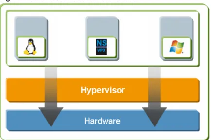
The following figure shows the bare-metal solution architecture of NetScaler® VPX™ on
XenServer.
Figure 1-1. NetScaler VPX on XenServer
The bare-metal solution architecture has the following components:
Hardware or physical layer:
Physical hardware components including memory, CPU, network cards, and disk drives.
Xen hypervisor:
Thin layer of software that runs on top of the hardware. The Xen hypervisor gives each virtual machine a dedicated view of the hardware.
Virtual machine:
Operating system hosted on the hypervisor and appearing to the user as a separate physical computer. However, the machine shares physical resources with other virtual machines, and it is portable because the virtual machine is abstracted from physical hardware.
A NetScaler VPX virtual machine, or virtual appliance, is installed on the Xen
appears to the users as an independent NetScaler appliance with its own network identity, user authorization and authentication capabilities, configuration, applications, and data. The paravirtualization technique enables the virtual machines and the hypervisor to work together to achieve high performance for I/O and for CPU and memory virtualization.
For more information about XenServer, see the XenServer documentation at http:// support.citrix.com/product/xens/.
XenCenter
XenCenter® is a graphical virtualization-management interface for XenServer®,
enabling you to manage servers, resource pools, and shared storage, and to deploy, manage, and monitor virtual machines from your Windows desktop machine. Use XenCenter to install NetScaler VPX on XenServer.
For more information about XenCenter, see the XenServer documentation at http:// support.citrix.com/product/xens/.
Command Center
Command Center is a management and monitoring solution for Citrix application networking products that include NetScaler, NetScaler VPX, Citrix Access Gateway™
Enterprise Edition, Citrix® Branch Repeater™, Branch Repeater VPX™, and Citrix
Repeater™. Command Center enables network administrators and operations teams to
manage, monitor, and troubleshoot the entire global application delivery infrastructure from a single, unified console.
This centralized management solution simplifies operations by providing administrators with enterprise-wide visibility and automating management tasks that need to be executed across multiple devices.
Command Center is available with Citrix NetScaler Enterprise and Platinum editions. You can use Command Center to provision NetScaler VPX on XenServer, and then you can manage and monitor the virtual appliances from Command Center.
Note: You must use the XenCenter client to manage XenServer. You cannot manage XenServer from Command Center.
For more information about Command Center, see the Command Center documentation at http://edocs.citrix.com.
NetScaler VPX Setup for the VMware ESX
Platform
The NetScaler® VPX™ setup for the VMware ESX platform requires a VMware ESX or ESXi
server and the vSphere client.
VMware ESX and ESXi are virtualization products based on bare-metal architecture, offered by VMware, Inc. Citrix NetScaler VPX can be hosted on a VMware ESX or ESXi server.
For more information about VMware ESX, see http://www.vmware.com/.
The vSphere client is a graphical interface for managing virtual machines on VMware ESX servers. You use the vSphere client to allocate resources on the ESX server to virtual appliances installed on the server or to deallocate resources. For example, you can allocate virtual network ports to a virtual appliance.
Chapter 2
Understanding the NetScaler
Topics:
• Switching Features
• Security and Protection Features
• Optimization Features
• Where Does a NetScaler Fit in the Network?
• How a NetScaler
Communicates with Clients and Servers
• Understanding Policies and Expressions
• Processing Order of Features
The Citrix® NetScaler® product is an application switch that
performs application-specific traffic analysis to intelligently distribute, optimize, and secure Layer 4-Layer 7 (L4-L7) network traffic for web applications. For example, a
NetScaler makes load balancing decisions on individual HTTP requests rather than on the basis of long-lived TCP
connections, so that the failure or slowdown of a server is managed much more quickly and with less disruption to clients. The NetScaler feature set can be broadly categorized as consisting of switching features, security and protection features, and server-farm optimization features.
Switching Features
When deployed in front of application servers, a NetScaler ensures optimal distribution of traffic by the way in which it directs client requests. Administrators can segment application traffic according to information in the body of an HTTP or TCP request, and on the basis of L4-L7 header information such as URL, application data type, or cookie. Numerous load balancing algorithms and extensive server health checks improve application availability by ensuring that client requests are directed to the appropriate servers.
Security and Protection Features
NetScaler security and protection features protect web applications from application-layer attacks. A NetScaler allows legitimate client requests and can block malicious requests. It provides built-in defenses against denial-of-service (DoS) attacks and supports features that protect applications against legitimate surges in application traffic that would otherwise overwhelm the servers. An available built-in firewall protects web applications from application-layer attacks, including buffer overflow exploits, SQL injection attempts, cross-site scripting attacks, and more. In addition, the firewall provides identity theft protection by securing confidential corporate information and sensitive customer data.
Optimization Features
Optimization features offload resource-intensive operations such as Secure Sockets Layer (SSL) processing, data compression, client keep-alive, TCP buffering, and the caching of static and dynamic content from servers. This improves the performance of the servers in the server farm and therefore speeds up applications. A NetScaler supports several transparent TCP optimizations, which mitigate problems caused by high latency and congested network links, accelerating the delivery of applications while requiring no configuration changes to clients or servers.
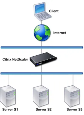
Where Does a NetScaler Fit in the Network?
A NetScaler resides between the clients and the servers, so that client requests and server responses pass through it. In a typical installation, virtual servers (vservers) configured on the NetScaler provide connection points that clients use to access the applications behind the NetScaler. In this case, the NetScaler owns public IP addresses that are associated with its vservers, while the real servers are isolated in a private network. It is also possible to operate the NetScaler in a transparent mode as an L2 bridge or L3 router, or even to combine aspects of these and other modes.
Physical Deployment Modes
A NetScaler logically residing between clients and servers can be deployed in either of two physical modes: inline and one-arm. In inline mode, multiple network interfaces are connected to different Ethernet segments, and the NetScaler is placed between the clients and the servers. The NetScaler has a separate network interface to each client network and a separate network interface to each server network. The NetScaler and the servers can exist on different subnets in this configuration. It is possible for the servers to be in a public network and the clients to directly access the servers through the NetScaler, with the NetScaler transparently applying the L4-L7 features. Usually, vservers (described later) are configured to provide an abstraction of the real servers. The following figure shows a typical inline deployment.
Figure 2-1. Inline Deployment
In one-arm mode, only one network interface of the NetScaler is connected to an Ethernet segment. The NetScaler in this case does not isolate the client and server sides of the network, but provides access to applications through configured vservers. One-arm mode can simplify network changes needed for NetScaler installation in some environments.
For examples of inline (two-arm) and one-arm deployment, see Understanding Common Network Topologies on page 49.
Citrix NetScaler as an L2 Device
A NetScaler functioning as an L2 device is said to operate in L2 mode. In L2 mode, the NetScaler forwards packets between network interfaces when all of the following conditions are met:
w The packets are destined to another device's media access control (MAC) address. w The destination MAC address is on a different network interface.
w The network interface is a member of the same virtual LAN (VLAN).
By default, all network interfaces are members of a pre-defined VLAN, VLAN 1. Address Resolution Protocol (ARP) requests and responses are forwarded to all network
interfaces that are members of the same VLAN. To avoid bridging loops, L2 mode must be disabled if another L2 device is working in parallel with the NetScaler.
For information about how the L2 and L3 modes interact, see Configuring Modes of Packet Forwarding on page 59.
For information about configuring L2 mode, see Enabling and Disabling Layer 2 Mode on page 60.
Citrix NetScaler as a Packet Forwarding Device
A NetScaler can function as a packet forwarding device, and this mode of operation is called L3 mode. With L3 mode enabled, the NetScaler forwards any received unicast packets that are destined for an IP address that it does not have internally configured, if there is a route to the destination. A NetScaler can also route packets between VLANs. In both modes of operation, L2 and L3, a NetScaler generally drops packets that are in: w Multicast frames
w Unknown protocol frames destined for a NetScaler's MAC address (non-IP and non-ARP) w Spanning Tree protocol (unless BridgeBPDUs is ON)
For information about how the L2 and L3 modes interact, see Configuring Modes of Packet Forwarding on page 59.
For information about configuring the L3 mode, see Enabling and Disabling Layer 3 Mode on page 62.
How a NetScaler Communicates with Clients
and Servers
A NetScaler is usually deployed in front of a server farm and functions as a transparent TCP proxy between clients and servers, without requiring any client-side configuration. This basic mode of operation is called Request Switching technology and is the core of NetScaler functionality. Request Switching enables a NetScaler to multiplex and offload
the TCP connections, maintain persistent connections, and manage traffic at the request (application layer) level. This is possible because the NetScaler can separate the HTTP request from the TCP connection on which the request is delivered.
Depending on the configuration, a NetScaler may process the traffic before forwarding the request to a server. For example, if the client attempts to access a secure
application on the server, the NetScaler might perform the necessary SSL processing before sending traffic to the server.
To facilitate efficient and secure access to server resources, a NetScaler uses a set of IP addresses collectively known as NetScaler-owned IP addresses. To manage your network traffic, you assign NetScaler-owned IP addresses to virtual entities that become the building blocks of your configuration. For example, to configure load balancing, you create virtual servers (vservers) to receive client requests and distribute them to services, which are entities representing the applications on your servers.
Understanding NetScaler-Owned IP Addresses
To function as a proxy, a NetScaler uses a variety of IP addresses. The key NetScaler-owned IP addresses are:
NetScaler IP address (NSIP)
The NSIP is the IP address for management and general system access to the NetScaler itself, and for HA communication.
Mapped IP address (MIP)
A MIP is used for server-side connections. It is not the IP address of the NetScaler. In most cases, when the NetScaler receives a packet, it replaces the source IP address with a MIP before sending the packet to the server. With the servers abstracted from the clients, the NetScaler manages connections more efficiently.
Virtual server IP address (VIP)
A VIP is the IP address associated with a vserver. It is the public IP address to which clients connect. A NetScaler managing a wide range of traffic may have many VIPs configured.
Subnet IP address (SNIP)
When the NetScaler is attached to multiple subnets, SNIPs can be configured for use as MIPs providing access to those subnets. SNIPs may be bound to specific VLANs and interfaces.
IP Set
An IP set is a set of IP addresses, which are configured on the NetScaler appliance as SNIPs or MIPs. An IP set is identified with a meaningful name that helps in identifying the usage of the IP addresses contained in it.
Net Profile
A net profile (or network profile) contains an IP address or an IP set. A net profile can be bound to load balancing or content switching virtual servers, services, service groups, or monitors. During communication with physical servers or peers, the
NetScaler appliance uses the addresses specified in the profile as the source IP address. Citrix NetScaler VPX Getting Started Guide
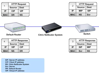
How Traffic Flows Are Managed
Because a NetScaler functions as a TCP proxy, it translates IP addresses before sending packets to a server. When you configure a vserver, clients connect to a VIP on the NetScaler instead of directly connecting to a server. Based on the settings on the vserver, the NetScaler selects an appropriate server and sends the client's request to that server. By default, the NetScaler uses a MIP or SNIP to establish connections with the server, as shown in the following figure.
Figure 2-2. Vserver-Based Connections
Note: You can use SNIP instead of MIP in the preceding figure.
In the absence of a vserver, when a NetScaler receives a request, it transparently forwards the request to the server. This is called the transparent mode of operation. When operating in transparent mode, a NetScaler translates the source IP addresses of incoming client requests to the MIP or SNIP but does not change the destination IP address. For this mode to work, L2 or L3 mode needs to be configured appropriately. For cases in which the servers need the actual client IP address, the NetScaler can be configured to modify the HTTP header by inserting the client IP address as an
additional field, or configured to use the client IP address instead of the MIP or SNIP for connections to the servers.
Traffic Management Building Blocks
The configuration of a NetScaler is typically built up with a series of virtual entities that serve as building blocks for traffic management. The building block approach helps separate traffic flows. Virtual entities are abstractions, typically representing IP addresses, ports, and protocol handlers for processing traffic. Clients access applications and resources through these virtual entities. The most commonly used entities are vservers and services. Vservers represent groups of servers in a server farm or remote network, and services represent specific applications on each server.
Most features and traffic settings are enabled through virtual entities. For example, you can configure a NetScaler to compress all server responses to a client that is connected to the server farm through a particular vserver. To configure the NetScaler for a particular environment, you need to identify the appropriate features and then choose the right mix of virtual entities to deliver them. Most features are delivered through a cascade of virtual entities that are bound to each other. In this case, the virtual entities are like blocks being assembled into the final structure of a delivered application. You can add, remove, modify, bind, enable, and disable the virtual entities to configure the features. The following figure shows the concepts covered in this section.
Figure 2-3. How Traffic Management Building Blocks Work
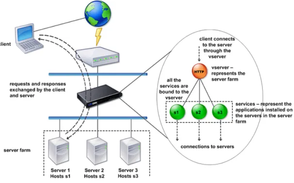
A Simple Load Balancing Configuration
In the example shown in the following figure, the NetScaler is configured to function as a load balancer. For this configuration, you need to configure virtual entities specific to Citrix NetScaler VPX Getting Started Guide
distributes client requests across several servers and thus optimizes the utilization of resources.
The basic building blocks of a typical load balancing configuration are services and load balancing vservers. The services represent the applications on the servers. The vservers abstract the servers by providing a single IP address to which the clients connect. To ensure that client requests are sent to a server, you need to bind each service to a vserver. That is, you must create services for every server and bind the services to a vserver. Clients use the VIP to connect to a NetScaler. When the NetScaler receives client requests on the VIP, it sends them to a server determined by the load balancing algorithm. Load balancing uses a virtual entity called a monitor to track whether a specific configured service (server plus application) is available to receive requests.
Figure 2-4. Load Balancing Virtual Server, Services, and Monitors
In addition to configuring the load balancing algorithm, you can configure several parameters that affect the behavior and performance of the load balancing configuration. For example, you can configure the vserver to maintain persistence based on source IP address. The NetScaler then directs all requests from any specific IP address to the same server.
Understanding Virtual Servers
A vserver is a named NetScaler entity that external clients can use to access
applications hosted on the servers. It is represented by an alphanumeric name, virtual IP address (VIP), port, and protocol. The name of the vserver is only of local
attempts to access applications on a server, it sends a request to the VIP instead of the IP address of the physical server. When the NetScaler receives a request on the VIP, it terminates the connection at the vserver and uses its own connection with the server on behalf of the client. The port and protocol settings of the vserver determine the applications that the vserver represents. For example, a web server can be represented by a vserver and a service whose port and protocol are set to 80 and HTTP,
respectively. Multiple vservers can use the same VIP but different protocols and ports. Vservers are points for delivering features. Most features, like compression, caching, and SSL offload, are normally enabled on a vserver. When the NetScaler receives a request on a VIP, it chooses the appropriate vserver by the port on which the request was received and its protocol. The NetScaler then processes the request as appropriate for the features configured on the vserver.
In most cases, vservers work in tandem with services. You can bind multiple services to a vserver. These services represent the applications running on physical servers in a server farm. After the NetScaler processes requests received on a VIP, it forwards them to the servers as determined by the load balancing algorithm configured on the vserver. The following figure shows these concepts.
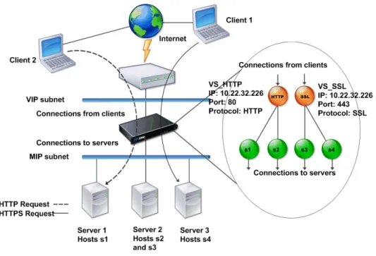
Figure 2-5. Multiple Virtual Servers on a Single VIP
The preceding figure shows a configuration consisting of two vservers with a common VIP but different ports and protocols. Each of these vservers has two services bound to it. The services s1 and s2 are bound to VS_HTTP and represent the HTTP applications on Server 1 and Server 2. The services s3 and s4 are bound to VS_SSL and represent the
applications). When the NetScaler receives an HTTP request on the VIP, it processes the request based on the settings of VS_HTTP and sends it to either Server 1 or Server 2. Similarly, when the NetScaler receives an HTTPS request on the VIP, it processes it based on the settings of VS_SSL and it sends it to either Server 2 or Server 3.
Vservers are not always represented by specific IP address, port numbers, or protocols. They can be represented by wildcards, in which case they are known as wildcard vservers. For example, when you configure a vserver with a wildcard instead of a VIP, but with a specific port number, the NetScaler intercepts and processes all traffic conforming to that protocol and destined for the predefined port. For vservers with wildcards instead of VIPs and port numbers, the NetScaler intercepts and processes all traffic conforming to the protocol.
Vservers can be grouped into the following categories:
Load balancing virtual server
Receives and redirects requests to an appropriate server. Choice of the appropriate server is based on which of the various load balancing methods the user configures.
Cache redirection virtual server
Redirects client requests for dynamic content to origin servers and static content to cache servers. Cache redirection vservers often work in conjunction with load balancing vservers.
Content switching virtual server
Directs traffic to a server on the basis of the content that the client has requested. For example, you can create a content switching vserver that directs all client requests for images to a server that serves images only. Content switching vservers often work in conjunction with load balancing vservers.
Virtual private network (VPN) virtual server
Decrypts tunneled traffic and sends it to intranet applications.
SSL virtual server
Receives and decrypts SSL traffic, and then redirects to an appropriate server. Choosing the appropriate server is similar to choosing a load balancing virtual server.
Understanding Services
Services represent applications on a server. While services are normally combined with vservers, in the absence of a vserver, a service can still manage application-specific traffic. For example, you can create an HTTP service on a NetScaler to represent a web server application. When the client attempts to access a web site hosted on the web server, the NetScaler intercepts the HTTP requests and creates a transparent
connection with the web server.
In service-only mode, a NetScaler functions as a proxy. It terminates client
connections, uses a SNIP or MIP to establish a connection to the server, and translates incoming client requests to the SNIP or MIP. Although the clients send requests directly to the IP address of the server, the server sees them as coming from the SNIP or MIP. The NetScaler translates the IP addresses, port numbers, and sequence numbers.
A service is also a point for applying features. Consider the example of SSL acceleration. To use this feature, you must create an SSL service and bind an SSL certificate to the service. When the NetScaler receives an HTTPS request, it decrypts the traffic and sends it, in clear text, to the server. Only a limited set of features can be configured in the service-only case.
Services use entities called monitors to track the health of applications. Every service has a default monitor, which is based on the service type, bound to it. As specified by the settings configured on the monitor, the NetScaler sends probes to the application at regular intervals to determine its state. If the probes fail, the NetScaler marks the service as down. In such cases, the NetScaler responds to client requests with an appropriate error message or re-routes the request as determined by the configured load balancing policies.
Understanding Policies and Expressions
A policy defines specific details of traffic filtering and management on a NetScaler. It consists of two parts: the expression and the action. The expression defines the types of requests that the policy matches. The action tells the NetScaler what to do when a request matches the expression. As an example, the expression might be to match a specific URL pattern to a type of security attack, with the action being to drop or reset the connection. Each policy has a priority, and the priorities determine the order in which the policies are evaluated.
When a NetScaler receives traffic, the appropriate policy list determines how to process the traffic. Each policy on the list contains one or more expressions, which together define the criteria that a connection must meet to match the policy. For all policy types except Rewrite policies, a NetScaler implements only the first policy that a request matches, not any additional policies that it might also match. For Rewrite policies, the NetScaler evaluates the policies in order and, in the case of multiple matches, performs the associated actions in that order. Policy priority is important for getting the results you want.
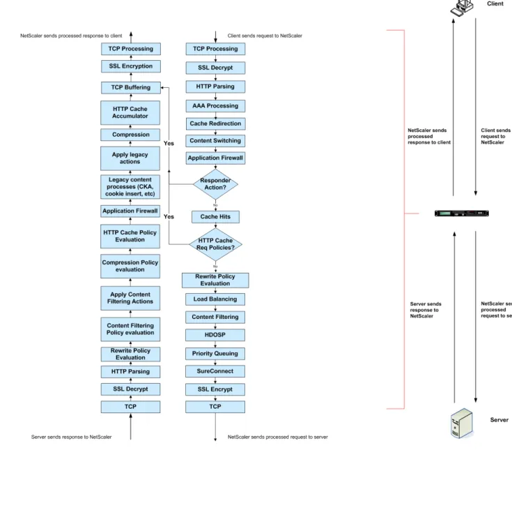
Processing Order of Features
Depending on requirements, you can choose to configure multiple features. For example, you might choose to configure both compression and SSL offload. As a result, an outgoing packet might be compressed and then encrypted before being sent to the client.
The following figure shows the L7 packet flow in the NetScaler.
Chapter 3
Installing NetScaler Virtual Appliances on
XenServer
Topics:
• Prerequisites for Installing NetScaler Virtual Appliances on XenServer
• Installing NetScaler Virtual Appliances on XenServer by Using XenCenter
To install Citrix® NetScaler® virtual appliances on Citrix®
XenServer®, you must first install XenServer on a machine
with adequate system resources. To perform the NetScaler VPX installation, you use Citrix® XenCenter®, which must be
installed on a remote machine that can connect to the XenServer host through the network.
Note: After the initial configuration of the NetScaler
appliance, if you want to upgrade the appliance to the latest software release, see the Citrix NetScaler Migration Guide at
Prerequisites for Installing NetScaler Virtual
Appliances on XenServer
Before you begin installing a virtual appliance, do the following:
w Install XenServer® version 5.6 or later on hardware that meets the minimum
requirements.
w Install XenCenter® on a management workstation that meets the minimum system
requirements.
w Obtain VPX license files. For more information about VPX licenses, see the NetScaler
VPX Licensing Guide at http://support.citrix.com/article/ctx122426.
XenServer Hardware Requirements
The following table describes the minimum hardware requirements for a XenServer platform running NetScaler nCore VPX.
Table 3-1. Minimum System Requirements for XenServer Running NetScaler nCore VPX
Component Requirement
CPU 2 or more 64-bit x86 CPUs with virtualization
assist (Intel-VT or AMD-V) enabled
Note: To run NetScaler VPX, hardware support for virtualization must be enabled on the XenServer host. Make sure that the BIOS option for virtualization support is not
disabled. Consult your BIOS documentation for more details.
RAM 3 gigabytes (GB)
Disk space Locally attached storage (PATA, SATA, SCSI) with 40 GB of disk space
Note: XenServer installation creates a 4 GB partition for the XenServer host control domain; the remaining space is available for NetScaler VPX and other virtual machines.
Component Requirement
Network Interface Card (NIC) 1 one gigabits per second (Gbps) NIC; 2 one Gbps NICs recommended
For information about installing XenServer, see the XenServer documentation at http:// support.citrix.com/product/xens/.
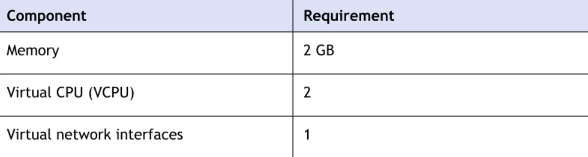
The following table lists the virtual computing resources that XenServer must provide for each NetScaler nCore VPX.
Table 3-2. Minimum Virtual Computing Resources Required for Running NetScaler nCore VPX
Component Requirement
Memory 2 GB
Virtual CPU (VCPU) 2
Virtual network interfaces 1
Note: For production use of NetScaler VPX, it is recommended that CPU priority (in virtual machine properties) be set to the highest level in order to improve scheduling behavior and network latency.
XenCenter System Requirements
XenCenter® is a Windows client application. It cannot run on the same machine as the
XenServer® host. The following table describes the minimum system requirements.
Table 3-3. Minimum System Requirements for XenCenter Installation
Component Requirement
Operating system Windows XP, Windows Server 2003, or Windows Vista
.NET framework Version 2.0 or later
CPU 750 megahertz (MHz)
Recommended: 1 gigahertz (GHz) or faster
Component Requirement
RAM 1 GB
Recommended: 2 GB
Network Interface Card (NIC) 100 megabits per second (Mbps) or faster NIC
For information about installing XenCenter, see the XenServer documentation at http:// support.citrix.com/product/xens/.
Installing NetScaler Virtual Appliances on
XenServer by Using XenCenter
After you have installed and configured XenServer and XenCenter, you can use
XenCenter to install virtual appliances on XenServer. The number of virtual appliances that you can install depends on the amount of memory available on the hardware that is running XenServer.
After you have used XenCenter to install the initial NetScaler virtual appliance (.xva image) on XenServer, you have the option to use Command Center to provision
NetScaler VPX. For more information, see the Command Center documentation at http:// edocs.citrix.com/.
To install NetScaler virtual appliances on XenServer by using XenCenter
1. Start XenCenter on your workstation. 2. On the Server menu, click Add.
3. In the Add New Server dialog box, in the Hostname text box, type the IP address or DNS name of the XenServer that you want to connect to.
4. In the User Name and Password text boxes, type the administrator credentials, and then click Connect.
The XenServer name appears in the navigation pane with a green circle, which indicates that the XenServer is connected.
5. In the navigation pane, click the name of the XenServer on which you want to install NetScaler VPX.
6. On the VM menu, click Import.
7. In the Import dialog box, in Import file name, browse to the location at which you saved the NetScaler VPX .xva image file. Make sure that the Exported VM option is selected, and then click Next.
8. Select the XenServer on which you want to install the virtual appliance, and then click Next.
9. Select the local storage repository in which to store the virtual appliance, and then click Import to begin the import process.
10. You can add, modify, or delete virtual network interfaces as required. When finished, click Next.
11. Click Finish to complete the import process.
Note: To view the status of the import process, click the Log tab.
12. If you want to install another virtual appliance, repeat steps 5 through 11.
Chapter 4
Installing NetScaler Virtual Appliances on
VMware ESX
Topics:
• Prerequisites for Installing NetScaler Virtual Appliances on VMware
• Installing NetScaler Virtual Appliances on VMware ESX 4.0
• Installing NetScaler Virtual Appliances on VMware ESX 3.5
Before installing Citrix® NetScaler® virtual appliances on
VMware ESX, make sure that VMware ESX server is installed on a machine with adequate system resources. To install virtual appliances on VMware ESX version 4.0, you use VMware vSphere client. On VMware ESX version 3.5, you use the VMware Open Virtualization Format (OVF) tool. The client or tool must be installed on a remote machine that can connect to VMware ESX through the network.
After the installation, you can use vSphere client 4.0 to manage virtual appliances on VMware ESX 4.0, or you can use VMware Infrastructure (VI) client 2.5 to manage virtual appliances on VMware ESX 3.5.
Note:
The VMware vSphere client shows the guest operating system as "Sun Solaris 10" for NetScaler VPX. This is by design because VMware ESX 3.5 does not recognize FreeBSD. After the initial configuration of the NetScaler appliance, if you want to upgrade the appliance to the latest software release, see the Citrix NetScaler Migration Guide at http:// support.citrix.com/article/ctx123856.
Prerequisites for Installing NetScaler Virtual
Appliances on VMware
Before you begin installing a virtual appliance, do the following:
w Install VMware ESX version 3.5 or later on hardware that meets the minimum requirements.
w Install VMware Client on a management workstation that meets the minimum system requirements.
w Install VMware OVF Tool (required for VMware ESX version 3.5) on a management workstation that meets the minimum system requirements.
w Download the NetScaler VPX setup files.
w Label the physical network ports of VMware ESX.
w Obtain NetScaler VPX license files. For more information about NetScaler VPX licenses, see the NetScaler VPX Licensing Guide at http://support.citrix.com/article/ ctx122426.
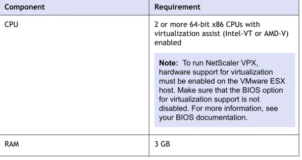
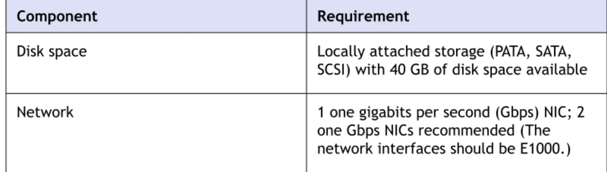
VMware ESX Hardware Requirements
The following table describes the minimum system requirements for VMware EXS servers running NetScaler nCore VPX.
Table 4-1. Minimum System Requirements for VMware ESX Servers Running NetScaler nCore VPX
Component Requirement
CPU 2 or more 64-bit x86 CPUs with
virtualization assist (Intel-VT or AMD-V) enabled
Note: To run NetScaler VPX, hardware support for virtualization must be enabled on the VMware ESX host. Make sure that the BIOS option for virtualization support is not disabled. For more information, see your BIOS documentation.
Component Requirement
Disk space Locally attached storage (PATA, SATA,
SCSI) with 40 GB of disk space available
Network 1 one gigabits per second (Gbps) NIC; 2
one Gbps NICs recommended (The network interfaces should be E1000.) For information about installing VMware ESX, see http://www.vmware.com/. The following table lists the virtual computing resources that the VMware ESX server must provide for each NetScaler nCore VPX.
Table 4-2. Minimum Virtual Computing Resources Required for Running NetScaler nCore VPX
Component Requirement
Memory 2 GB
Virtual CPU (VCPU) 2
Virtual network interfaces 1
Note: If the virtual appliance is installed on ESX 3.5 or ESXi 3.5, you can install a maximum of 4 virtual network interfaces. If the virtual appliance is installed on ESX 4.0, the maximum is 10.
Disk space 20 GB
Note: This is in addition to any disk requirements for the hypervisor.
Note: For production use of NetScaler VPX, the full memory allocation must be reserved. CPU MHz should also be reserved at least equal to the MHz of one CPU core in the system.
VMware vSphere Client 4.0 System Requirements
VMware vSphere is a client application that can run on Windows and Linux operating systems. It cannot run on the same machine as the VMware ESX server. The following table describes the minimum system requirements.Table 4-3. Minimum System Requirements for VMware vSphere Client Installation
Component Requirement
Operating system For detailed requirements from VMware, search for the "vSphere Compatibility Matrixes" PDF file at http://
kb.vmware.com/.
CPU 750 megahertz (MHz); 1 gigahertz (GHz)
or faster recommended
RAM 1 GB; 2 GB recommended
Network Interface Card (NIC) 100 Mbps or faster NIC
For information about installing vSphere client 4.0, see http://www.vmware.com/.
Note: When you connect the vSphere client 4.0 to ESX 3.5, the vSphere client downgrades to VMware Infrastructure (VI) client version 2.5, which is the only version that is compatible with ESX 3.5.
OVF Tool 1.0 System Requirements
OVF Tool is a client application that can run on Windows and Linux systems. It cannot run on the same machine as the VMware ESX server. You need to use VMware OVF Tool version 1.0 for installing virtual appliances on ESX 3.5. The following table describes the minimum system requirements.
Table 4-4. Minimum System Requirements for OVF Tool Installation
Component Requirement
Operating system For detailed requirements from VMware, search for the "OVF Tool User Guide" PDF file at http://kb.vmware.com/.
CPU 750 MHz minimum, 1 GHz or faster
Component Requirement
RAM 1 GB Minimum, 2 GB recommended.
Network Interface Card (NIC) 100 Mbps or faster NIC
For information about installing OVF, search for the "OVF Tool User Guide" PDF file at http://kb.vmware.com/.
Downloading the NetScaler VPX Setup Files
The NetScaler VPX setup package for VMWare ESX follows the Open Virtual Machine (OVF) format standard. You can download the files from MyCitrix.com. You will need a My Citrix account to log on. If you do not have a My Citrix account, access the home page at http://www.mycitrix.com, click the New Users link, and follow the
instructions to create a new My Citrix account.
Once logged in, navigate the following path from the My Citrix home page: MyCitrix.com > Downloads > NetScaler > Virtual Appliances.
Copy the following files to a workstation on the same network as the ESX server. Copy all three files into the same folder.
w ESX-<release number>-<build number>-disk1.vmdk (for example, NSVPX-ESX--39.8-disk1.vmdk)
w NSVPX-ESX-<release number>-<build number>.ovf (for example, NSVPX-ESX--39.8.ovf) w NSVPX-ESX-<release number>-<build number>.mf (for example, NSVPX-ESX--39.8.mf )
Labeling the Physical Network Ports of VMware ESX
Before installing a NetScaler virtual appliance, you need to label at least one physical network port of VMware ESX in a particular format. The labeling format is NS_NIC_1_1, NS_NIC_1_2, and so on. These ports will be used by the virtual appliances that you install. An interface can be used by more than one virtual appliance.
To label the physical network ports of VMware ESX server
1. Log on to the VMware ESX server by using the vSphere client.
2. On the vSphere client, select the Configuration tab, and then click Networking. 3. At the top-right corner, click Add Networking, to start the Add Network Wizard. 4. In Connection Type, select Virtual Machine, and then click Next.
5. Scroll through the list of vSwitch physical adapters, and choose the physical port that will map to interface 1/1 on the virtual appliances.
6. Enter NS_NIC_1_1 as the name of the vSwitch that will be associated with interface 1/1 of the virtual appliances.
7. Click Next to finish the vSwitch creation. Repeat the procedure, beginning with step 2, to add any additional interfaces to be used by your virtual appliances. Label the interfaces sequentially, in the correct format (for example, NS_NIC_1_2).
Installing NetScaler Virtual Appliances on
VMware ESX 4.0
After you have installed and configured VMware ESX 4.0, you can use VMware vSphere client to install virtual appliances on the VMware ESX. The number of virtual appliances that you can install depends on the amount of memory available on the hardware that is running VMware ESX.
To install NetScaler virtual appliances on VMware
ESX 4.0 by using VMware vSphere Client
1. Start the VMware vSphere client on your workstation.
2. In the IP address / Name text box, type the IP address of the VMware ESX server that you want to connect to.
3. In the User Name and Password text boxes, type the administrator credentials, and then click Login.
4. On the File menu, click Deploy OVF Template.
5. In the Deploy OVF Template dialog box, in Deploy from file, browse to the location at which you saved the NetScaler VPX setup files, select the .ovf file, and click Next.
6. Map the networks shown in the VPX OVF template to the networks that you
configured on the ESX host. Click Next to start installing VPX on VMware ESX. When installation is complete, a pop-up window informs you of the successful installation. 7. You are now ready to start the NetScaler VPX. In the navigation pane, select the
NetScaler VPX that you have just installed and, from the right-click menu, select
Power On. Click the Console tab to emulate a console port.
8. If you want to install another virtual appliance, repeat steps 4 through 6.
Installing NetScaler Virtual Appliances on
VMware ESX 3.5
To install virtual appliances on ESX 3.5, you need to use the VMware OVF tool, version 1.0. The number of virtual appliances that you can install depends on the amount of memory available on the hardware that is running VMware ESX. After installation, you
can use the VMware Infrastructure (VI) client 2.5 to manage the virtual appliances on VMware ESX version 3.5.
Note: You cannot use version 4.0 of the vSphere client for installing virtual appliances on ESX 3.5. If you connect the vSphere 4.0 client to ESX 3.5, the vSphere client downgrades to VI client version 2.5, which supports only the OVF 0.9 standard. The NetScaler VPX installation package is based on the OVF 1.0.
To install NetScaler virtual appliances on VMware
ESX 3.5 by using the VMware OVF Tool
1. On your workstation, open the command-line interface and execute the following command:
ovftool <path of the NetScaler VPX OVF file> vi:// <Username>:<Password>@<IP address of the ESX server>
For example, in Windows command shell, type:
ovftool c:/NetScalerVPX vi://root:free@<10.217.20.14>
2. When the OVF tool has installed the virtual appliances on the ESX server, use the VI client to log on to the VMware ESX server on which you performed the installation. 3. In the navigation pane, right-click a virtual appliance that you want to enable, and
then click Power On. Repeat this for each virtual appliance you want to enable. 4. Click the Console tab to emulate a console port.
Chapter 5
Configuring the Basic System Settings
Topics:
• Setting Up the Initial Configuration by Using the NetScaler VPX Console
• Configuring NetScaler VPX by Using the Command-Line Interface
• Configuring NetScaler VPX by Using the Configuration Utility
After installing a Citrix® NetScaler® VPX virtual appliance, you
need to access it to configure the basic settings. Initially, you must access the NetScaler command line through the
respective management application of the virtualization host (either Citrix XenCenter for Citrix XenServer or VMware vSphere client for VMware ESX) to specify a NetScaler IP (NSIP) address, subnet mask, and default gateway. The NSIP is the management address at which you can then access the NetScaler command line, through an SSH client, or access the configuration utility. You can use either of these access methods, or the console, to continue with basic configuration. To access the configuration utility, type the NSIP into the address field of any browser (for example, http:// <NSIP_address>). You need Java RunTime Environment (JRE) version 1.6 or later.
Setting Up the Initial Configuration by Using the
NetScaler VPX Console
Your first task after installing a NetScaler virtual appliance on a virtualization host is to use the NetScaler VPX console in the XenCenter client or vSphere client to configure the following initial settings.
Note: If you have installed a virtual appliance on XenServer by using Command Center, you do not have to configure these settings. Command Center implicitly configures the settings during installation. For more information about provisioning VPX from Command Center, see the Command Center documentation at http:// edocs.citrix.com.
NetScaler IP address (NSIP):
The IP address at which you access a NetScaler or a NetScaler virtual appliance for management purposes. A physical NetScaler or virtual appliance can have only one NSIP. You must specify this IP address when you configure the virtual appliance for the first time. You cannot remove an NSIP address.
Netmask:
The subnet mask associated with the NSIP address.
Default Gateway:
You must add a default gateway on the virtual appliance if you want access it through SSH or the configuration utility from an administrative workstation or laptop that is on a different network.
To configure the initial settings on the virtual
appliance through the VPX Console by using the
management application
1. Connect to the XenServer or VMware ESX server on which the virtual appliance is installed by using XenCenter or vSphere client, respectively.
2. In the details pane, on the Console tab, log on to the virtual appliance by using the administrator credentials.
3. At the prompts, enter the NSIP address, subnet mask, and default gateway, and then save the configuration.
After you have set up an initial configuration through the NetScaler VPX Console in the management application, you can use either the NetScaler command-line interface or the configuration utility to complete the configuration or to change the initial settings.