
1
__________________________________________________________________________________
Comparison of
Underground and Overhead
Transmission Options in Iceland
(132 and 220kV)
__________________________________________________________________________________
Prepared by
November, 2013
THIS IS AN INDEPENDENT REPORT BY METSCO ENERGY
SOLUTIONS INC. (MES) AN ENGINEERING CONSULTING
CORPORATION IN CANADA. MES FOCUSES ON ENGINEERING
ANALYSIS AND ASSET MANAGEMENT SERVICES FOR THE
ELECTRICAL POWER INDUSTRY. THIS REPORT WAS
COMMISSIONED BY LANDVERND IN ICELAND. ALL
2
Executive Summary
This report provides a general comparison of the overhead and underground options currently under discussion in Iceland regarding rebuild and strengthening of the current 132 kV/220 kV transmission system.
Although Overhead Lines are still the dominant transmission construction around the world in terms of footprint the innovation of Underground Cable and accessories technology has made underground transmission projects more and more feasible in the last few decades. In Iceland this is also the case, since 1990 Underground Cables have increasingly been constructed on distribution voltages as well as on transmission voltages up to and including 132 kV and although specific numbers are not available the experience has been good in terms of reliability and operability.
The main benefits of Underground Cables include being more aesthetical in surroundings, less losses, less operating costs and being non-susceptible to storms, salt contamination and icing. The main benefits of Overhead Lines on the other hand are that they are cheaper and easier to construct, easier to fix when failed and more flexible in terms of maximum load capacity.
True comparison of costs can only be performed by taking into consideration both construction and operating costs or so called life-cycle costs. With the estimated lifetime of both Underground Cables and Overhead Lines at 60 years full life cycle costs which include construction and operation costs is generally expected to be as shown in the table below for a typical 120 km line:
Total Costs Overhead M€ Underground M€ Overall Ratio (UG/OH) 132 kV 67.6 70.3 1.04 220 kV 96.8 116.0 1.20
Lifetime of modern Underground Cables is expected to be at least 60 years where care is taken in not overloading them similarly as has to be done with many other transmission assets such as power transformers. Overhead Lines do not have this limitation but they are directly susceptible to storms and icing loads which in worst cases may require major premature rebuild.
Another aspect which may be considered is that if Overhead Lines are nonetheless built in controversial scenic areas it is quite likely that they will be forced underground much before their 60 year lifetime is reached resulting in non-optimal investment.
When deciding whether to build overhead or underground not only the actual costs of the options need to be considered but also the benefits to customers and overall economy. It is important to strike a balance in stakeholders’ interests and recognizing the impact on businesses and economy as a whole. As costs can largely vary with specific aspects of projects a true comparison of costs should be done on individual cases but this general comparison does show that both the options are feasible and need to be seriously considered.
3
Samantekt skýrslu
Í þessari skýrslu er gerður almennur samanburður á loftlínum og jarðstrengjum í tengslum við umræðu á Íslandi um þessar mundir vegna áætlana um uppbyggingu á flutningskerfi raforku.
Enda þótt loftlínur séu enn ríkjandi í byggingu flutningskerfa í heiminum þegar á heildina er litið, hafa tækninýjungar og lækkandi verðlag í framleiðslu jarðstrengja og búnaði þeim tengdum gert notkun jarðstrengja í flutningskerfum sífellt vænlegri kost á síðustu áratugum. Þetta gildir einnig um Ísland, þar sem lagning jarðstrengja hefur aukist síðan um 1990 bæði í dreifi- og flutningskerfi allt að 132 kV spennu. Þó nákvæmar tölur liggi ekki fyrir hefur reynsla af jarðstrengjum almennt verið góð með tilliti til reksturs og áreiðanleika.
Það sem helst mælir með notkun jarðstrengja er fagurfræði- og umhverfislegt gildi, minni orkutöp, lægri rekstrarkostnaður og engin áhrif veðurs, seltu og ísingar. Hinsvegar eru loftlínur ódýrari í byggingu, auðveldari að gera við og veita meira svigrúm til aukningar á flutningsgetu.
Einungis er hægt að gera raunverulegan samanburð á kostnaði þessara valkosta með því að taka tillit til bæði stofn- og rekstrarkostnaðar eða svokallaðs líftímakostnaðar (e. life-cycle costs). Miðað við 60 ára líftíma bæði loftlína og jarðstrengja má almennt búast við að heildarkostnaður fyrir dæmigerða 120 km línulengd í dreifbýli sé eins og eftirfarandi tafla sýnir:
Heildarkostnaður Loftlínur (LL) M€ Jarðstrengir (JS) M€ Hlutfall (JS/LL) 132 kV 67.6 70.3 1.04 220 kV 96.8 116.0 1.20
Gert er ráð fyrir að nútíma jarðstrengir endist í að minnsta kosti 60 ár sé þess gætt að þeir séu reknir innan hitaþolmarka sem þeir eru hannaðir fyrir, líkt og ávallt þarf að hafa í huga með aflspenna og annan rafbúnað í flutningskerfum. Þessi hætta á yfirlestun á ekki við um loftlínur. Á hinn bóginn leiðir óveður og ísing í verstu tilfellum til ótímabærrar endurbyggingar stórra loftlínukafla.
Annað sem hafa ber í huga er að séu loftlínur byggðar á umdeildum svæðum, svo sem þar sem náttúruverndarsjónarmið eiga við, er ekki ólíklegt að þær línur verði rifnar og settar í jörð áður en 60 ára líftíma þeirra yrði náð, sem aftur myndi leiða til þess að fjárfestingin væri óhagkvæm.
Við ákvörðun um hvort leggja skuli jarðstreng eða loftlínu nægir ekki að bera saman líftímakostnað, heldur þarf að skoða heildarmyndina. Vega þarf og meta hagsmuni allra hagsmunaaðila og áhrifin á náttúru og umhverfi, fyrirtækin í landinu og þjóðarbúið í heild.
Rík áhersla er lögð á að ávallt þarf að skoða hvert verkefni fyrir sig, þar sem kostnaður bæði loftlína og jarðstrengja er breytilegur og fer eftir aðstæðum hverju sinni. Niðurstaða þess almenna samanburðar sem hér hefur verið gerður er hinsvegar sú að báðir valkostir eru raunhæfir og ekki verður hjá því komist að taka þá til raunverulegrar skoðunar þegar ákvörðun er tekin um einstök verkefni í flutningskerfinu.
4
Contents
Executive Summary ... 2
Samantekt skýrslu ... 3
Introduction ... 5
Electrical System and Infrastructure – Iceland ... 6
Overview - European Electricity Lines... 9
Overhead versus Underground Lines ... 11
Life Cycle Cost Comparison ... 15
Reliability and Availability of Power ... 18
Other Considerations ... 19
Safety ... 19
Right of Way ... 20
EMF ... 20
Environment ... 20
Tourism and local economy ... 21
Regulatory ... 22
Conclusion and Recommendations ... 23
5
Introduction
As economic growth in the world drives intensive electric energy demand, the need for advanced electric networks is fundamental for sustained and optimal usage of assets and resources available. For more than century electricity networks have primarily remained with the traditional model of being generated from generation plants, usually situated far from densely populated areas, transmitted through overhead transmission lines over long distances until they reach the locality where they are stepped down for commercial and residential use. Although the operational model of the system hasn’t completely changed, the advent of new technologies and smart grid concepts are bringing about some changes to the electricity generation, transmission and distribution systems around the world. One of these changes is increased installation of underground transmission networks as underground cables have become more advanced, reliable and cost effectivei.
The objective of this report is to provide an impartial analysis of the technical and business merits of building an Overhead Transmission line (OHTL) versus an Underground Transmission line (UGTL). Independent primary and secondary research of information available in the public domain in the form of data, reports, and links from around the world have been referenced and personal experience and interpretive analysis provided to construct the overall assessment. Consequently, this report will provide some constructive opinions to the various stakeholders in Iceland about their ongoing discussion regarding the feasibility of rebuilding an existing 132 kV OHTL with an OHTL at 220 kV level or with an UGTL at 132 kV level or 220 kV level.
The first underground transmission line was a 132 kV line constructed in 1927ii. The cable was fluid-filled and paper insulated. The fluid was necessary to dissipate the heat. For decades, reliability problems continued to be associated with constructing longer cables at higher voltages. The most significant issue was maintenance difficulties. Not until the mid-1960s did the technology advance sufficiently so that a high-voltage 345 kV line could be constructed underground. The lines though were still fluid filled. This caused significant maintenance, contamination, and infrastructure issues. Extruded cable systems (XLPE) have a major part to play in this new, competitive environment, especially when it comes to replacing overhead lines with underground cables. XLPE cable systems costs have decreased during the last decade and are likely to fall even further. At the same time, XLPE cable performance has increased enormously as cables today are water resistant and are expected to have longer lifetime than most other electrical system assets. This means that XLPE cable systems are able to compete with overhead lines, technically, environmentally and commercially. In the 1990s the first solid cable transmission line was constructed more than one mile in length and greater than 230 kViiiand now transmission cables are constructed on regular basis throughout the world and at greater lengths than ever before.
OHTL is still the dominant transmission construction around the world in terms of footprint. Innovation of underground cable and accessories technology have resulted in increased underground transmission networks projects in the last few decades. Other factors such as extreme weather have caused major power disruptions by damaging overhead structures to an irreparable state. As people and communities recover from lengthy outages, utility companies, politicians and social groups start questioning the
6
design philosophy and returns of investments of electric system infrastructure. Frank Alonso and Carolyn Greenwell, engineers at Science Applications International Corporation (SAIC) write in the aftermath of hurricane Sandy in the United States, “Although overhead power lines are typically more economical, they are susceptible to damage from wind-borne tree branches, debris and high wind and ice-loading conditions from extreme weather. The damages can cause extended power outages that in extreme cases cannot be restored for days or even weeks, as we have seen after Hurricane Sandy. The cost for repairing the physical damages can be in the billions of dollars. During long outages after a catastrophe, there are also associated intangible impacts to a utility's customers such as despair, discomfort, anxiety and helplessness
.”
iv In Iceland similar extreme events happen also regularly such as in 1991, 1995 and 2012. The event in 1991 resulted in over 550 distribution poles being destroyed with severe outages for customers whereas the event in 2012 had over 100 distribution poles destroyed and according to RARIK (Iceland State Electricity) that event would have been much more catastrophic if not for approximately half of their distribution lines having been replaced with underground cable in the last 20 years. The event of 2012 also caused damage to Landsnet’s transmission lines – specifically the 66kV transmission line from Laxá to Kópaskerv as well as the 132kV ring between Akureyri and Krafla.Other considerations also loom as construction needs, ongoing operating and maintenance activities, aesthetics and impact of natural habitat differ significantly between the overhead and underground systems.
Electrical System and Infrastructure – Iceland
Some key facts about the Electrical System and Infrastructure relevant to this report are provided below. The information is based on the National Energy Authority 2011 Report: vi
The Icelandic electricity system is an isolated system without any connection to other countries. There were 314,000 residents in December of 2010, living mostly along the coastline of 103 thousand square kilometers of land. Per capita electricity consumption is however among the highest levels in Europe, as energy-intensive industry consumes 80% of generated electricity. 99.99% of electricity produced in 2010 was from hydro-electric or geothermal sources.
There are five major producers of electricity in Iceland; the national power company Landsvirkjun, Reykjavik Energy, HS Orka, Fallorka and Orkusalan. All of these companies are publicly owned except for HS Orka, which was owned by Canadian firm Magma Energy Corp. in 2010, which became Alterra Power in 2011 after merging with another firm. The three largest companies generate 97% of total electricity produced and are active in the wholesale market. The dominant producer, Landsvirkjun, produces 74% of total electricity. Smaller producers either sell directly to their own retail division or enter 7-10 year contracts with retail sales companies. Approximately 80% of electricity consumption is by energy intensive industry.
7
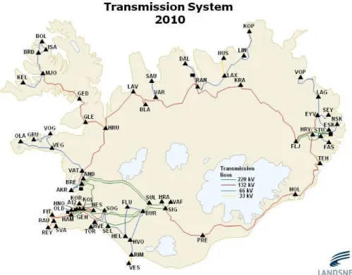
Virtually all inhabitants of Iceland, except those living on small islands off the coast and on remote farms, are connected to a single transmission system through six distribution networks. In 2010 the transmission system consisted of approx. 3,169 km of high voltages lines (operated at 33, 66, 132 and 220 kV) and around 70 substations and transformer stations (Figure 1 and Figure 2).
The Icelandic electricity system has expanded considerably during the last 15 years, mainly due to the increased production of power intensive industrial facilities and the commissioning of new ones. The total length of the Transmission (TSO) network in Iceland is approximately 3 169 km while the length of the Distribution (DSO) network (sum of all DSO) is approx. 22,565 km.
Two major transmission projects were completed in 2010. A 24.6 km, 132 kV, line was completed to provide a second connection between Nesjavellir Power Plant and the capital city area. The 140 MVA line is completely below ground. The TSO company, Landsnet also completed a 12 km, 66 kV, 28.5 MVA underground cable in the rural West Fjords area, with the aim of shortening the distance of the existing connection and decreasing supply disruptions.
During the period from 1995 to 2010, installed capacity increased from 1,049 MW to 2,579 MW and generation increased from 4,976 GWh to 17,059 GWh. The increase in electricity demand from power intensive industries has called for considerable investments in the transmission system. The long term investment needs of the Icelandic electricity sector are heavily dependent on the developments of power intensive industry. A medium or long term forecast for power intensive industries does not exist. There is uncertainty regarding investment needs due to increased demand from power intensive industries after 2012 but such investments may amount to ISK 5 to 7 billion per year.vii
Annual growth in the general public market is estimated at approximately 1.7% per year. The distribution system operators (DSOs) and the transmission system operator (Landsnet) create and publish investment plans for the general public market. According to Landsnet, medium and long-term investment and reinvestment needs for the transmission system are estimated at ISK 3 to 4 billion over the next three years (i.e. 2012 – 2015).viii
Iceland is an island with no interconnections to mainland Europe and therefore no international trade in electricity. Nearly all of Iceland’s electricity is produced from domestic and renewable sources. Production potential in Iceland is such that power intensive industries have been sought out to utilise Iceland’s electric supply. Generation from the geothermal and hydropower sources used in Iceland is base load and not subject to intermittency issues.
The Electricity Act stipulates that the TSO and the DSOs are responsible for maintaining and developing the transmission and distribution systems in an economic manner, taking into account security, efficiency, reliability of supply and the quality of electricity.ix
8
Figure 1:
Iceland Transmission Network
(Geographical)
x9
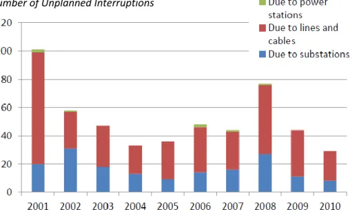
The Reliability of the electrical system in Iceland has improved over the last decade as can be seen in Figure 3 with the System Average Interruption Duration Index (SAIDI) indicators being as follows:
SAIDI (planned and unplanned interruptions) = 0.56 hours per customer SAIDI (planned interruptions) = 0.25 hours per customer
SAIDI (unplanned interruptions) = 0.31 hours per customer
Figure 3: System Performance of Electrical System in Iceland
xiiWith the current structure of the electrical Transmission Network in Iceland and the relatively undefined future need, it is imperative that developments and investment are made with thorough case by case assessment of the site specific needs. The sustainment and evolution of the system can’t only be made on technical merit or continuing current design philosophies but needs should be based on a clear outlook of the future. As electrical systems get higher attention as major economic driver and investments are scrutinized with a thicker acceptance lens, it is critical that investments are also based on life cycle costs and performance analysis, future climate data, industrial customer loads and recognizing other national economical drivers such as tourism, environmental sustenance and others.
Overview - European Electricity Lines
Majority of all Transmission line networks in the world have through history been constructed as overhead but although this may indicate that overhead is the preferred choice, the imbalance in volume
10
can easily be attributed to factors such as initial cost of investment, technical expertise to build and manage the overhead system, availability and complexity of application of underground transmission infrastructure. As the underground transmission systems and devices evolve and additional long-term investment considerations are taken into account, an upward shift in the proportion of underground versus overhead has taken place and that trend is expected to continue. Countries such as Holland, Germany and France now build a large portion of their transmission network with underground infrastructure. New transmission projects continue to being proposed, planned and built all over the world. The need for a water crossing, the desire to preserve open space and other aesthetic issues, and dealing with constrained right of way drives utilities to consider installing underground transmission in more and more cases. In some cases going underground is necessary in order to bring a project to completion, based on public pressure or constrained space. In addition, in more and more instances, underground or submarine transmission is becoming the first choice for longer distances.
Going underground with transmission has traditionally been a transmission owner's last resort because the cost of underground transmission was many times the cost of overhead transmission and maintenance and repair has proved costly and difficult. However, advanced cable technologies are being developed, installation techniques have expanded in terms of options and efficiency while cost factors have improved. xiii
Figure 4 below shows the proportions (2006 data) of overhead and underground in various countries of the world.
11
Overhead versus Underground Lines
Some of the critical technical requirements for the planning and design of building or upgrading an existing transmission line to either OHTL or UGTL is determined by several factors [Peter Nefzger, Ulf Kaintzyk, Joao Felix Nolasco, 2003]xv:
- Terminal Substations and line length
- Power to be transmitted in normal and emergency conditions - Type of transmission; AC vs. DC;
- Conductors, voltage, necessity of shield wires - Number of circuits
- Tower type, phase configuration
- Use of earth wires such as optimal ground wires - Maximum allowable losses
- Maximum acceptable levels of electrical and magnetic field
Beyond just electrical and system characteristics, there are also other factors such as terrain, environmental and governmental policy constraints. From a construction perspective, the land has to be secured as right-of-way (ROW) in both cases of OHTL and UGTL. Overhead lines are traditionally attached to insulators mounted on transmission structures which vary in height and design based on the voltage level and phase separation required between the conductors. The OHTL ROW typically spans 45m-85m for 132 kV to 220 kV whereas the UGTL ROW is typically 12-14m.
Figure 6: Underground Transmission Cable and Overhead Conductor
xviThe overhead line structure is preassembled and shipped to the construction location and placed on prefabricated buried steel tubes or concrete foundations. No additional digging is required on each site as the transmission line is build. Clearances need to be met when crossing roads, structures and other water bodies such as lakes or rivers. Maintenance of overhead lines is typically simple as they are easily
12
accessible from the surroundings. As overhead lines are exposed to dirt, moisture and lightning strikes, short circuits due to flash-overs or overvoltage surges do happen. These are typically transient faults and line condition can be restored with delayed reclosing after allowing the fault to clear. Line ratings are altered based on ambient temperature, loading, wind, sunlight etc. In essence, the overhead transmission system is more vulnerable to environmental externalities but is also restored to normal state in an expedient manner. Due to the distance between conductors of an OHL of several meters, their specific capacity is rather low compared to the specific inductivity. In a report by ECOFYS it is stated: “Given the extensive track record of OHL projects reliable information about specific costs is available. The cost for the conductors amounts to roughly one third of the total cost of a typical 2-system HV OHL.”xvii
Due to governmental and environmental pressures, newer tower designs have been in development to enable better aesthetic integration into the locality or terrain the OHTL is built in. Taken from a transmission technology assessment report from Ireland, Figure 7 below provides some examples of innovative design.
13
Figure 7: Conventional design (Donau-Mast) and new tower designs for improved
visual
impact
[Energienet.dk]
xviiiIn the case of the UGTL, trenches need to be dug where cables are laid either directly buried in ground or in ducts. The ducts can be either concrete encased or plastic pipes (PVC). The cables need joints in regular intervals because of weight and handling constraints for the typically heavy cable. For a recent 220 kV UGTL project in Denmark this was at 1200m intervalsxix.
Compared to underground cable, the specific capacitance is 12-26 times lower and the inductivity 3-4 times higher for an OHL. Reactive power does not contribute to the desired power transmission, but contribute to line loading and losses. Additionally, with long lines these charging currents become an engineering issue (energizing, testing, voltage profile, etc.). For that reason, the reactive power of an underground cable may need to be compensated at distances of as short as 40 km for 132/220kV lengthsxx by shunt reactors. However through accurate and unprejudiced network analysis and system design, including installation, the compensation length can be significantly increased for cable systems circuit lengths without reactive compensationxxi. Also the compensation design, if required, can be such that the compensation occurs at each end point of the cable or at its switching station. Thus it may not be unreasonable to expect that a single circuit cable at 132kV could be 120 km long without any compensation reactors required along the cable length (only at its endpoints).
The most important technical differences between OHTL and UGTL are insulation, thermal heating and installation techniques. In overhead lines, air acts as the insulating medium around the bare conductors attached to overhead structures. Based on the clearance requirements at different voltage levels and structure design, each conductor is spread wide apart from each other and the ground. In the case of underground lines heavy insulating medium has to be in place. Earlier generations of cable had oil impregnated paper as the insulation. The oil was borne in the cable via a pressured oil-duct through the center. Another type of insulation had high pressure fluid, e.g. nitrogen or oil, and was covered in a steel shielding. More recently cross-linked poly ethylene (XLPE) insulated cable has emerged as the most preferred cable for low to extra high voltage applications – see Figure 8 for an illustration of both types of cable. They are of a dry type and essentially maintenance free till they fail. These cables have totally different characteristics than the previous generation of cables and one need to be very careful when
14
utilizing life time and reliability statistics from historical cable installations as these would be mostly derived from the older types. Unfortunately, much of the statistics that is often presented when comparing overhead lines and underground cables have included these older types of cables.
Figure 8: Fluid-filled or Gas-filled Cable versus XLPE
xxiiAll conductor losses are directly due to the resistivity of the cable. In the case of underground cable, the losses are also due to induced current in the cable sheath and the insulation layer around the conductive medium. For overhead conductors air acts as the thermal conducting medium in overhead conductors to dissipate the heat whereas in the case of underground conductor, the soil can hinder the proper dissipation of heat generated in the cable. Typically XLPE underground cable conductors have a maximum operation temperature of at about 80 to 90 °C with an emergency operating temperature of about 130 °C.xxiii The selection of cable with lower resistivity, larger cross-section and transmitting energy at higher voltages are ways of mitigating the loss impact.
Costs for UGTL construction is significantly higher in urban areas as the existing infrastructure has to be supported and carefully handled whereas in rural areas mechanical diggers can be used without obstruction. In all cases when building a new UGTL, additional costs and care will be required to preserve the natural environment and existing infrastructure, e.g. rivers, roads, wetlands, lava fields, etc. When laying the cable inside trenches, it can be laid in a triangular bundle, or laid side by side. Each
15
technique has its own merit but can affect the cost, electrical conductivity (distance between cable and heat generated), future ability to maintain as well as fixing and restoration of faults. Some of the techniques used in the excavation of soil include horizontal drilling and running conduits, U or V shaped trenched (in rural land), pipe jacking and micro-tunneling. Trenches for UGTL are typically 1.5-2 m deep to keep them below the frost line.xxiv The other factor affecting the construction is joints and terminations. Vaults need to be dug when joints are required and they are traditionally over 3 m each way (length, breadth and height) or bigger. When underground sections of the cable has to be transitioned to an overhead section, termination structures have to be built for the continuity of the current flow and transition of construction.
These differences are all major considerations when building OHTL and UGTL and overall costs can be significantly different based on the choices made of each projects.
Life Cycle Cost Comparison
As discussed, historically transmission lines have predominantly been built overhead. The primary reasons for this have been availability of equipment, ease of construction and continued access and expertise. These construction costs for overhead lines are lower than for underground cables where civil costs are a big part of the initial investment. Digging trenches, building vaults and installing splice joints form a big portion of the complexity and cost of the underground installation. However, overhead lines require significant civil construction as well in terms of access roads and foundations platforms for the overhead structures.
When costs are considered while building a transmission line, the initial investment costs based on equipment selection, procurement and installation are not the only criteria that should be considered. Overall life cycle costs of electrical infrastructure also need to be considered such as maintenance, failures, losses, environmental impact etc.xxv The attribution of these costs are relevant too as they can be classified as Capital Expenditure (CapEx) and Operational Expenses (OpEx).
The costs provided below are approximate costs based on a culmination of project data collected across the industry and recent numbers provided by Landsnetxxvi. As such these are general values for rural surroundings and do not in any way represent a specific project. The actual costs of a specific project can vary based on local conditions and specific design and construction criteria selected. In the examples below, a general comparison of single circuit options with approximately 400MVA capacity at 220kV and 200MVA capacity at 132kV is made. If larger capacity is required the costs for installation of UGTL will go up more rapidly than for OHTL but at same time costs of losses would be much more favourable towards the Underground Cable.
In the first example, overhead lines have an expected life of about 60 years based on historical performance, while underground cables are often defined to have a lifetime of 40 years by design. The data presented is normalized to a 40 year period and a discount rate of 5.0% is used.
16
For loss costs an approximate price of €21.25 per MWh is used for the calculation (3.5 IKR/kWh) with an escalation of 3% per year – typically in Europe a cost of €40 per MWh are used for this purposes but costs in Iceland are lower. For this general example the amount of losses is roughly estimated as 2% with an average load of 200MVA for 220kV and 100MVA for 132kV.
Cost Category (132 kV) OH Cost/km M€/km UG Cost/Km M€/km Line Length Approx km Overhead M€ Underground M€ Ratio (UG/OH) Installation: 0.3 0.75 120 36 90 2.50 Losses 120 10 5.5 0.55 Total 46 95.5 2.08
Table 1: CapEx and Loss Costs for OHTL/UGTL for 132 kV – With Cable at 40 Year Life
Cost Category (220 kV) OH Cost/km M€/km UG Cost/Km M€/km Line Length Approx km Overhead M€ Underground M€ Ratio (UG/OH) Installation: 0.4 1.22 120 48 145.8 3.03 Losses 120 20 11 0.55 Total 68 156.8 2.31
Table 2: CapEx and Loss Costs for OHTL/UGTL for 220 kV – With Cable at 40 Year Life
However although Underground Cables are designed to last 40 years the modern XLPE type cables are generally expected to last much longer especially through well-developed precautionary measures designed to minimize overloading during their lifetime. For instance with the estimated life of UG cables at 60 yearsxxvii (true lifetime is expected to be even longer than that), the tables above would be revised to: Cost Category (132 kV) OH Cost/km M€/km UG Cost/Km M€/km Line Length km Overhead M€ Underground M€ Ratio (UG/OH) Installation: 0.3 0.5 120 36 60 1.67 Losses 120 10 5.5 0.55 Total 46 65.5 1.42
17 Cost Category (220 kV) OH Cost/km M€/km UG Cost/Km M€/km Line Length Approx km Overhead M€ Underground M€ Ratio (UG/OH) Installation: 0.4 0.81 120 48 97.2 2.03 Losses 120 20 11 0.55 Total 68 108.2 1.59
Table 4: CapEx and Loss Costs for OHTL/UGTL for 220 kV – With Cable at 60 Year Life
Dismantling costs are excluded in the above examples. These future costs are hard to estimate and may not be needed especially in the case of XLPE cable buried in the ground which may be better off left there rather than dug back up. Also when these costs are brought forward to present value they are very low.
Maintenance and failure remedial costs can be considered as OpEx and have to be considered over the life cycle. Typically OHTL requires significantly higher maintenance costs (as a ratio to initial capital cost) than underground, this cost needs to be considered of the life of the asset.
Routine maintenance of overhead lines can be conducted through visual inspection of observers on the ground or helicopter patrols. On the other hand underground equipment need monitoring devices installed to continually monitor the health of the cable and joints. This does pose different cost structures of each type of construction.
Approximate industry data is used to measure operating and maintenance costs of overhead and underground line. Operating and maintenance for OHTL is 1.5%-2% per year (of initial CapEx investment) and for underground it is 0.2%-0.4%xxviii. The lower limit is used in both cases (Tree trimming is not required in Iceland therefore lowering maintenance cost for OHTL and XLPE cables require much less maintenance than other types of cables) and this would result in approximate total costs as shown in table below.
Operating and Maintenance Costs (132 kV) Overhead M€ Underground M€ Ratio (UG/OH) Total Cost 21.6 4.8 0.22
Table 5: O&M Costs Comparison for 132 kV
Operating and Maintenance Costs (220 kV) Overhead M€ Underground M€ Ratio (UG/OH) Total Cost 28.8 7.8 0.27
18
As OpEx is direct expense and CapEx is depreciated over life cycle of assets, CapEx and OpEx expenses can be normalized further. For the simplicity of this analysis, we are considering them as equivalent expenditure over the life cycle of the assets and thus total costs can be considered as the aggregate of the two costs.
Total Costs Overhead M€ Underground M€ Overall Ratio (UG/OH) 132 kV 67.6 100.3 1.48 220 kV 96.8 164.6 1.70
Table 7: Total Life Cycle Cost Comparison for Cable with 40 Year Lifetime
In the more realistic case where the estimated life of UG cables is 60 years, the tables above would be revised to:
Total Costs Overhead M€ Underground M€ Overall Ratio (UG/OH) 132 kV 67.6 70.3 1.04 220 kV 96.8 116.0 1.20
Table 8: Total Life Cycle Cost Comparison for Cable with 60 Year Lifetime
As observed in the above ratios, although the initial investment in UGTL investment is higher, energy losses and life-cycle operating and maintenance costs will reduce the overall life-cycle ratios. Cost prudence with a longer term outlook can definitely ensure that investments on this magnitude can serve Iceland for the entire life cycle and future needs of the electricity grid.
In Iceland there is currently a 15% duty on electrical cable but not overhead wire. This cost is included in the above examples.
It should be recognized that the actual project costs incurred on specific project are heavily dependent on many specific factors and a full estimate should be performed for true comparison. The cost estimates provided above are for general comparison purposes only and is not recommended to be used as accurate estimates for specific projects.
Reliability and Availability of Power
Both overhead and underground transmission lines are reliable by design. The transmission systems, overhead or underground, are impacted differently; overhead systems are exposed to weather and volcanic ash while underground lines can be dug into. Soil reinforcement might be required for strength and stability of overhead structure and re-enforced concrete ducts can be used to counter unintentional damage to cables. Major earthquakes do occur in Iceland and in the case of one occurring; the underground transmission lines are often believed to be more vulnerable than overhead lines although evidence from previous earthquakes has not supported that theory. Failure patterns would vary by
19
location, design, weather, environment, awareness, standards and other factors. In the case of faults, locating faults in overhead lines is easier. Once located visually, the restoration process can start. Due to ease of accessibility, overhead failures on average can be fixed within few days (typically 1 day for minor failure and 5 days for major failure – average outage time for Landsnet’s 220 kV system is 6.9 hours per failurexxix but that may also include momentary outages). Historically underground failures take longer to locate and restoration of XLPE type can last 5-9 days based on factors such as condition of equipment, availability of replacements, ease of access, and expertise of workers.xxx This results in an unavailability of cables being higher than that of overhead lines, in this case by a factor of approximately two as is seen in table below. However, failure data for XLPE cables is being conservatively estimated as they have not been utilised for many years and failure rate is very low. The rate shown below for cable is estimated and should be considered a maximum failure rate. For a typical 120 km cable this would represent a single failure approximately every 30 years or twice in its 60 year lifetime.
Reliability Estimates Failure Probability Per year/100Km
Average Duration Hours
Unavailability Hours per year XLPE Underground Cable (Estimate) xxxi 0.03 168 5.0 220 kV Overhead Line (Landsnet report) xxxii 0.4 6.9 2.76
It should be noted that unavailability as shown in above table does not necessarily mean outages to customers as transmission systems are normally built in contingencies which allows for at least one failure to occur without causing customer being without power – this is the case with Landsnet’s system. Therefore the chances of two transmission system sections being unavailable at the same time are very low especially in the case of underground cables which have both a very random and low occurrences of failure. On the other hand, as overhead lines are more susceptible to storms the chances of simultaneous unavailability of two or more overhead lines is much higher which could result in large customer outages. Therefore the statistics shown in the table above seem overly favourable to overhead lines as their outages tend to happen during same episodes and they have many momentary outages that may cause voltage sags or short outages to customers.
Other Considerations
Safety
Safety around electrical equipment is the major concern of any company in the electrical sector around the world. Working on or around existing electrical equipment is a part of modern life for hydro workers and also for the general public. The risks are escalated in the case of high voltage transmission lines. Best safety standards have to be followed in the design of the lines and during the construction stages of the projects. Building residences under or over the ROW is not suggested. The biggest risk is the direct contact to energized lines and with ground at the same time. Fallen lines due to failure, lightning, wind, icing and/or storms can pose this threat if they continue to be energized. In the case of underground transmission, people or equipment can dig into the ground and contact risk can occur. Completely cordoning of ROWs, installing cable inside concrete encased ducts and adequate protection schemes are ways of mitigating or lowering these risks.
20
In general, many of the public safety concerns can almost be eliminated in the underground option. The weather and accessibility risks will continue to remain in any overhead design.
Right of Way
In general, building an UGTL is far more complex than building and OHTL. While some of the considerations are general in both types of construction, some are very unique to the underground option.
In the case of transmission corridor or Right of Way (ROW) selection, securement and construction execution, several key steps need to be considered that can have an impact on the overhead or underground lines during its life. In the selection stage of the path of the lines, many considerations do emerge. It can be in the form of pre-existing contamination, local habitat disruption unregistered private landfill that can form obstruction to the boring or drilling process. In the case of urban development, the ROW goes through local neighborhoods causing specific concerns amongst the neighboring constituencies. Water bodies in the path of the ROW can cause water erosion into the excavation site causing seepage into the ducts supporting cable. The other key issue is ensuring the underground ROW remains unharmed during its entire lifecycle. In underground construction, grading adjustments and heavy equipment digging can damage the duct structure and in turn damage the cable. This can cause significant outages to many people and have monetary impact on businesses and society in general. This requires acquiring proper land surveys, and having indemnity agreements and easements in place to control landscaping, tree-planting and storm water re-direction around the underground ROW.
EMF
Electo-magnetic fields (EMF) are created around cable or conductors when they carry current. With higher voltage the higher the strength of the electric field becomes and with higher current the higher the magnetic field becomes. These fields are prominent around the bare conductors in OHTL but are obstructed by the surrounding in the UGTL. At ground level, there is no electric field due to the shielding in the underground cable and the magnetic field falls off much more rapidly with distance than those from overhead power lines. However, the ground level magnetic fields can actually be higher close to the underground cable. According to the Public Service Commission of Wisconsin report on underground lines, “The strength of the magnetic field produced by a particular transmission line is determined by current, distance from the line, arrangement of the three conductors, and the presence or absence of magnetic shielding. Underground transmission lines produce lower magnetic fields than aboveground lines if the underground conductors are placed closer together which causes the magnetic fields created by each of the three conductors to cancel out some of the other’s fields. Magnetic fields are also strongest close to their source and drop off rapidly with distance. This phenomenon impacts the way the cables are installed in the ground, the closer the cables the lesser the EMF around but in reality bringing them too close will pose higher electrical limits to the amount of electricity that can be transported through the cable.”
Environment
As transmission lines are built in a certain area, the implications on the land and the natural habitat is permanent. In the case of underground, the land is excavated and deep rooted planting cannot be
21
placed on top of the right of way (ROW). Several steps during the design, construction and post construction phases can be taken to minimize the impacts. Some of the important factors are selection of equipment considering environmental sustainability, aesthetic design, timing of construction, restoration and species management.
During the replacement or upgrading of transmission lines, a few factors would definitely impact the surrounding environment and might add to the cost of building the line. A detailed transmission design analysis and construction estimate needs to consider this additional impact and also its monetary effect. For overhead lines, agriculture underneath is possible but there could be impacts such as soil erosion, increased weed and pest infestation, soil mixing, rutting and compaction. For underground lines, these direct impacts are minimized but still, the ROW land predominantly is secured but can still be used for general agricultural purposes. Waterways in the form of rivers, lakes, streams can also be impacted more for underground cable installation than overhead lines, however successful maneuvers around rivers in the construction of Kopasker–Bruarland 33kV underground cable in the 1990s show how that can be managed successfully.
Important aspect in Iceland is the abundance of untouched nature and scenery. It is considered valuable to have as much as possible of this extraordinary landscape remaining unchanged. Building very visible transmission lines can be quite contrary to that value statement as overhead lines can have strong visual impacts on the environment. That becomes particularly important in the Icelandic context, where landscape is frequently open, often with a wide horizon, and large wilderness areas are among the last remaining in Europe.
Tourism and local economy
Tourism is a big contributor to the Icelandic economy and the number of tourists coming into Iceland continued to grow over the last decade. The beautiful Icelandic landscape and natural habitat along with its unique climate are major drivers why people from all over the world come visit Iceland. According to a report published on Icelandic tourism in 2010, the share of tourism in Iceland’s GDP was 6%, having been between 4.4–6.0% since 2000. Tourism’s share in export revenue between 2009–2012 was between 18.8% and 23.5% according to measurements of the export of goods and services. Foreign visitors paid approximately ISK 238bn (€1.45B) to Icelandic companies in 2012 according to measurements of service transactions. The growth in spending was around 21% between 2011 and 2012. When, however, account is taken of price changes, the real growth was approx. 14%. At fixed-price levels, the spending of international visitors has increased by almost 30% from 2009 to 2012.xxxiii This trend is expected to increase in future years with increasing benefits to the Icelandic economy. It can be recognized that preserving the natural views and habitat is important to the country and building transmission lines underground is the natural choice in that regard. Studies have shown that this does affect people´s perception of unspoiled naturexxxiv. When evaluating options it is very important to consider the effect on this major economical driver. For example if a 220 kV transmission option similar to the example provided earlier in this report were built underground rather than overhead the total additional lifecycle cost could be approximately €20M. Per year that is an equivalent
22
cost of about €1M per year or less than 0.1% of the 2012 total economic value of tourism in Iceland at the 2012 level. In other words if the specific option chosen would cause a 0.1% reduction in tourism economic value or growth it may negate the other cost benefits of choosing that option.
Regulatory
The regulatory approval is crucial in this type of investment of this nature. It is widely accepted that electrical sector and assets are key economic drivers and prudent decisions needs to be made to enable long term sustainability of the system. The initial impact on rates needs to be assessed carefully with a outlook to the longer term investment returns considering all the different impacts discussed in the report. The other key aspect is striking a balance in stakeholders interests and recognizing the impact on businesses and economy as a whole. In Iceland the regulatory approval process is the responsibility of the National Energy Authority (NEA). Their role is to issue licenses for individual transmission projects based on merit, economic effectiveness and the approval of other relevant authorities. The NEA is therefore instrumental in ensuring that true economical comparison is performed on the options of constructing Underground Cables vs. Overhead Lines and that not only construction costs are being used as a decision driver as often is the tendency from a TSO perspective.
23
Conclusion and Recommendations
As the Commission of European Community eloquently mentions in their report: “The issue of undergrounding of overhead lines is not new, as underground cables have been used for many decades for low and medium voltage lines in urban areas. As more environmental considerations started to be taken into account in the construction of electricity networks since the 1970’s, underground cables started to be used in high voltage and extra high voltage lines, but in limited cases owing to their high cost”.xxxv
Based on the life-cycle cost estimate provided in this report, it is evident that undergrounding transmission lines is a financially viable choice for long term return on investment. This option has other benefits such as enhanced safety, lower environmental impact, aids in the maintenance of Iceland’s natural habitat and may support the growth of the tourism industry. When evaluating options, such as these that are discussed in the report, it is important to consider all life-cycle costs and not only initial construction costs. Only then can a true comparison be made.
Although the comparison shown in this report is of general nature and it is necessary that case by case analysis is performed for individual projects the following conclusions can be made:
“The life-cycle costs for underground cable at 132/220 kV can be expected to be about 4-20% more costly than 132/220 kV overhead lines respectively and can therefore be a very viable option when other economic drivers are considered.”
The above statement assumes similar lifetime (60 years) for both the underground cable and the overhead line. This assumption may be contested as there have not been many years of experience with the modern types of cables but it is generally believed they will last much longer than their 40 years of design life. Similarly overhead lines have been shown to last longer than their generally accepted lifetime of 50 years although in many cases they are replaced prematurely for other reasons than deterioration. For instance some of the 132 kV lines in Iceland currently being utilized for the national ring transmission are only about 40 years old. This could also be the case for prospective overhead lines that may be built in controversial scenic areas. It is possible that they will be forced underground much before their 60 year lifetime is reached resulting in non-optimal investment.
24
References
i STUDY ON THE COMPARATIVE MERITS OF OVERHEAD ELECTRICITY TRANSMISSION LINES VERSUS UNDERGROUND
CABLES, ECOFYS, 2008
ii Underground Electric Transmission Lines, Public Service Commission of Wisconsin, 2011
iii Underground Electric Transmission Lines, Public Service Commission of Wisconsin, 2011 iv
Underground vs. Overhead: Power Line Installation-Cost Comparison and Mitigation, FRANK ALONSO AND CAROLYN A. E. GREENWELL, 2013
vhttp://rarik.is/frettir/frettir/milljonatjon-a-nordurlandi vi
Report on Regulation and the Electricity Market, ORKUSTOFNUN (National Energy Authority), 2011
vii
Report on Regulation and the Electricity Market, ORKUSTOFNUN (National Energy Authority), 2011
viii Report on Regulation and the Electricity Market, ORKUSTOFNUN (National Energy Authority), 2011 ix
Report on Regulation and the Electricity Market, ORKUSTOFNUN (National Energy Authority), 2011
x
Report on Regulation and the Electricity Market, ORKUSTOFNUN (National Energy Authority), 2011
xihttp://www.landsnet.is/?pageid=172f0fd0-76d7-4eb2-b78a-1f9b3ad41cc6, Landsnet (Iceland TSO) Website xii
Report on Regulation and the Electricity Market, ORKUSTOFNUN (National Energy Authority), 2011
xiii
High Voltage XLPErformance of Cable Technology, Björn Dellby, Gösta Bergman, Anders Ericsson, Johan Karlstrand, ABB Review, 2011
xiv
STUDY ON THE COMPARATIVE MERITS OF OVERHEAD ELECTRICITY TRANSMISSION LINES VERSUS UNDERGROUND CABLES, ECOFYS, 2008
xv
Overhead Power Lines: Planning, Design, Construction, Peter Nefzger, Ulf Kaintzyk, Joao Felix Nolasco, Springer 2003
xvi
Referred: Overhead Vs Underground, Tri-state Generation and Transmission Association, Touchstone Energy Co-op, 2011. Photo courtesy of Georgia Transmission Corporation
xviiSTUDY ON THE COMPARATIVE MERITS OF OVERHEAD ELECTRICITY TRANSMISSION LINES VERSUS
UNDERGROUND CABLES, ECOFYS, 2008
xviii http://energinet.dk/DA/ANLAEG‐OG‐PROJEKTER/Anlaegsprojekterel/Nettilslutning‐af‐Anholt‐havmoellepark/ Sider/Anlaegget.aspx, 2012 xix http://energinet.dk/DA/ANLAEG‐OG‐PROJEKTER/Anlaegsprojekterel/Nettilslutning‐af‐Anholt‐havmoellepark/ Sider/Anlaegget.aspx, 2012
xxSTUDY ON THE COMPARATIVE MERITS OF OVERHEAD ELECTRICITY TRANSMISSION LINES VERSUS
UNDERGROUND CABLES, ECOFYS, 2008
xxi
LONG LENGTH EHV UNDERGROUND CABLE SYSTEMS IN THE TRANSMISSION NETWORK, M. DEL BRENNA, F. DONAZZI (*), A. MANSOLDO PIRELLI CAVI E SISTEMI ENERGIA SPA, 2004
xxii Underground Electric Transmission Lines, Public Service Commission of Wisconsin, 2011 xxiii
Underground Electric Transmission Lines, Public Service Commission of Wisconsin, 2011
xxiv Underground Electric Transmission Lines, Public Service Commission of Wisconsin, 2011 xxv
Variation of Life Cycle Costs for Overhead Transmission Line and Underground Transmission Cable, Preet Khandelwal, 2013
xxvi
Landsnet Report: “Lagning raflína í jörð”, January 2013
xxvii Undergrounding high voltage electricity transmission, The technical issues, National Grid, 2007 xxviii
Underground Electric Transmission Lines, Public Service Commission of Wisconsin, 2011
xxix
Landsnet Report: “Lagning raflína í jörð”, January 2013
xxx Underground Electric Transmission Lines, Public Service Commission of Wisconsin, 2011 xxxi
Joint paper: Feasibility and technical aspects of partial undergrounding of extra high voltage power transmission lines, ENTSO-E and Europacable, 2010
xxxii Landsnet Report: “Lagning raflína í jörð”, January 2013 xxxiii
Tourism in Iceland in figures, Oddný Þóra Óladóttir, April 2013
xxxiv
Áhrif Hólmsárvirkjun á ferðamennsku og útivist, Anna Dóra Sæþórsdóttir and Rögnvaldur Ólafsson, 2012


![Figure 7: Conventional design (Donau-Mast) and new tower designs for improved visual impact [Energienet.dk] xviii](https://thumb-us.123doks.com/thumbv2/123dok_us/10252465.2930616/13.918.110.813.108.345/figure-conventional-design-donau-designs-improved-visual-energienet.webp)



