Domain Isolation in a Multi-Tenant
Software-Defined Network
School of Electrical Engineering
Thesis submitted for examination for the degree of Master of Science in Technology.
Espoo 15.4.2015
Thesis Supervisor:
Prof. Jukka Manner, Aalto University, Finland
Thesis Instructor:
Author: Alireza Ranjbar
Title: Domain Isolation in a Multi-Tenant Software-Defined Network
Date: 15.4.2015 Language: English Number of pages: 10+97
Department of Communications and Networking
Professorship: Networking Technology Code: S-38
Supervisor: Prof. Jukka Manner, Aalto University, Finland
Instructor: Kristian Slavov M.Sc. (Tech.), NomadicLab, Ericsson Research, Fin-land
Software-Defined Networking (SDN) has evolved as a new networking paradigm to solve many of current obstacles and limitations in communication networks. The SDN technology is going to be implemented in multi-tenant environments like data centers where several customers, which are called “tenants”, share network resources. In fact, the integration of SDN allows tenants in a shared network to have higher levels of control over available resources. While this approach has several advantages, the isolation between the tenants of a shared network becomes a vital factor which has not been discussed clearly so far. This thesis discusses multi-tenancy and explains current isolation approaches in a multi-tenant SDN. For increasing isolation between tenants, this thesis proposes a scalable solution that provides traffic isolation, address space isolation, control isolation and performance isolation. In the new system architecture, tenants are not limited to their own networks and they are able to make interaction with each other and external resources. Indeed, while tenants are isolated from each other, they are allowed to access special services offered by other tenants or external services outside of a shared network.
The evaluation of the prototype proves that the new architecture provides a high level of isolation in a multi-tenant SDN and it is scalable enough to be implemented in large networks with millions of tenants.
Keywords: Domain, Multi-Tenancy, Policy, SDN, OpenFlow, Traffic Isolation, Packet Rewriting, Address Space Isolation, Control Isolation, Moni-toring
Acknowledgements
I am grateful to all of those who supported me throughout this thesis work. I would like to thank my supervisor, Prof. Jukka Manner for reviewing my thesis and giving me valuable feedbacks. Also, I would like to give my special thanks to Prof. Tuomas Aura who guided me throughout this thesis work. I deeply appreciate his constant support and excellent suggestions during this work.
I would like to show my gratitude to my instructor, Kristian Slavov, for sup-porting me throughout this work. Special thanks to Bengt Sahlin for providing me an opportunity to work on my field of interest in Ericsson Research, NomadicLab. Also, I would like to thank all my colleagues from NomadicLab particularly Patrik Salmela, Abu Shohel Ahmed, Oscar Novo, Miika Komu and Kazi Wali Ullah for guiding me and creating such a friendly and enjoyable working environment.
Last but not least, I would like to thank my family who supported me morally all through my life.
Espoo, April 2015 Alireza Ranjbar
Abstract . . . ii Acknowledgements . . . iii Contents . . . iv 1 Introduction 1 1.1 Research Goals . . . 2 1.2 Contributions . . . 2 1.3 Limitations . . . 3
1.4 Structure of the Thesis . . . 3
2 Software Defined Networking 4 2.1 SDN Architecture . . . 4 2.1.1 Application Plane . . . 4 2.1.2 Controller Plane . . . 6 2.1.3 Data Plane . . . 6 2.1.4 Management . . . 7 2.2 OpenFlow Specification . . . 8 2.2.1 Flow Table . . . 8 2.2.2 Matching . . . 10 2.2.3 OpenFlow Protocol . . . 11 2.2.4 Secure Channel . . . 12 2.3 Chapter Summary . . . 12 3 Isolation in a Multi-Tenant SDN 13 3.1 Multi-Tenancy in SDN . . . 13
3.1.1 SDN Provider with Connected Tenant Applications . . . 13
3.1.2 SDN Provider with Directly Connected Tenant Controllers . . 14
3.1.3 SDN Provider with Non-Recursively Connected Tenant Con-trollers . . . 15
3.1.4 SDN Provider with Recursively Connected Tenant Controllers 16 3.2 Current Isolation Techniques in a Multi-Tenant SDN . . . 16
3.2.1 Slicing . . . 17
3.2.2 Encapsulation . . . 17
3.2.3 Packet Rewriting . . . 17
3.3 Available Multi-Tenant SDN Solutions and their Isolation Approaches 19 3.3.1 FlowN . . . 19
3.3.2 Splendid Isolation . . . 20
3.3.3 FlowVisor . . . 20
3.3.4 AutoSlice . . . 22
3.3.5 OpenVirtex . . . 23
3.4 Chapter Summary . . . 23
4 Proposed System Design 25 4.1 Design Goals . . . 25
4.2 Design Pattern . . . 26
4.3 Principles . . . 27
4.3.1 SDN Provider . . . 27
4.3.2 Tenant . . . 27
4.3.3 Tenant Network Domain . . . 27
4.3.4 Policy . . . 28 4.4 Architectural Components . . . 28 4.4.1 Northbound Interface . . . 29 4.4.2 Service Manager . . . 29 4.4.3 DHCP Server . . . 30 4.4.4 ARP Handler . . . 30 4.4.5 Isolation Manager . . . 30 4.4.6 Routing Manager . . . 31 4.4.7 Monitoring . . . 33
4.5 Communication Patterns in the System Architecture . . . 33
4.5.1 Intra-Tenant Communications . . . 33
4.5.2 Inter-Tenant Communications . . . 36
4.5.3 External Communications . . . 40
4.6 Chapter Summary . . . 44
5 Implementation of the Prototype 45 5.1 Implementation Environment . . . 45
5.2 Implementation of the Northbound Interface . . . 46
5.3 Implementation of the Service Manager . . . 49
5.4 Domain Discovery Mechanism . . . 51
5.4.1 Domain Discovery for Northbound Requests from Tenants . . 51
5.4.2 Domain Discovery for Flow Requests from the Data Plane . . 51
5.5 Implementation of the DHCP Server . . . 53
5.5.1 Host Detection with the DHCP Server . . . 53
5.5.2 Expired Leased Addresses . . . 53
5.6 Isolation Mechanism in the Prototype . . . 54
5.6.1 Rule Matching . . . 54
5.7 Forwarding at the Data Plane . . . 56
5.8 Implementation of Monitoring . . . 61
5.8.1 sFlow-RT . . . 62
5.8.2 Protection Application . . . 62
5.8.3 Monitor Manager . . . 62
5.9 Implementation Issues and Challenges . . . 62
6 Evaluation and Experimental Results 64
6.1 Analysis of Isolation Enforcement . . . 64
6.1.1 Traffic Isolation . . . 64
6.1.2 Address Space Isolation . . . 64
6.1.3 Control Isolation . . . 65
6.1.4 Performance Isolation . . . 65
6.2 Functional Testing . . . 65
6.2.1 Test Scenario 1: Isolation in Intra-Tenant Communications . . 66
6.2.2 Test Scenario 2: Isolation in Inter-Tenant Communications . . 67
6.2.3 Test Scenario 3: Isolation in External Communications . . . . 69
6.2.4 Test Scenario 4: Performance Isolation . . . 71
6.3 Scalability . . . 73
6.3.1 Scalability at the Core Network . . . 73
6.3.2 Scalability in IP Address Assignment . . . 74
6.4 Control Traffic Overhead . . . 75
6.4.1 Size of OpenFlow Messages . . . 75
6.4.2 Control Overhead in the Prototype . . . 79
6.5 Latency of Rule Matching Process . . . 80
6.6 Discussion . . . 81
6.7 Chapter Summary . . . 82
7 Conclusion 84
Appendices 92
2.1 SDN Architecture . . . 5
2.2 Service Abstraction Layer in the OpenDaylight controller . . . 7
2.3 Simplified diagram of flow matching in an OpenFlow-enabled device . 10 3.1 SDN provider with application tenants . . . 14
3.2 SDN provider with SDN tenants connected directly to the data plane 15 3.3 SDN Provider with Non-Recursively Connected Tenant Controllers . 15 3.4 SDN Provider with Recursively Connected Tenant Controllers . . . . 16
3.5 Packet rewriting at the controller plane . . . 18
3.6 Packet rewriting at the data plane . . . 18
3.7 FlowN Architecture . . . 19
3.8 Slicing approach (topology slicing) in FlowVisor . . . 21
3.9 Architecture of AutoSlice . . . 22
3.10 Isolation at the controller and data planes in OpenVirtex . . . 23
4.1 Design pattern . . . 27
4.2 System Architecture . . . 29
4.3 Routing in the System Architecture . . . 32
4.4 The operational flow for the intra-tenant communication . . . 35
4.5 An example of the service advertisement for inter-tenant communi-cations . . . 36
4.6 The operational flow for the inter-tenant communication . . . 39
4.7 The operational flow for the communication to the external network . 41 4.8 The operational flow for the communication from the external network 43 5.1 The operational states of a bundle in the OSGi framework . . . 46
5.2 Domain management in the service manager . . . 50
5.3 Implemented algorithm for finding the destination domain . . . 52
5.4 Host detection using the DHCP server . . . 54
5.5 Proactive rule installation at the core network . . . 57
5.6 Reactive forwarding using the routing manager at the edge of the network . . . 59
5.7 Message diagram for monitoring process in the prototype . . . 61
6.1 Test network for intra-tenant communications . . . 66
6.2 A packet captured between end-hosts A-1 and A-2 at the core network 67 6.3 A packet captured between end-hosts B-1 and B-2 at the core network 67 6.4 A packet captured between end-hosts C-1 and C-2 at the core network 67 6.5 Test network for inter-tenant communications . . . 68
6.6 A captured packet on the link between end-host B-1 and edge switch S1 . . . 68 6.7 A captured packet on the link between edge switch S1 and core switch
S3 . . . 69 6.8 A captured packet on the link between edge switch S3 and end-host
A-1 . . . 69 6.9 The output of Iperf server on the end-host A-1 . . . 69 6.10 Test network for external communications . . . 70 6.11 A packet captured on the link between switch S1 and S2. The source
of the packet is end-host A-1 . . . 71 6.12 A packet captured on the link between switch S1 and S2. The source
of the packet is end-host B-1 . . . 71 6.13 A packet captured on the link between the core switch S2 and the
edge switch S1. The destination of the packet is end-host A-1 . . . . 71 6.14 A packet captured on the link between the core switch S2 and the
edge switch S1. The destination of the packet is end-host B-1 . . . . 71 6.15 Testing the prototype without the monitoring module . . . 72 6.16 Testing the prototype by enabling the monitoring module . . . 72 6.17 A sample network for testing the scalability . . . 73 6.18 The number of flow entries at the ingress edge switch and the core
switch . . . 74 6.19 Control messages (OpenFlow) for processing a new flow request in
our prototype . . . 79 6.20 The amount of control traffic based on the number of new flow requests 80 6.21 The latency of rule matching technique for installing forwarding rules 81 7.1 Multi-location approach for future work . . . 86
2.1 An example of the REST API definition in the OpenDaylight
con-troller . . . 5
2.2 Match fields in the flow table . . . 9
5.1 REST request for registering a tenant . . . 47
5.2 REST request for setting a subnet . . . 48
5.3 REST request for creating a policy group . . . 48
5.4 REST request for adding rules to a policy group . . . 48
5.5 REST request for service advertisements . . . 49
5.6 REST request for setting network configurations . . . 49
5.7 Forwarding rules at the core of the network . . . 56
5.8 Match fields of forwarding rules at the edge of the network . . . 58
5.9 Actions for forwarding rules at the edge of the network (the source and destination end-hosts are not connected to the same edge switch) 60 5.10 Actions for forwarding rules at the edge of the network (the source and destination end-hosts are connected to the same switch) . . . 60
6.1 The number of available IP addresses and port numbers for different types of communications . . . 75
6.2 Size of header fields for all transmissions between the controller and the switches . . . 76
6.3 Size of Packet-in message . . . 76
6.4 Size of Packet-out message . . . 77
6.5 Size of Flow-Mod message for different types of flows . . . 78
6.6 Size of Barrier messages . . . 78
6.7 Size of Flow-Removed message . . . 78
6.8 Total control overhead for handling a new flow . . . 79
Abbreviations
ACK Acknowledgment
API Application Programming Interface ARP Address Resolution Protocol
CFI Canonical Format Identifier
CPU Central Processing Unit
CPX Controller Proxy
CRC Cyclic Redundancy Check
DHCP Dynamic Host Configuration Protocol HTTP Hypertext Transfer Protocol
ICMP Internet Control Message Protocol
ID Identifier
IP Internet Protocol
JAX-RS Java API for RESTful WEB Services JSON JavaScript Object Notation
LLDP Link Layer Discovery Protocol
LXC Linux Container
MAC Media Access Control
MM Management Module
MPLS Multiprotocol Label Switching
NAT Network Address Translation
NIC Network Interface Card
OSGi Open Services Gateway initiative
PCP Priority Code Point
QOS Quality of Service
REST Representational State Transfer
RFC Request for Comments
SAL Service Abstraction Layer
SDN Software-Defined Networking
sFlow sampled Flow
sFlow-RT sFlow Real Time
SNMP Simple Network Management Protocol
SSL Secure Sockets Layer
TCP Transmission Control Protocol TLS Transport Layer Security
ToS Type of Service
UDP User Datagram Protocol
VID Virtual Local Area Network Identifier
VIF Virtual Interface
VLAN Virtual Local Area Network
VM Virtual Machine
VXLAN Virtual Extensible LAN
Introduction
During the past few years, Software-Defined Networking (SDN) has emerged as a new networking paradigm by decoupling the control layer in the network from the forwarding layer. The separate centralized controller has led to better virtualization and programmability in today’s networks. In the architecture of SDN, applications send forwarding requests to the controller by the Application Programming Interface (API) commonly called northbound API. Consequently, the controller installs the necessary forwarding rules in the network elements in the data plane. The OpenFlow protocol has been accepted as the first standard protocol for communication between the controller plane1 and the data plane. The use of OpenFlow allows the SDN
controller to control different networking devices from different vendors with an open standard interface.
Both the academia and the industry are investing in the development of SDN. Ericsson, Google, Juniper and Cisco are few of the vendors that have contributed to the development of SDN and programmable networks. Despite all the advantages of SDN, the implementation of multi-tenancy with SDN is still a research problem. Multi-tenancy is an appealing feature of todays networks which allows different cus-tomers and organizations share the same resources of a SDN network while they are logically isolated from each other. Since the resources are shared, isolation becomes one of the most important requirements of multi-tenant SDN networks [12,14]. In SDN, we need isolation at both of the controller and data planes. Consequently, a combination of different isolation techniques should be used to provide effective isolation at both layers. On the other hand, isolation is a general concept and it needs to be explored in every aspect. For instance, we can have traffic isolation between tenants which limits tenants to only accessing their own traffic, or we may need performance isolation which restricts tenants from affecting the performance of other tenants in a shared network.
Several solutions have been implemented for bringing multi-tenancy into SDN networks. FlowVisor [39] is one example which provides multi-tenancy by making slices of a shared network for different tenants. Another example is FlowN [38], which allows to define several tenant networks by using encapsulation technique. However, there is not any comprehensive research about the possible configurations for a multi-tenant SDN. Likewise, different isolation approaches in a multi-tenant SDN have not been discussed extensively so far. Therefore, during this thesis, we
1According to [3], the control plane in SDN is called the controller plane
investigate the possible configurations for a multi-tenant SDN and then, we explore the different isolation techniques that have been used in the available multi-tenant SDN solutions. In addition, we propose a new architecture for providing higher levels of isolation in a multi-tenant SDN. While our solution provides isolation for tenants, it increases interoperability between tenants and it allows tenants to connect to the available services outside of a shared network.
1.1
Research Goals
This thesis mainly focuses on isolation in a multi-tenant SDN. The goals of the thesis are:
• Defining and explaining possible configurations in a multi-tenant SDN. At first, the concept of multi-tenancy in SDN is discussed and then the possible configurations between tenants and a service provider are explained.
• Surveying the current isolation techniques in a multi-tenant SDN to under-stand the design space. This includes a motivation for isolation in a multi-tenant SDN and an analysis of the state-of-the-art isolation techniques.
• Designing a new architecture to enhance isolation in a multi-tenant SDN. Our solution covers various isolation requirements in a multi-tenant SDN.
• Implementing a prototype of the designed architecture and evaluating the func-tionality and the performance of the prototype. The prototype is implemented on the OpenDaylight controller.
1.2
Contributions
The first contribution of this thesis is to discuss possible configurations in a multi-tenant SDN network. We consider four different types of interaction between multi-tenants and a service provider in a SDN network. Furthermore, we explain the isolation approaches in existing multi-tenant SDN solutions.
The next contribution of this thesis is to propose and implement a scalable solution which provides traffic isolation, address space isolation, control isolation and performance isolation between the tenants of a shared network. The traffic isolation provides isolation between different flows at the data plane and the address space isolation allows to have overlapped addresses between tenants. With the control isolation, we allow tenants to securely join the network and make their own configurations. Moreover, we have integrated the monitoring feature in our architecture which leads to the performance isolation between tenants. Additionally, our solution increases the isolation level between tenants by removing the broadcast ARP requests and allowing tenants to join the network using a DHCP server.
While our solution provides isolation, it allows tenants to make connection with offered services by other tenants or external services outside of a shared network. Indeed, tenants are not limited to their own networks and we have provided a possibility for tenants to interact with each other and with the external resources.
Although we have implemented our architecture on the OpenDaylight controller, it can be extended to other SDN controller platforms.
1.3
Limitations
Our architecture is mainly based on the OpenFlow 1.0 specification. However, the OpenFlow protocol is not mature and has several drawbacks. OpenFlow does not include features to configure the network elements in the data plane from the con-troller plane, so we need to configure the devices manually. Moreover, it does not provide effective QOS features, and we rely on available capabilities. OpenFlow 1.3, supports more QOS features, and the OpenDaylight controller implements this version, but it is not yet supported by the Open vSwitch at the time of writing of this thesis. Our approach is also based on the Open vSwitch features2, and so it is
not possible to change it to the other virtual switch implementations.
1.4
Structure of the Thesis
In chapter 2, we explain all details about SDN that are used in the subsequent chapters. The architecture of SDN networks will be discussed and the OpenFlow protocol will be explained in detail in this chapter. In the next chapter, we intro-duce the possible configurations for a multi-tenant SDN. Moreover, the isolation approaches in existing multi-tenant SDN solutions will be explained. In chapter 4, we explain our new architecture and the functionality of our solution. The details of each component in our architecture will be discussed in this chapter. We start to explain about the implementation of our prototype in chapter 5. The structure of our prototype will be explained in detail in this chapter. In chapter 6, we evaluate our approach for the different isolation requirements and we run several test scenar-ios for testing the functionality of our solution. Also, we evaluate the solution in terms scalability, overhead and latency and we discuss about the the advantages and the disadvantages of our proposed solution in this chapter. In the last chapter, we summarize our work based on the topics discussed throughout the thesis and make conclusion in this chapter. Additionally, the possible directions for future works will be introduced in the last chapter.
Software Defined Networking
Today’s networks are growing in size, the amount of traffic and more complex fea-tures. While available technologies are limited to address the current limitations, SDN has emerged as a new networking paradigm to solve many of current obsta-cles in today’s networks. SDN removes the complexity and provides an abstract view of the network with a central control point. In this way, we have a central controller over the network which eases the management of networking resources. The programmable and the open nature of SDN leads to a high level of innova-tive and independent developments. Also, a centralized view of the network allows the controller to define uniform security policies over network resources [1]. In this chapter, at first we explain about the architecture of SDN and different components in the SDN architecture. Then, we continue this chapter by explaining the use of OpenFlow protocol in SDN and the definition of different messages in this protocol.
2.1
SDN Architecture
The SDN architecture includes the application plane, the controller plane, the data plane and the management. The architecture of SDN is depicted in Figure 2.1. The application plane communicates with the controller plane through the northbound API and the controller plane connects to the data plane with the southbound API [3, 1]. The first standard protocol for SDN networks is OpenFlow [2] protocol which is used as a southbound API for connecting the controller plane to the data plane.
2.1.1
Application Plane
The application plane consists of one or more applications that send their requests to the controller with the northbound interface. Network services are defined at the controller plane and they provide APIs for applications to use the available function-alities without considering the complexity of the underlying network. Consequently, it is possible to offer several services for different purposes through the northbound APIs [3]. The northbound interface is defined by open APIs to provide the common interface between different vendors.
One of the popular APIs that has been implemented widely is Representational State Transfer API (REST API) [20]. The SDN controller uses the REST API to provide an interface for communication with the application plane. By using the
Figure 2.1: SDN Architecture
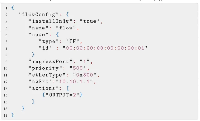
REST API, the SDN controller is able to hide the details of the network components and provides the main roles and major features. It shows an abstract view of avail-able services to the application layer using the REST API and hides the complexity of the network services [20]. In the Opendaylight controller, the REST API can be defined in the JSON or XML format. Table 2.1 shows an example of the REST API definition for the flow configuration in JSON format after sending a GET command to the OpenDaylight controller [17].
Table 2.1: An example of the REST API definition in the OpenDaylight controller
1 { 2 " f l o w C o n f i g ": { 3 " i n s t a l l I n H w ": " true ", 4 " name ": " flow ", 5 " node ": { 6 " type ": " OF ", 7 " id " : "0 0:0 0:0 0:0 0:0 0:0 0:0 0:0 1" 8 } 9 " i n g r e s s P o r t ": "1", 10 " p r i o r i t y ": "5 0 0", 11 " e t h e r T y p e ": "0x8 0 0", 12 " n w S r c ":"1 0.1 0.1.1", 13 " a c t i o n s ": [ 14 {" O U T P U T =2"} 15 ] 16 } 17 }
2.1.2
Controller Plane
The controller plane provides a logically centralized view of the underlying network. In fact, the SDN controller at the controller plane becomes the network intelligence to control the entire network resources from a central point. The SDN controller works with the abstract view of the network resources and since the controller is implemented as a software solution, it is possible to implement a variety of services for different applications based on the available network resources. Today, we have many controllers operating on this layer such as NOX, POX, Opendaylight and Floodlight. The internal functional processes of these controllers are different but most of them allow programmers to define new services based on their structural languages such as Java, Python or C/C++ [3].
At the following, we briefly explain the functionality and the structure of the OpenDaylight controller as an example to clarify the operation of the SDN con-trollers.
OpenDaylight
OpenDaylight is a joint project between various vendors to provide a reference frame-work and an open source controller. It allows programmers to frame-work on an open source project in an open community to develop business and technical subjects. According to [16], the mission goal of this group is: “Facilitate a community-led, industry-supported open source framework, including code and architecture, to accel-erate and advance a common, robust Software-Defined Networking platform”.
OpenDaylight is a modular controller based on Service Abstraction Layer (SAL). Indeed, the modular design by SAL leads to the definition of rich services for mod-ules and applications. Network services are deployed in SAL based on the features presented by the southbound plugins. Moreover, OSGi [28] is used as a component based framework to dynamically develop network services as new modules on the controller. Generally, SAL provides services like Device Discovery or Packet Data and OSGi uses these services for making new modules. Figure 2.2 illustrates the architecture of the OpenDaylight controller based on SAL [17].
2.1.3
Data Plane
The data plane consists of one or more network elements. Each network element includes a set of traffic processing and forwarding functions. This layer is responsible for providing appropriate virtualization, security, connectivity, quality and availabil-ity for processing the customer’s traffic. Each network element contains a virtualiza-tion component named the virtualizer. The virtualizer on the network elements is responsible for providing an abstract view of resources for the controller and enforc-ing the policy. The data plane receives instructions and forwardenforc-ing requests from the controller and it cannot process the traffic by itself. However, it is possible that the controller delegates specific capabilities to the data plane [3].
At the following, we briefly explain Open vSwitch as an example of network elements working at the data plane.
Figure 2.2: Service Abstraction Layer in the OpenDaylight controller
Open vSwitch
The Open vSwitch [8] is a software solution that provides connection between VMs and physical devices. Unlike physical hosts that communicate with NIC cards, VMs use Virtual Interfaces (VIFs) and virtual switches provide the connection between VIFs and physical interfaces. Furthermore, the Open vSwitch has the ability to be controlled by the SDN controller using the OpenFlow protocol. The operation of the Open vSwitch is based on two fundamental elements: kernel resident “fast path” and userspace “slow path”. Forwarding operations including packet look up, counting and forwarding are implemented by the fast path. Forwarding logic operations such as: MAC address learning, load balancing and configurations are implemented with the slow path. Additionally, management protocols like OpenFlow are implemented in the slow path [33].
2.1.4
Management
The Management is responsible for all management functionalities in all layers. As it is demonstrated in Figure 2.1, this layer is connected to the application plane, the controller plane and the data plane. Generally, the management layer is re-sponsible for implementing functionalities that are not supported by other layers. Also, the management is responsible for tasks that other layers are prohibited from implementing, for example, according to the policy. The management consists of SDN specific tasks such as defining the policies between the service provider and clients and the configuration and initialization of separate SDN units. Moreover, the responsibilities of this layer include the arrangement of information about the handoff points of the data plane, identification, credentials and protocols between physical and logical SDN units [3].
2.2
OpenFlow Specification
OpenFlow [1, 2] is the first standard protocol for interaction between the controller plane and the data plane. It allows the controller and the network elements of the data plane to transfer the configuration and statistical messages directly. The OpenFlow benefits from the concept of flows and in OpenFlow, each flow is processed according to the pre-defined match rules. Since OpenFlow is based on per flow analysis, it provides high granular control which leads to react in real-time to changes in the applications, users and sessions.
2.2.1
Flow Table
The flow table is one of the major parts of the OpenFlow-enabled switches. Each entry in the flow table of OpenFlow 1.0 includes a set of fields. The most relevant fields are1: Header (Match) Fields, Counters, Timeouts, Priority and Actions. At
the following, we explain each field briefly.
Header (Match) Fields
An incoming packet to the switch matches according to the header fields illustrated in Table 2.2. Each of these 12-tuples can be a specific or ANY value. In case of choosing ANY as a value for one field, it matches all possible values [58].
Counter
Counter field indicates statistics information for each table, flow, port and queue on the switch. This field includes the amount of traffic (in bytes) and the number of received, transmitted and dropped packets. Also, it includes information about the possible errors like CRC, overrun and frame errors.
Timeouts
Each flow in the flow table has an Idle and Hard timeout. The idle timeout declares the time that the flow can be in the inactive state and after this period of inactivity, the flow should be removed. The hard timeout declares the maximum time that the flow is placed in the flow table and after that period, even if the flow is still active, it should be removed.
Priority
In the OpenFlow-enabled switches, the flows match the forwarding rules based on the priority of the forwarding rules in the flow table. The forwarding rules with the higher priority will match first.
1Depending on the implementation of the OpenFlow 1.0, these fields might be different. How-ever, in this part we introduce the most relevant details to our work
Table 2.2: Match fields in the flow table
Field Description Layer
Ingress Port Incoming port for the frame Physical
Ether source Source MAC address
Ether dst Destination MAC address
Ether type Encapsulated Protocol in the payload. For IPv4, it is 0x0800
VLAN id VID field in the VLAN tag
Data Link
VLAN priority PCP field in the VLAN tag
IP src Source IP address
IP dst Destination IP address
IP proto Transport layer protocol Network
IP ToS bits Type of Service field
TCP/UDP src port Source transport port (or ICMP type field)
TCP/UDP dst port Destination transport port (or ICMP code field)
Transport
Actions
The Action field indicates a list of actions related to a flow. The list of actions can be empty or it might include a set of actions to be implemented. If the list is empty, then the packet is dropped. If the list includes a set of actions, then they will be implemented according to the order in the list. Some of the possible actions are explained at the following [2]:
• Forward: OpenFlow supports forwarding actions for the flows on the physical or virtual switches. The forwarding actions may specify to send the packet to the SDN controller or sending the packet out of a specific switch port. It is also possible to flood the packets out of all the switch ports.
• Enqueue: This action is used to place a packet in a specific queue on the switch port.
• Drop: This action is used to drop a flow. By default, if the action list is empty, the flow will be dropped.
• Modify-Field: This option is used to change the packet header fields. The OpenDaylight controller supports the following actions [15] for modifying the header fields:
– PopVlan: Pop the VLAN tag from the packet.
– PushVlan: Push the VLAN tag to the packet.
– SetVlanCfi: Set Cfi value in the VLAN field.
– SetVlanId: Set VLAN Id (VID) value in the VLAN field.
– SetVlanPcp: Set Pcp value in the VLAN field.
– SetDlDst: Set the destination MAC address for the packet.
– SetDlSrc: Set the source MAC address for the packet.
– SetDlType: Set the ethertype for the packet.
– SetNwDst: Set the destination IP address for the packet.
– SetNwSrc: Set the source IP address for the packet.
– SetNwTos: Set the Type of Service (TOS) field in the packet header.
– SetTpDst: Set the destination transport port number for the packet.
– SetTpSrc: Set the source transport port number for the packet.
2.2.2
Matching
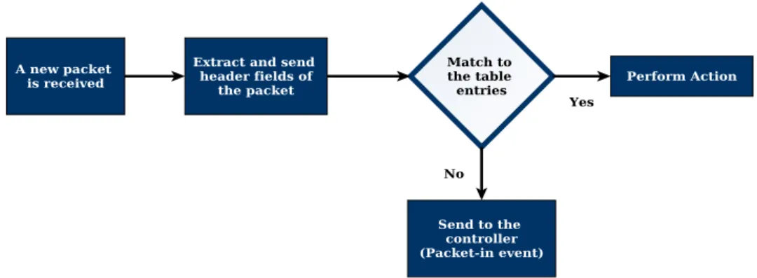
When an OpenFlow-enabled switch receives a new flow, it checks the packet headers with the existing forwarding rules in the flow table. If there is not any matching entry for the new flow, the switch generates a packet-in event and forwards the first packet of the received flow to the controller to decide about the actions for the flow. Consequently, the controller checks the packet-in and installs the rules on the switch for the received flow. From this point, the switch applies actions to the packets that match the rule in the flow table. Figure 2.3 demonstrates this process. This type of flow installation on the OpenFlow-enabled switches is called reactive flow installation. However, it is possible to implement proactive flow installation. In this case, the controller installs proper forwarding rules for possible flows on the switch before the switch receives a new flow. As a result, the switch forwards the packets according to the pre-installed rules [31].
2.2.3
OpenFlow Protocol
The OpenFlow protocol [2] uses different types of messages for interaction between the switches and the SDN controller. At the following, we explain in brief these messages and their functionalities.
Controller-to-Switch:
The controller sends the following messages to the switch. These messages may not need a reply from the switches.
• Features: The feature messages include the supported functionalities by the switches. The controller initiates these messages and the switch must respond to the request message from the controller.
• Configuration: The controller may set configurations on the switch with this type of message. Additionally, using these messages, it is possible for the controller to query the configurations of the switch.
• Modify-State: These messages are used by the controller to add, remove or modify the entries in the switch flow tables. It should be noted that this type of messages are known as flow-mod messages.
• Read-State: The controller sends these messages to query the statistics data for the flow entries, ports and flow tables of the switch.
• Send-Packet: The controller uses these messages to forward a packet out of a particular switch port. Also, this type of messages are known as packet-out messages.
• Barrier: The barrier messages might be used as a request/reply message to assure all sent messages have been received and all requested operations have been implemented correctly.
Asynchronous:
The switch initiates and sends these messages regardless of receiving any request from the controller.
• Packet-in: The packet-in messages are generated when a switch receives a new flow request and it cannot find any matching entry for the new flow. These packet-in messages are forwarded to the controller to decide about the new flow request. If the switch supports buffering and has enough memory for buffering, the packet-in includes a fraction of the packet (128 bytes by default) and a buffer ID. The buffer ID is used for forwarding the packet after receiving a response from the controller. In case the switch does not support buffering, the whole packet is forwarded to the controller.
• Flow-removed: The flows might be removed, for instance, because of timeouts. As a result, the flow-removed is used by the switch to inform the controller about the removed flows.
• Port-status: If the status of the switch port changes, the switch initiates this message and sends it to the controller.
• Error: In case of any problems, the switch sends error messages to the con-troller.
Symmetric:
These messages are transferred in both directions regardless of receiving any request from the controller or the switches.
• Hello: These messages are used at the starting point of the connection between the controller and the switch and they are transferred in both directions.
• Echo: Either the switch or the controller can send echo request messages to understand link properties like bandwidth and latency. The other side of the connection should respond to the request.
• Vendor: Vendor messages are used by vendors to provide additional features in OpenFlow messages.
2.2.4
Secure Channel
The secure channel is established between the controller and the switches at the data plane. SSL/TLS [25] is a secure protocol that has been proposed for the encryption of messages between the controller and the data plane. While the security of this channel is important, because of the configuration and technical issues, there is lack of interest in the implementation of TLS on this channel in today’s products [32]. It should be noted that the OpenDaylight controller supports TLS but it is not activated by default.
2.3
Chapter Summary
This chapter presents an overview of the SDN architecture. The SDN architec-ture consists of the application plane, the data plane, the controller plane and the management. The applications from the application plane interact with the SDN controller by using the northbound interface and the SDN controller controls the switches at the data plane using the southbound protocol. The OpenFlow protocol is the first southbound protocol that has been implemented in the SDN networks and it makes it possible to program the switches reactively or proactively by in-stalling forwarding rules. OpenFlow defines each forwarding rule with a set of fields including the match field, actions, counters, priority and timeouts.
Isolation in a Multi-Tenant SDN
Today’s networking trend is changing to offer more shared services. An example of recent technologies is the cloud computing which provides a possibility for different customers to share resources. The emergence of SDN takes this feature one step further by allowing the customers of a shared network to decide about their own traffic and route it in the network. While SDN effectively gives a higher level of functionality to the customers of a shared network, there should be a way to limit and restrict the customers to their own resources. In this chapter, we want to explore the possibility of multi-tenancy in SDN and digging into the existing isolation approaches in such environments. We start this chapter by explaining multi-tenancy in SDN network and then we focus on isolation approaches in a multi-tenant SDN. In the last section of this chapter, we discuss current multi-tenant solutions and their contributions to provide isolation in a multi-tenant SDN.
3.1
Multi-Tenancy in SDN
Multi-tenancy allows different customers to share the same infrastructure and re-sources and it provides the efficient way of maintenance and management. As a result, this model leads to a significant improvement in the hardware utilization and reduction in the operational costs. We define a tenant as a customer or organiza-tional entity which rents the resources of a SDN provider [35, 36, 59]. Based on our definition, in a multi-tenant SDN, tenants should be able to communicate with the controlling services offered by the SDN provider to control their own networks.
Tenants are able to connect to the SDN provider in different ways. At the fol-lowing, the possible configurations for a multi-tenant SDN are explained.
3.1.1
SDN Provider with Connected Tenant Applications
In this case, all SDN services and network resources are under control of a sin-gle provider which controls and configures the network elements in the data plane. The provider offers a possibility to tenants to connect to the SDN controller for configuring network resources. In this configuration, the provider may offer addi-tional features to the tenants or restrict the access of tenant applications to specific resources or services [3]. Figure 3.1 demonstrates this configuration.
Currently, the connection between tenant applications and the SDN controller is possible in two different ways: Northbound APIs [18] and Containers [38]. The northbound interface provides APIs for connecting applications to the controller. Most of the available SDN controllers support the northbound APIs for applications and it is part of the SDN architecture. Alternatively, it is possible to run the appli-cations using the containers. The container provides a space for an application to be running on the SDN controller. As a result, the controller system is shared between tenant applications. An example of these containers is Linux Containers (LXC). LXC is a lightweight virtualization mechanism that allows running multiple copies of Linux operating system on a single machine. The details of Linux containers are explained in [10].
Figure 3.1: SDN provider with application tenants
3.1.2
SDN Provider with Directly Connected Tenant
Con-trollers
In this configuration, the SDN provider allows different tenants to connect directly to the underlying network. The SDN provider configures and controls the network using the master controller and offers a virtual network to each of tenants. The virtual network is an abstract of the offered resources and ports of the network elements in the data plane. After assigning resources by the SDN provider, tenants can use their own controllers to connect directly to the network elements [3, 46, 47]. Figure 3.2 illustrates this configuration.
It should be noted that according to the SDN architecture [3], this configuration is not recommended since it exposes the underlying network and creates a vulnera-bility point in the network.
Figure 3.2: SDN provider with SDN tenants connected directly to the data plane
3.1.3
SDN Provider with Non-Recursively Connected
Ten-ant Controllers
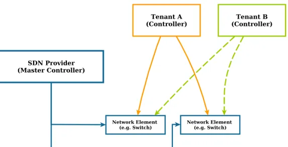
In this configuration, the SDN provider allows tenants to connect their own con-trollers to the network through another controller (or hypervisor). In fact, the SDN provider assigns network resources to tenants and tenants are able to access the resources through another controller provided by the SDN provider. According to Figure 3.3, the SDN provider offers an abstract of resources through the controller and tenants are connected to the SDN provider controller with their own controllers [3, 39, 49].
3.1.4
SDN Provider with Recursively Connected Tenant
Con-trollers
SDN provider is able to be placed in a recursive order with tenants. Figure 3.4 demonstrates this configuration. According to the figure, the SDN provider offers services to tenant B and tenant B offers services to tenant A. As a result, in this configuration, tenant A is using some of the offered services by the SDN provider but it is not directly connected to the SDN provider. The assigned services might be physical or virtual resources. For example, tenant B may offer physical resources which are tunneled to use the services from the SDN provider [3].
Figure 3.4: SDN Provider with Recursively Connected Tenant Controllers
3.2
Current Isolation Techniques in a Multi-Tenant
SDN
Isolation is one of the most important security aspects of multi-tenant environments. Since the resources are shared, it is vital to provide isolation between tenants. Iso-lation in a multi-tenant SDN can be achieved by implementing the isoIso-lation at the controller plane and the data plane. Tenants connect to the controller to send the configuration requests for forwarding at the data plane. Hence, there should be a possibility to differentiate these requests at the controller plane between all tenants. Moreover, at the data plane, we need to distinguish and forward the traffic of differ-ent tenants. At the following, we explain isolation techniques that have been used in current multi-tenant SDN solutions. It should be noted that different solutions
may use the combination of these approaches and they are not limited to only one technique. In Section 3.3, we explain some of the existing solutions that are using these techniques to provide isolation in a multi-tenant SDN network.
3.2.1
Slicing
In this approach, depending on the policy and the requirements of different tenants, we can slice a shared network [39, 40]. Consequently, each tenant is assigned a slice of network resources and it is limited to work on its own slice. A slice can be based on the 12-tuples of header fields discussed in Section 2.2.1. For example, slices can be based on source IP addresses. As a result, while the network resources are shared, based on the source IP addresses, the traffic of different tenants is distinguishable and all flows with a certain source IP address are placed in a specific slice. Additionally, it is possible to define slices based on the topology of the underlying network. This means a slice may consist of a set of switches, ports or links on the data plane. Consequently, all the traffic from those switches, ports or links belongs to a slice of a particular tenant. The slices are created by the administrator of the network who defines the slicing policy for all tenants.
3.2.2
Encapsulation
The encapsulation methods are used in a multi-tenant SDN network for traffic isola-tion at the data plane [38, 44]. By using the encapsulaisola-tion method in multi-tenant networks, the traffic of each tenant is tagged with a new header (label) at the ingress switch and it is removed at the egress switch. One of the well-known example of encapsulation methods is Virtual Local Area Network (VLAN) which allows to de-fine several virtual networks on a shared physical network. VLAN tagging based on IEEE 802.1q standard, adds a 12-bit tag to the frame. In a multi-tenant SDN, the controller tags the traffic of each tenant with a unique VLAN at the ingress switch and removes the tag at the egress switch. As a result, the usage of VLAN leads to traffic isolation at the data plane among tenants. While this approach is simple, it has the scalability problem and it is limited to 4096 number of VLANs [50].
Another example which is based on the encapsulation technique is Multiprotocol Label Switching (MPLS). The length of MPLS label is 20-bit which allows to define over a million labels [12, 26, 50]. The other way of encapsulation is the use of overlay network technologies like Virtual Extensible LAN (VXLAN). VXLAN allows the providers to define about 16 million virtual networks by adding 24-bit VXLAN Network Identifiers (VNIs) to frames [23].
3.2.3
Packet Rewriting
Packet rewriting at the controller plane
Considering a case where several tenants are connected to a shared controller plane. In this case, we need to isolate control requests (OpenFlow messages) between dif-ferent tenants. One way to isolate the requests that belong to difdif-ferent tenants is rewriting the control messages. In fact, for providing isolation between tenants,
the controller rewrites the control messages and delivers the requests to the corre-sponding tenant [39, 49]. Figure 3.5 illustrates a packet rewriting at the controller plane.
Figure 3.5: Packet rewriting at the controller plane
Packet rewriting at the data plane
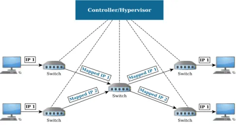
In this approach, the isolation is achieved by mapping the information in the packet header and rewriting the headers at the data plane [49]. In fact, for providing isolation, we change header fields to make packets distinguishable. In SDN networks, the controller is responsible to keep mapping between the original and the mapped information and usually, the packet rewriting is enforced at the edge of the network. For instance, it is possible to be implemented one type of mapping based on the source IP address. Consider the SDN network depicted in Figure 3.6. According to the figure, when one end-host sends traffic to the network with any IP address, the ingress switch, maps the host’s IP address to a predefined mapped IP address. When the traffic leaves the network at the egress switch, the mapped IP address will be changed to the original IP address. The IP address mapping in this example leads to the traffic isolation between different sources and makes it possible to choose overlapped IP addresses for end-hosts.
3.3
Available Multi-Tenant SDN Solutions and their
Isolation Approaches
In this section, we explain some of the available solutions that are used in a multi-tenant SDN network. These solutions provide multi-tenancy based on the config-urations explained in Section 3.1. For providing isolation, these solutions use the isolation approaches discussed in Section 3.2.
3.3.1
FlowN
FlowN [38] is a virtualization solution for multi-tenant SDN environments. It pro-vides the ability to define customized virtual networks for tenants. Tenants run their applications on the controller and the controller maps the traffic of each tenant from the virtual network at the controller plane to the physical network elements in the data plane. Figure 3.7 illustrates the architecture of this approach.
FlowN allows tenants to run their applications on LXC containers introduced in Section 3.1.1 and using these containers, the applications are able to communicate by function call and callback APIs with the controller system. The controller is responsible to assign an abstract view of the resources at the underlying network to the applications. It receives the requests from the tenant applications and translates them to the forwarding rules on the network elements in the data plane. Alterna-tively, the controller receives the requests from the data plane and forwards them to the tenant applications.
The isolation method at the data plane is based the encapsulation method in-troduced in Section 3.2.2. In fact, it assigns a VLAN tag for each tenant and these tags are appended to the traffic at the ingress switch and will be removed at the egress switch.
3.3.2
Splendid Isolation
Stephen Gutz et al.[44] introduced an isolation approach based on the slice abstrac-tion in SDN networks. The isolaabstrac-tion is achieved by making slices based on an abstraction of the underlying network resources and then, the defined slices and their corresponding programs are compiled with a compiler, which guarantees isola-tion between slices. The slices and programs are defined with NetCore [45], a high level language for OpenFlow-enabled networks.
The concept of slicing in this method is defined based on three factors: topology, mapping and predicates. The topology includes a set of switches and links that are used in a slice. The mapping defines the relation between the defined topology and the network elements in the data plane and the predicates are used to differentiate the traffic of different slices. It should be noted that the slices may be separated from each other (physical isolation) or they may have shared resources.
In this solution, tenants make programs according to their own topology. The compiler receives the slice definition and a program for that slice and compiles them together. The compiler chooses an unused VLAN tag for the slice and the associated program and it installs rules on the switch at the data plane to push and pop VLANs on packets that match the predicate of that slice. When a packet reaches an edge switch at the data plane, the predicates in the packet header are used to find a slice that the packet belongs to. After finding the slice, the traffic will be tagged with a VLAN tag. Later, this label is removed when the packet leaves the slice.
To verify the isolation between slices, a verification tool is developed. Instead of relying on compiler functionalities, the verification tool analyzes the output of the compiler. The isolation is verified in two aspects: Traffic isolation and Physical isolation. The traffic isolation ensures a packet that is forwarded in a slice is allowed to only traverse switches, ports and links for the corresponding slice. Moreover, the physical isolation is used in a case that one slice should not have any switch or links shared with other slices.
3.3.3
FlowVisor
FlowVisor [39, 40, 41, 42] creates a virtualization layer between the controller plane and the data plane in SDN networks. FlowVisor is placed between the tenants and network resources at the data plane and it allows to attach several controllers of different tenants to a shared network. FlowVisor allocates the resources of a shared network based on the slicing approach discussed in Section 3.2.1. It defines the concept of slice to divide the network resources between different tenants. A slice consists of a set of flows on the data plane which is named FlowSpace. To isolate the control traffic of different tenants, FlowVisor intercepts all OpenFlow messages and based on the slicing policy, it rewrites and forwards OpenFlow messages to the corresponding tenant controller. As a result, FlowVisor provides isolation and allows tenants to control their dedicated resources. Moreover, control traffic translation in FlowVisor leads to complete transparency for tenants and they do not notice the existence of this layer. Figure 3.8 demonstrates an example of the slicing approach based on the topology of the underlying network using FlowVisor.
Figure 3.8: Slicing approach (topology slicing) in FlowVisor
The isolation in FlowVisor can be classified into the following aspects:
• Bandwidth Isolation: FlowVisor provides bandwidth isolation based on the concept of the minimum bandwidth guarantee between slices. The minimum bandwidth for each slice is defined in slice’s policy. As a result, each slice can only consume a fraction of the bandwidth of the link based on the value specified in the definition of the policy for that slice. Consider an example where two slices are competing for the bandwidth on a shared link. FlowVisor may allow one slice to use only 30 percent of the bandwidth while the other slice may consume the 70 percent of the bandwidth of the link.
• Topology Isolation: To provide transparency, FlowVisor acts as a proxy and receives the connections from the switches at the data plane and forwards them to the related slices. Moreover, it receives OpenFlow messages that include information about switch ports and rewrites and forwards them to the corresponding tenant controller.
• Switch CPU Isolation: Switches with commodity hardware on the data plane are normally built based on low-power processors. Therefore, they can not process large amount of requests and they will be easily overloaded. To keep these devices responsive, there should be an isolation level between slices.
• FlowSpace Isolation: Slices should only affect the flows of their FlowS-paces. FlowVisor ensures isolation between slices by rewriting the OpenFlow messages to only affect the flows of the corresponding slice.
• Flow Entries Isolation: FlowVisor calculates the number of flow entries corresponding to each slice. If it surpasses the threshold, the error message “table full” is sent to the corresponding tenant controller.
• OpenFlow Control Isolation: The OpenFlow protocol uses a 32-bit trans-action identifier. FlowVisor rewrites this value for different controllers to pre-vent them from receiving an identical transaction identifier. Additionally, in case of packet-in events, the switch may keep the packet in an internal queue and send a request to the controller with a buffer id. A buffer id in Open-Flow messages should be changed for each slice. Furthermore, other OpenOpen-Flow messages like status messages need to be duplicated for all slices.
3.3.4
AutoSlice
AutoSlice [43, 48] is placed between the controller plane and the data plane and allows tenants to have an arbitrary virtual view of the underlying network. In this solution, tenants are able to connect their own controllers to AutoSlice and control their own virtual network. Figure 3.9 depicts the architecture of AutoSlice. The architecture of AutoSlice is based on two main components: Management Module (MM) and Controller Proxy (CPX). MM is used for receiving tenant network re-quests (virtual networks) and CPXs are used to manage the load from different tenant controllers. Furthermore, the underlying network is sliced into multiple SDN domains and each CPX is responsible to manage one SDN domain. When MM re-ceives a network request, it maps it to the resources on the underlying network and configures CPXs to process the tenant’s traffic for the corresponding SDN domain.
All control messages from the tenant’s controller are redirected to the CPX and it rewrites the control messages. Similar to FlowVisor, each CPX in AutoSlice checks the forwarding rules to be non-overlapped before installing on the switches. As a result, it guarantees the isolation between the flow entries of different tenants. To provide traffic isolation between different tenants at the data plane, AutoSlice embeds identifiers to packets. These identifiers are embedded in the packets with the encapsulation methods such as VLAN or MPLS. The encapsulation method is explained in Section 3.2.2.
3.3.5
OpenVirtex
OpenVirtex [49, 19] is the next generation of virtualization solutions. OpenVirtex is placed between the controller and the data plane and allows several tenants to con-nect to a shared network. Figure 3.10 shows the isolation approach at the controller plane and the data plane in OpenVirtex. Similar to FlowVisor, OpenVirtex rewrites the control messages (OpenFlow messages) for providing isolation between different tenant controllers. At the data plane, OpenVirtex rewrites the packet headers at the edge of the network and embeds the information about the virtual networks of each tenant in the packet headers. Since OpenVirtex rewrites the packet headers at the data plane, it provides traffic isolation and allows tenants to have overlapped IP addresses.
Figure 3.10: Isolation at the controller and data planes in OpenVirtex
3.4
Chapter Summary
This chapter discusses the multi-tenancy in SDN and particularly, the isolation in a multi-tenant SDN network. In a multi-tenant SDN, tenants are able to connect to the service provider network with their SDN controllers or applications and control their own network resources. Since, the network resources are shared, isolation be-comes a necessary requirement in a multi-tenant SDN. Current isolation techniques
for a multi-tenant SDN are slicing, encapsulation and packet rewriting. With slicing technique, the service provider slices network resources and assigns a slice to each tenant. The encapsulation method provides isolation by tagging the data packets and each tag (or label) in this method is assigned to one tenant. In the packet rewrit-ing approach, the packet headers are changed by the switches at the data plane to provide isolation between tenants. FlowN, FlowVisor and OpenVirtex are examples of current solutions which provide isolation by the aforementioned techniques.
Proposed System Design
In this chapter, we propose an architecture that provides isolation in a multi-tenant SDN network. In the proposed system, while a tenant is able to stay completely isolated from other tenants, it is possible to connect to the offered services by other tenants or allow others to use its own services. Moreover, since we are working in a multi-tenant network, the scalability is another challenge that we have considered in our solution. It should be applicable to deploy our isolation architecture in large networks with millions of tenants and hosts. At the following, at first, we present our design goals and then we start to explain about the principles that we have used in our architecture. These principles are the fundamental concepts that are used to explain the relation between tenants and provider network. Subsequently, we demonstrate a high level explanation of our solution. This includes a description on the functionality of the main components in our architecture. At the end of this chapter, we focus on the communication patterns and how tenants may interact with each other.
4.1
Design Goals
Our solution should fulfill the following requirements.
• Effective isolation in a multi-tenant network
Our system should provide complete isolation between tenants in a shared SDN network. We classify the isolation requirements into the following aspects:
Traffic isolation: The traffic of each tenant should completely be isolated from other tenants and there should not be any information leakage between tenants. Each tenant should be able to send any type of traffic to the network without affecting other tenants.
Address space isolation: In our solution, it should be possible to assign overlapped IP Addresses and MAC addresses to end-hosts of different tenants. In fact, while a tenant is working in its own subnet, it should not be possible to affect other tenants in the same address space in the network.
Control isolation: Tenants should be able to control their own traffic. There should be a possibility for tenants to connect to the network and define their
own policies for their traffic. Moreover, it should not be possible for a tenant to control others or affect the configurations made by other tenants.
Performance isolation: The performance isolation is a broad concept which can be defined in different perspectives. In our solution, we define performance isolation between tenants by setting a threshold on network resources for each tenant. As a result, tenants should not be able to violate the maximum allo-cated capacity of the network resources and all violations from tenants should be detected.
• Supporting intra-tenant, inter-tenant and external communications
It should be possible for tenants to make connection between their own hosts. Additionally, tenants may need to share specific services with each other within a shared network. While in existing solutions it is not simply feasible for a tenant to share services with other tenants, we aim to make a possibility for tenants to share and offer services to each other. Besides, tenants should be able to connect to the external services outside of a shared network (e.g. Internet).
• Satisfactory level of scalability
The solution should be scalable to be implemented in large networks with millions of hosts and tenants. Moreover, the scalability of the solution for deployment on today’s network devices should be taken into the consideration.
4.2
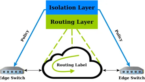
Design Pattern
Our solution separates the isolation layer from the routing layer. While the isolation layer guarantees that only verified flows are able to be transmitted, the routing layer decides about how to transmit a flow. The isolation layer matches the received flow requests with a set of rules and defines if the flow is allowed or not. The routing layer is concerned with the forwarding tasks at the data plane. It routes the verified flows in a specific path from the source to the destination.
Moreover, while the software switches can save millions of forwarding rules, to-day’s hardware switches cannot hold large number of forwarding rules in their flow tables [51, 52]. As a consequence, it is not possible to install fine-grained rules for each flow request in all switches available in the network. To tackle this issue, in our design we separate the edge from the core network. In fact, we isolate flow requests at the edges of the network and we route them at the core network based on the rout-ing labels. This approach is in accordance with the recent research efforts. Several of recent papers [51, 53] proposed to separate the edge and core networks by making edges more intelligent and providing label switching at the core. Our solution is similarly based on the same concept. While we enforce isolation at the edge of the network, we use routing labels to aggregate several flows together and route them at the core network. At the edge network, since we should implement fine-grained rules, we use software solutions and at the core network we use hardware switches to increase speed and efficiency for forwarding the flows. For enforcing isolation at the edge network, we use the concept of policy and isolation rules. Figure 4.1 illustrates the design of our solution.
Figure 4.1: Design pattern
4.3
Principles
In this section, we explain the concepts that are used in our architecture. For the rest of this thesis, we use these concepts to explain the functionality of our architecture.
4.3.1
SDN Provider
The SDN provider owns all network resources and it is responsible for all man-agement tasks in the infrastructure network. The SDN provider is responsible to implement the infrastructure network, configure the SDN controller and network elements (switches, gateway) in the data plane. Moreover, the SDN provider should register tenants to the network by creating an account and assigning network re-sources to each tenant.
4.3.2
Tenant
Referring to Section 3.1, we have defined a tenant as a customer or organizational entity which rents the resources of a SDN provider network. In our architecture, a tenant interacts with the SDN provider by connecting its application to the con-troller of the SDN provider. Tenants are able to create their own configurations, for instance, creating subnets for their hosts, creating policy group for their traffic and advertise their services to the other tenants.
4.3.3
Tenant Network Domain
Tenant Network Domain, which we will call it simply a domain, provides a way of managing network resources and creating boundaries between tenants [54]. In fact, a tenant is identified by its domain and all configurations related to a tenant are placed in its domain in the SDN provider network. At the controller plane, a domain
is uniquely identified by a domain label. These labels are generated randomly and they are unique between all domains in the network.
The SDN provider is responsible to create domains and assign each domain a set of input ports and a range of IP addresses. After the initialization process is done by the administrator, tenants are able to create, change or remove their own configurations in their domain.
4.3.4
Policy
Tenants create the policy for their traffic and services and this policy is mapped to the corresponding domain of a specific tenant. In our architecture, the definition of policy is based on policy groups. Each policy group has a set of accessibility levels. It can be defined as Intra-Tenant, Inter-Tenant and External. The intra-tenant means that the scope of this group is limited to one tenant. The inter-tenant group indicates that the scope of this group is between tenants in a shared SDN network. The external groups are used for communications with the resources outside of a shared network (e.g. Internet). A policy group may be defined to only have one accessibility level (for example Intra-tenant) or it can be defined to have more accessibility levels (for example Intra-tenant and Inter-tenant).
Additionally, every policy group consists of two main parts: isolation policy and routing policy.
Isolation Policy
The isolation policy includes a set ofrules. These rules are defined similar to firewall rules. The isolation policy is used for matching with the received flows. As a result, only a flow that matches a rule will be forwarded. Each rule includes source and destination IP addresses, source and destination transport port numbers and the protocol for the communication.
Routing Policy
The routing policy includes information that needs to be used for routing a flow at the underlying network. It includes information about routing decision and type of communication. By default, the routing decision is to drop all flows. However, the routing decision might be changed if the flow is allowed for forwarding based on the isolation policy. If the routing decision is changed to allow, then the flow is forwarded based on the type of communication.
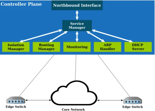
4.4
Architectural Components
In this section, we explain the main architectural components of our system. The northbound interface is used for making the configurations and interacting with the SDN controller. The Service Manager is responsible for processing the received configuration from the northbound interface. To respond to the received requests from the data plane five modules namedIsolation Manager,Routing Manager,ARP