Proceedings of the
Fourth International Workshop on
Graph-Based Tools
(GraBaTs 2010)
Visual Modeling of Controlled EMF Model Transformation
using H
ENSHINEnrico Biermann, Claudia Ermel, Johann Schmidt and Angeline Warning
13 pages
Guest Editors: Juan de Lara, Daniel Varro
Managing Editors: Tiziana Margaria, Julia Padberg, Gabriele Taentzer
Visual Modeling of Controlled EMF Model Transformation
using H
ENSHINEnrico Biermann, Claudia Ermel, Johann Schmidt and Angeline Warning
Institut f¨ur Softwaretechnik und Theoretische Informatik Technische Universit¨at Berlin, Germany
Abstract:The tool HENSHINis an Eclipse plug-in supporting visual modeling and execution of rule-based EMF model transformations. This paper describes the re-cent extensions of HENSHINby control structures for controlled rule applications. The control structures comprise well-known imperative structures like sequences and conditions on rule applications. Moreover, application conditions for individ-ual rules may now be arbitrarily nested and combined by logical connectors. We present the extension of the visual EMF model transformation environment HEN
-SHINto edit and perform controlled EMF model transformations along an example modeling a reactive Web service-based application (personal mobility manager).
Keywords:EMF, model transformation tool, graph transformation, Henshin
1
Introduction
Transformations are key modeling artefacts in model driven development. In graph transforma-tion approaches and tools, rules express basic transformatransforma-tion steps. The applicatransforma-tion of rules may be controlled implicitly like in AGG [AGG09], i.e. by a fixed strategy such as ”apply rules in arbitrary order as long as possible” and by providing negative application conditions for rules. Alternatively, control strategies may be defined explicitly like in Fujaba [FNTZ00], where an activity diagram (story diagram) defines loops or conditions on rule applications. Explicit con-trol structures raise the expressiveness of transformation systems since they provide means to regulate the transformation process without having to introduce helper structures into the rules.
In this paper, we lift implicit and explicit control structures from graph transformation to EMF model transformation and introduce an extension of our recently developed tool HENSHIN1by visual editors for control structures. HENSHINis an Eclipse plug-in supporting visual modeling and execution of EMF model transformations, i.e. transformations of models conforming to a meta-model given in the EMFEcoreformat2. The transformation approach we use in our tool is based on graph transformation concepts which are lifted to EMF model transformation by also taking containment relations in meta-models into account [ABJ+10].
Applying EMF model transformation rules in HENSHIN changes a modelin-place, i.e. the model is modified directly. Note that we speak ofEMF model transformationin a general sense,
1http://www.eclipse.org/modeling/emft/henshin/, originating from EMF TIGER[EMT09,BEK+06,BEL+10] 2Note that we use the termsmeta-modelandmodelin this paper, which are calledEMF modelandmodel instance
comprising not only source-to-target model-to-model transformations but also model refactor-ings or simulation of the system’s behavior3. The HENSHIN transformation engine provides classes that can freely be integrated into existing Java projects relying on EMF.
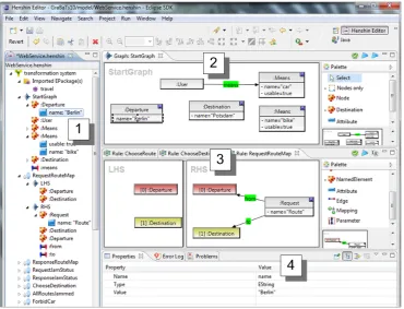
Figure 1 shows the basic GUI of our HENSHIN tool before the extensions presented in this paper. The tree view 1 allows the modeler to import EMF EPackagescontaining the basic meta-model(s) defining the domain of the transformation. The initial model is edited in a visual editor 2. In the rule editor 3, transformation rules can be created by editing a rule’s left-hand side (LHS, the pre-condition) and right-left-hand side (RHS, the post-condition). The rule in
Figure 1defines an operation which adds aRequestobject and links it to existingDeparture
and aDestinationobjects. The property view 4 shows additional information for selected objects. Note that all information edited using the editors in 2 , 3 and 4 can also be obtained via the tree view 1 .
Figure 1: HENSHINGUI with visual editors for graphs and rules.
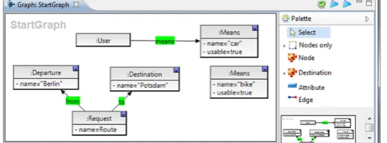
The rule shown in 3 can now be applied to the current model in 2 leading to the transformed graph shown in Figure 2, where a Request object has now been created and linked to the
Departure object named ”Berlin” and the Destination object named ”Potsdam”. The layout of newly added object is computed automatically but may be adjusted by the user.
Figure 2: Transformed graph after applying ruleRequestRouteMap
validation of consistent EMF model transformations which behave like algebraic graph transfor-mations [BET08], e.g. to show functional behavior and correctness.
In this paper we describe the recent extension of HENSHINsupporting the use of the control structures (called HENSHIN transformation units), e.g. constructs for non-deterministic rule choices, rule sequences or conditional rule applications. Those constructs may be nested to define more complex control structures. Passing of model elements as parameters from one unit to another is also possible. Apart from control units defined over sets of rules, we now also support the graphical definition of application conditions for individual rules. These are application conditions in the sense of [HP09] allowing for arbitrary nesting. Several application conditions can be combined by logical connectors.
The paper is structured as follows: inSection 2, the basic concepts of graph and EMF trans-formation are reviewed. Section 3presents our running example, the simulation of a personal mobility manager based on a web service. Modeling this example, we made extensive use of transformation units and application conditions which are introduced inSection 4andSection 5, respectively. Section 6 provides an overview of related approaches and tools in comparison to our tool, andSection 7concludes the paper with an outlook to future work.
2
EMF Model Transformation based on Graph Transformation
In this section, we introduce the main notions of modeling by algebraic graph transforma-tion [EEPT06] (Subsection 2.1) and relate these notions to EMF modeling terms (Subsection 2.2).
2.1 Typed Attributed Graphs and Graph Transformation
A domain-specific visual language (DSVL) is modeled by atype graph defining the underlying visual alphabet, i.e. the symbols (node types) and edge types which are available. Sentences or diagrams of the DSVL are given by graphs typed over (i.e. conforming to) the type graph. Node types may be attributed by attribute types.
consists of structure-preserving mappings from nodes inLHSto nodes inRHS, such that for an edge from noden1to noden2 inLHSwhich is preserved by the rule, we have a corresponding edge from noder(n1)tor(n2)inRHS. In our approach, all graph morphisms are injective, i.e.
they do not merge elements. Applying the rule(LHS−→r RHS)means to find a match ofLHS
in the source graph and to replace this matched part in the source graph by the corresponding
RHS, thus transforming the source graph into the target graph (this step is called adirect graph transformation). Intuitively, the application of rulerto graphGvia a matchmfromLHStoG
deletes the image m(LHS) fromG and replaces it by a copy of the right-hand sidem∗(RHS). Note that a rule may only be applied if the so-calledgluing conditionis satisfied, i.e. the deletion step must not leavedangling edges.
Definition 1(Graph Transformation) Let(LHS−→r RHS)be a typed graph transformation rule andGa typed graph with a typed graph morphismLHS−→m G, called match.
Adirect graph transformationG=r,⇒m HfromGto a typed graphH
via ruler, matchm, and co-matchm∗is shown in the diagram to the right. A sequenceG0⇒G1⇒..⇒Gnof direct graph
transforma-tions is calledgraph transformation, denoted asG0⇒∗ Gn.
LHS r //
m
RHS
m∗
G //H
A rule may be extended by input parameters, i.e. variables used to compute new attribute values for nodes in the right-hand side. When the rule is applied, the input parameters have to be bound to concrete values (either by the match or by user input).
2.2 Typed Attributed Graphs versus EMF Modeling
The Eclipse Modeling Framework EMF [EMF08] is a modeling and code generation facility for building tools and other applications based on a structured data model. Based on a meta-model, EMF provides tools and runtime support to produce a set of Java classes for the meta-model, a set of adapter classes that enable viewing and command-based editing of models conforming to the meta-model, and a basic (tree-based) editor. EMF provides the foundation for interoperability with other EMF-based tools, e.g. OCL checkers.
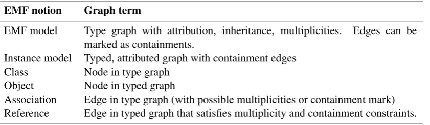
The conceptual similarities of modeling based on typed, attributed graphs and object-based modeling as performed by EMF are shown inTable 1.
Table 1: Mapping EMF notions to graph terminology
EMF notion Graph term
EMF model Type graph with attribution, inheritance, multiplicities. Edges can be marked as containments.
Instance model Typed, attributed graph with containment edges Class Node in type graph
Object Node in typed graph
Classes in an EMF model (i.e. the meta-model) correspond to nodes in a type graph. Asso-ciations between classes can be seen as edges in a type graph. Generalizations and multiplicity constraints of association ends can also be defined in the type graph. Objects as instantiations of classes of an EMF model are comparable to nodes in a graph which is typed by a type graph. Objects can be linked to each other by setting reference values. Such references correspond to edges in a typed attributed graph.
3
Example: Personal Mobility Manager
As running example, we specify and simulate the operational behavior of a Personal Mobility Manager (PMM), a reactive service-based application designed to satisfy requirements related to individual user mobility [LMEP08]. The aim of the system is to help the user finding an adequate route from a departure place to a destination and to propose an adequate means of transportation (either car or bike) by taking the current traffic intensity into account. We model the control flow of messages that are exchanged between the user, the PMM and corresponding Web service. To keep things simple, we do not model the actual web service here but simulate its responses by suitable variable assignments.
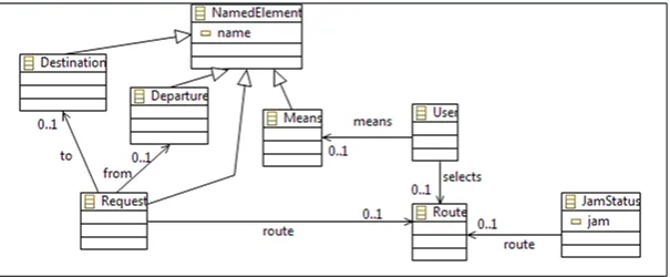
The modeling domain is specified as meta-model, shown inFigure 3. We have model elements for a user, his departure and destination locations, the means of transport, and requests sent to web service. ARouteelement contains a route given as response by the mobility web service, and aJamStatus element contains the response returned by the web service concerning the traffic on a given route.
Figure 3: Meta-model for the Personal Mobility Manager
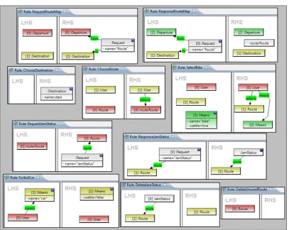
Figure 4: EMF model transformation rules for the Personal Mobility Manager
transport can be changed from the default means ”car” (as presented in the start graph inFigure 1) to the alternative means of transport ”bike”. This is realized by applying rulesForbidCarand
SelectBike. At last, the information about traffic (JamStatus node) and possible alter-native routes which have not been chosen, are deleted using rules DeleteJamStatus and
DeleteUnusedRoute.
In the next section, we explain the use of HENSHIN transformation units to encapsulate and control the order of rule applications.
4
H
ENSHINTransformation Units
true) if it can be successfully executed. PriorityUnits andIndependentUnits are always appli-cable, whileSequentialUnits(CountedUnits) are applicable only if all subunits are applicable in the given order (the given number of times). AConditionalUnit is applicable if either thethen -subunit (in case the condition istrue) or theelse-subunit (in case the condition isfalse) are applicable.
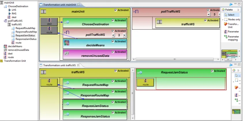
HENSHIN transformation units may be defined in the tree view or, alternatively, in a visual editor. The tree view shows all transformation units and their nesting hierarchy (seeFigure 5). The visual editor for one unit shows the unit in a left view and one selected subunit in a right view. Unit and subunit may share parameters indicated by the coloring of the parameter fields (seeFigure 5, where editors for unitmainUnitand unittrafficWSare opened in parallel). A transformation unit view shows the unit’s name as header, a checkboxActivated which the user may select/deselect to indicate whether this unit is active (will be considered while executing), a set of parameters shown as boxes in the left column, and the names and kinds of its subunits in the right column. Arrows from (to) parameter boxes to (from) subunits indicate which parameters are input (output) of which subunit.
Figure 5: HENSHINGUI with transformation unit editor
The transformation unitmainUnitshown inFigure 5 is the main control structure for the PMM example. It is aSequentialUnit(symbolized by a film strip as icon in the upper left corner) containing four subunits. This means that each subunit is applied once, in the given order from top to bottom. The first subunit, ChooseDestinationis a transformation rule, marked by gear-wheels (see Figure 4for the rule definition). This rule has an input parameter, the desti-nationdest, a user-defined parameter. The second subunit of the main unit is aCountedUnit (symbolized by a ”×n” icon). The counter is set to 3, i.e. its subunit is applied three times. Unit
the lower left view: ruleResponseRouteMapproduces an output parameter of typeRoute
which serves again as input parameter for ruleRequestJamStatus.
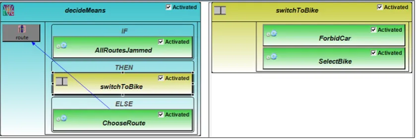
The third subunit ofmainUnit,decideMeans, is aConditionalUnit(symbolized by an if-then-elseicon). Clicking on its field, a detailed view of this unit is opened (seeFigure 6). Here, a condition calledAllRoutesJammed(which will be discussed inSection 5) is checked which is given as an empty rule where we check its application condition. If the condition is evaluated totrue, the two rulesForbidCarandSelectBikein the sequential unit are applied in this order. Otherwise, ruleChooseRouteis applied and the parameterrouteis returned to the parent unitmainUnit.
Figure 6: HENSHINtransformation unitdecideMeans
The last child unit ofmainUnitis theIndependentUnit removeUnusedData(with a die as icon symbol). This unit contains two rules, DeleteJamStatus and DeleteUnused-Routewhich perform garbage collection and are applied in arbitrary order, as long as possible.
5
Application Conditions
For graph transformation rules, well-known negative application conditions may be used that forbid to apply a rule if a certain structure is present in the graph. As a generalization, appli-cation conditions (introduced as nested application conditions in [HP09]) further enhance the expressiveness of graph transformations by providing a more powerful mechanism to control rule applications. While application conditions are as powerful as first order logic on graphs, we can still obtain most of the interesting results available for graph transformationswithout ap-plication conditions also for transformationswithapplication conditions [EHL+10a,EHL10b] if certain additional properties hold.
Like transformation units, application conditions can be nested. Moreover, application condi-tions may be negated, and several application condicondi-tions may be combined by using the logical connectors AND and OR.
Definition 2(Graph condition and application condition) Agraph condition acover graphG
a conclusion graphC, andcis a condition overC. Moreover, Boolean formulas over conditions overPyield conditions overP, i.e. ¬cand∧j∈Jcj are (Boolean) conditions over PwhereJ is
an index set andc,(cj)j∈Jare conditions overP. Additionally,∃aabbreviates∃(a,true),∀(a,c)
abbreviates ¬∃(a,¬c), false abbreviates ¬true, ∨j∈Jcj abbreviates ¬ ∧j∈J¬cj, and c =⇒ d
abbreviates¬c∨d. A graph conditionacis calledapplication conditionof ruler:L→Rifac
is a graph condition overL; an application condition of the form¬∃ais usually callednegative application condition.
A condition is satisfied by a morphism into a graph if the required structure exists, which can be verified by the existence of suitable morphisms.
Definition 3(Satisfaction of conditions) Given a graph conditionac, a morphism p:P→G
satisfiesac, writtenp|=ac, ifac=true. A morphismp:P→Gsatisfies conditionac=∃(a,c) if there is an injective graph morphismq:C→G such that q◦a= p and q satisfiesc. The satisfaction of conditions by graphs and morphisms is extended to Boolean conditions in the usual way. A rule L→R is applicable only if the application conditionac is satisfied for its matchm:L→G, i.e. ifm|=ac.
Let us consider once more theConditionalUnit decideMeansfrom our PMM example (see
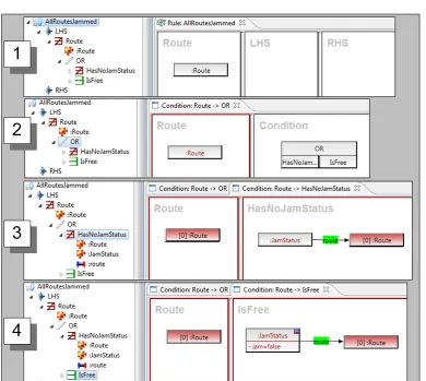
Figure 6). Here, the condition AllRoutesJammed is expressed by an empty rule4 with a nested application condition, shown inFigure 7.
In view 1 ofFigure 7, the empty rule is shown together with the outermost condition graph (condition over LHS). In the tree view of 1, it can be seen that we require ¬∃Route, i.e. a morphism from graph Route (consisting of a single Route node) into the host graph must not exist for the rule to be applicable. Since this application condition is nested, we require a further condition for theRoutegraph, formulated as disjunction (OR-construct) over two more conditions:(¬∃HasNoJamStatus∨ ∃IsFree). This formula can be seen in the tree view of 2, as well as in the corresponding visual hierarchical view where the formula is depicted as an OR block with two compartments. Clicking on one of the two parts of the disjunction in the visual view (or on one of the two OR branches in the tree view) opens the next level, either for the formula¬∃HasNoJamStatusin 3 or for the formula∃IsFreein 4. Here, we have arrived at the basic level of graph morphisms. The complete nested application condition means that the empty rule is applicable (returns true) if there exists no route that has either noJamStatus
node or that has aJamStatusnode with attribute jam=false. Recall that in this case (all routes are jammed) unitdecideMeans(seeFigure 6) applies ruleswitchToBike, otherwise a route is chosen for the car as transport means.
6
Related Work
There are a number of model transformation engines which can modify models in EMF format such as ATL [JK05], EWL [KPPR07], Tefkat [LS05], VIATRA2 [VB07], MOMENT [Bor07]. 4Note that we allow arbitrary transformation units as conditions inConditionalUnits. While this may lead to side
effects if a unit different from the empty rule is used, the conceptual advantage is that components of HENSHIN
Figure 7: Empty ruleAllRoutesJammedwith application condition
For ATL, a formal semantics based on Maude has been introduced recently [TV10]. Formal semantics defined in Maude for MOMENT and for ATL might be exploited for analyzing EMF model transformations. None of these tool environments supports visual editing of control struc-tures.
(based on graph transformation or not) support confluence and termination analysis of EMF model transformation rules yet. Here, the HENSHIN approach and tool environment serves as a bridge to make well-established tool features and formal techniques for graph transformation available for model-driven development based on EMF.
7
Conclusion
In this paper, we presented two extensions for supporting controlled EMF transformations in our EMF transformation environment HENSHIN. The first extension supports the visual definition of HENSHINtransformation units which may be hierarchically nested (the basic unit being a rule)
and which restrict the possible rule application sequences in a suitable way. The second exten-sion concerns the definition of application conditions for transformation rules. Such conditions may be nested as well, and they may be combined by logical connectors such asANDandOR. We illustrated the usage of the extended HENSHIN environment by a simulation example of a personal mobility manager (PMM). Apart from the PMM example, HENSHINhas been applied also for larger case studies, e.g. for model refactorings [ABJ+10] and model-to-model transfor-mations such as theEcore2Genmodelcase study of the Transformation Tool Contest 2010 [?]5. The extended HENSHINenvironment provides visual views for all control structures and con-ditions supporting zooming into deeper nesting levels. Thus, the visualization is independent of the complexity of the (nested) control structures, as only two levels are shown at a time. Both tree view editing and visual editing is supported at all levels. For editing formulas within appli-cation conditions, from the user’s perspective an additional textual view of a complete formula might be desirable [GP96]. The integration of such a textual formula view in HENSHINis work in progress.
A special kind of transformation units in HENSHINareAmalgamationUnits, which are useful to specifyforall-operations on recurring model patterns. AnAmalgamationUnit is a multi-rule scheme containing the model pattern and a fixed kernel rule part. An amalgamated rule, induced by such a scheme, is a kind of parallel rule synchronized at the kernel rule part. Its application modifies all recurring instances of the model pattern in one step. The development of a visual editor within HENSHINforAmalgamationUnitsis work in progress.
Furthermore, on the theoretical side we aim to lift confluence and termination analysis results from the rule level to the level of transformation units.
References
[ABJ+10] T. Arendt, E. Biermann, S. Jurack, C. Krause, G. Taentzer. Henshin: Advanced Concepts and Tools for In-Place EMF Model Transformations. In Proc. of the ACM/IEEE 13th Intern. Conf. on Model Driven Engineering Languages and Sys-tems (MoDELS’10). LNCS 6394, pp. 121–135. 2010.
http://tfs.cs.tu-berlin.de/publikationen/Papers10/ABJ+10.pdf
[AGG09] TFS-Group, TU Berlin. AGG. 2009.http://tfs.cs.tu-berlin.de/agg. 5On the TTC webpagehttp://planet-research20.org/ttc2010/a Share demo of H
[BEK+06] E. Biermann, K. Ehrig, C. K¨ohler, G. Kuhns, G. Taentzer, E. Weiss. Graphical Def-inition of In-Place Transformations in the Eclipse Modeling Framework. In Nier-strasz et al. (eds.),Proc. of the International Conference on Model Driven Engineer-ing Languages and Systems (MoDELS’06). LNCS 4199, pp. 425–439. Springer, Berlin, 2006.
http://tfs.cs.tu-berlin.de/publikationen/Papers06/BEK+06a.pdf
[BEL+10] E. Biermann, C. Ermel, L. Lambers, U. Prange, G. Taentzer. Introduction to AGG and EMF Tiger by Modeling a Conference Scheduling System.Int. Journal on Soft-ware Tools for Technology Transfer12(3-4):245–261, Juli 2010.
http://www.springerlink.com/content/p4n1g45627852743/
[BET08] E. Biermann, C. Ermel, G. Taentzer. Precise Semantics of EMF Model Transfor-mations by Graph Transformation. In Czarnecki (ed.),Proc. ACM/IEEE 11th Inter-national Conference on Model Driven Engineering Languages and Systems (MoD-ELS’08). LNCS 5301, pp. 53–67. Springer, 2008.
http://tfs.cs.tu-berlin.de/publikationen/Papers08/BET08.pdf
[Bor07] A. Boronat.MOMENT: A Formal Framework for Model Management. PhD thesis, Universitat Polit`ecnica de Val`encia, 2007.
[EEPT06] H. Ehrig, K. Ehrig, U. Prange, G. Taentzer. Fundamentals of Algebraic Graph Transformation. EATCS Monographs in Theor. Comp. Science. Springer, 2006.
http://www.springer.com/3-540-31187-4
[EHL+10a] H. Ehrig, A. Habel, L. Lambers, F. Orejas, U. Golas. Local Confluence for Rules with Nested Application Conditions. In Ehrig et al. (eds.), Proceedings of Intern. Conf. on Graph Transformation (ICGT’ 10). LNCS 6372, pp. 330–345. Springer, 2010.
http://tfs.cs.tu-berlin.de/publikationen/Papers10/EHL+10.pdf
[EHL10b] H. Ehrig, A. Habel, L. Lambers. Parallelism and Concurrency Theorems for Rules with Nested Application Conditions.Electr. Communications of the EASST 26:1– 24, 2010.
http://journal.ub.tu-berlin.de/index.php/eceasst/issue/view/36
[EMF08] Eclipse Consortium. Eclipse Modeling Framework (EMF) – Version 2.4. 2008.
http://www.eclipse.org/emf.
[EMT09] TFS-Group, TU Berlin. EMF Tiger. 2009.http://tfs.cs.tu-berlin.de/emftrans. [FNTZ00] T. Fischer, J. Niere, L. Torunski, A. Z¨undorf. Story Diagrams: A new Graph Rewrite
Language based on the Unified Modeling Language. In Engels and Rozenberg (eds.),Proc. of the6thInternational Workshop on Theory and Application of Graph Transformation (TAGT). LNCS 1764, pp. 296–309. Springer, Berlin, 2000.
[GK08] R. Geiß, M. Kroll. GrGen.NET: A Fast, Expressive, and General Purpose Graph Rewrite Tool. In Sch¨urr et al. (eds.), Proc. 3rd Intl. Workshop on Applications of Graph Transformation with Industrial Relevance (AGTIVE’07). LNCS 5088. Springer, 2008.
[GP96] T. R. G. Green, M. Petre. Usability Analysis of Visual Programming Environments: a ‘cognitive dimensions' framework.Journal of Visual Languages and Com-puting7(2):131–174, 1996.
[HP09] A. Habel, K.-H. Pennemann. Correctness of high-level transformation systems rel-ative to nested conditions.Mathematical Structures in Computer Science19:1–52, 2009.
[JK05] F. Jouault, I. Kurtev. Transforming Models with ATL. InMoDELS Satellite Events. LNCS 3844, pp. 128–138. Springer, Berlin, 2005.
[KPPR07] D. Kolovos, R. Paige, F. Polack, L. Rose. Update Transformations in the Small with Epsilon Wizard Language.Journal of Object Technology6(9):53–69, 2007.
[LMEP08] L. Lambers, L. Mariani, H. Ehrig, M. Pezze. A Formal Framework for Developing Adaptable Service-Based Applications. In Fiadeiro and Inverardi (eds.),Proc. Fun-damental Approaches to Software Engineering (FASE’08). LNCS 4961, pp. 392– 406. Springer, 2008.
[LS05] M. Lawley, J. Steel. Practical Declarative Model Transformation with Tefkat. In
MoDELS Satellite Events. LNCS 3844, pp. 139–150. Springer, Berlin, 2005.
[MV08] B. Meyers, P. Van Gorp. Towards a Hybrid Transformation Language: Implicit and Explicit Rule Scheduling in Story Diagrams. InProceedings of the 6th International Fujaba Days. 2008.
[SWZ99] A. Sch¨urr, A. Winter, A. Z¨undorf. The PROGRES-Approach: Language and Envi-ronment. In Ehrig et al. (eds.),Handbook of Graph Grammars and Computing by Graph Transformation, Volume 2: Applications, Languages and Tools. Pp. 487 – 550. World Scientific, River Edge, NJ, USA, 1999.
[TV10] J. Troya, A. Vallecillo. Towards a Rewriting Logic Semantics for ATL. In Tratt and Gogolla (eds.),Proc. of the Intern. Conf. on Model Transformation (ICMT’10). LNCS 6142, pp. 230–244. Springer, 2010.