Audiometer Calibration
System Manual
IAUDIT.01 Rev J
Larson Davis
Audiometer Calibration System
Manual
Copyright
Copyright 2015 by PCB Piezotronics, Inc. This manual is copyrighted, with all rights reserved. The manual may not be copied in whole or in part for any use without prior written consent of PCB Piezotronics, Inc.
Trademarks
PCB is a registered trademark of PCB Piezotronics, Inc. LEMO is a registered trademark of LEMO SA. LEMO USA is a registered trademark of INTERLEMO HOLDING USA. Microsoft Access and Microsoft Excel are either registered trademarks or trademarks of Microsoft Corporation in the United States and/or other countries. B&KBK, and Bruel & Kjaer are registered trademarks of Bruel & Kjaer Sound & Vibration Measurement A/S.
Disclaimer
The following paragraph does not apply in any state or country where such statements are not agreeable with local law:
Even though PCB Piezotronics, Inc. has reviewed its documentation, PCB Piezotronics, Inc. makes no warranty or representation, either expressed or implied, with respect to this instrument and documentation, its quality, performance, merchantability, or fitness for a particular purpose. This documentation is subject to change without notice, and should not be construed as a commitment or representation by PCB Piezotronics, Inc.
This publication may contain inaccuracies or typographical errors. PCB Piezotronics, Inc. will periodically update the material for inclusion in new editions. Changes and improvements to the information described in this manual may be made at any time.
Recycling
PCB Piezotronics, Inc. is an environmentally friendly organization and encourages our customers to be environmentally conscious. When this product reaches its end of life, please recycle the product through a local recycling center or return the product to:
PCB Piezotronics, Inc. Attn: Recycling Coordinator 1681 West 820 North
IAUDIT.01 Rev I
Table of Contents
Chapter 1
Welcome to AUDit Audiometer Intelligent Testing
1-1
Formatting Conventions ... 1-2 Unpacking and Inspection ... 1-2 Software Installation ... 1-7 Starting the Software ... 1-8
Chapter 2
Initial Configuration
2-1
Creating a Database ... 2-1 Entering Instrumentation ... 2-3 Preferences ... 2-13
Chapter 3
Audiometer Test Setup
3-1
Equipment ... 3-3 Microphones ... 3-4 Audiometer ... 3-7 Earphones Screen ... 3-8
Chapter 4
Booth Test or Ambient Noise Level Test
4-1
Equipment for Booth Test ... 4-2 Assembling the system ... 4-3 Connecting the SLM ... 4-5 System Acoustic Calibration ... 4-6 Performing a Booth Test ... 4-8 Saving a Booth Test ... 4-10 Suspecting Instrument Noise ... 4-11
Chapter 5
Audiometer Test System Assembly
5-1
Audiometer Transducer Test Configurations ... 5-2 Connect the PC, 824 and PRM902 Preamplifier ... 5-2 AEC100 Coupler Assembly and Calibration ... 5-4 AEC201 Ear Simulator and Assembly and Calibration ... 5-12 AMC493B Assembly for Testing Bone Vibrators ... 5-21
Chapter 6
Hearing Level Test
6-1
Calibration Main Measurement Screen ... 6-1 Frequency Test with Earphone Transducers ... 6-2
Chapter 7
Frequency Test
7-1
Calibration Main Measurement Screen ... 7-1 Frequency Test with Earphone Transducers ... 7-2
Chapter 8
Linearity Test
8-1
Linearity Measurement Screen ... 8-1
Chapter 9
Distortion Test
9-1
Harmonic Distortion Measurement Screen ... 9-2
Chapter 10
Pulse Test
10-1
Pulse Measurement Screen ... 10-2
Chapter 11
Cross Talk Test
11-1
Chapter 12
Frequency Modulation Test
12-1
Chapter 13
Narrow Band Level Test
13-1
Narrow Band Level Test with Earphone Transducers ... 13-2 Narrow Band Level Test with Speakers ... 13-5
Chapter 14
Broad Band Noise Masking Test
14-1
Broad Band Masking Measurement Screen ... 14-1
Chapter 15
Speech Test
15-1
Speech Measurement Screen ... 15-1 Speech Test with Earphone Transducers ... 15-2 Mic Test ... 15-3 Tape/CD A and Tape/CD B Test ... 15-4 Speech Test with Bone Vibrator ... 15-6 Speech Test with Speakers ... 15-7
AUDit Manual Welcome to AUDit Audiometer Intelligent Testing 1-1
C H A P T E R
1
Welcome to AUDit
Audiometer Intelligent Testing
The Larson Davis audiometer calibration system has been designed for simplicity, portability, and durability. System weight, volume and component count have been carefully managed. Measurements for this system are made using the Larson Davis Model 824 precision sound level meter, which enables the user to perform complete Audiometer Calibrations per the requirements of ANSI S3.6-2004 and IEC 60645-2001 as well as testing Maximum Permissible Ambient Noise Levels for Audiometric Test Rooms per ANSI S3.1-1999(R2008).This system offers the following features:
• A whole range of transducers, their corrections and limits have been implemented, including: circumaural, supra-aural, insert earphones, bone vibrators, and speakers. • A measurement database search allows quick reference
to previously calibrated audiometers to speed up test configuration or compare the current test with historical data
• Extended frequencies can be tested using appropriate couplers such as the Larson Davis AEC201 coupler and plates.
Formatting Conventions
This manual uses the following format conventions:
• In step-by-step directions, the process (what you do) is shown in the right column, and the rationale (why you do it) with other cautions and comments are shown in the left column.
• User Input: this bold sans-serif typeface indicates values or selections entered in the software.
• Screen prompts: this bold italic typeface denotes menu items, prompts, messages, and other textual information reported by the software.
Unpacking and Inspection
If you have received this manual as part of a complete Larson Davis audiometer calibration system, this section will acquaint you with its components. Your order has been shipped in protective packaging. As most audiometer calibration hardware must be recertified on an annual basis, please try to save these packing materials for future use.
Important: If your packaging was
damaged in transit, please contact your shipping provider for instruc-tions on filing a claim.
Please compare your system with the following table and note any discrepancies before contacting your Larson Davis representative.
AUDit Manual Unpacking and Inspection 1-3
SYS008
This system has the same components as the SYS009 with the exception of the AMC493B artificial mastoid.
Part Description
2575 1 inch precision pressure response microphone, and case 824 Precision integrating sound level meter including
PRM902 1/2 inch preamplifier with 7 pin LEMOconnector PSA027 90-264 Volt to 12 V Power supply.
BAT010 nickel metal hydride AA rechargeable battery pack CBL006 serial communications cable (with 9 pin D connector) CBL042 stereo phone plug to dual BNC output cable I824.01 operator manual
I824.02 training manual
I824.03 firmware upgrade instruction sheet SWW 824 utility software CD
WS001 - 3 1/2 inch foam windscreen
AM814.06 Neg/Pos AA term Spring Assy for individual AA battery cell use 824-AUD Audiometric test (internal 824 firmware option)
ADP006 BNC to 1/2 inch preamp thread adaptor with equivalent 47 pF capacitance for direct input to 824
ADP008 1/2 inch preamp to 1 inch microphone thread adaptor ADP010 Audiometer earphone adaptor for electrical input to 824
AEC100 6cc coupler (NBS-9-A coupler) with base, coupler, retaining ring, microphone cap, mass and handle (weight), and pillow
ADP019 1/2 inch MIC TO 1 inch CAL adaptor
CAL250 Precision microphone calibrator with 1 inch opening I250.1 CAL250 operation manual
CCS007 Weather-tight hard carrying case DVX011 USB to serial adaptor
EXA010 10 foot microphone extension cable SWW-AUDIT Audiometer calibration software including
SYS009 with AMC493B
Part Description
2575 1 inch precision pressure response microphone, and case 824 Precision integrating sound level meter including
PRM902 1/2 inch preamplifier with 7 pin LEMO connector PSA027 90-264 Volt to 12 V Power supply.
BAT010 nickel metal hydride AA rechargeable battery pack CBL006 serial communications cable (with 9 pin D connector) CBL042 stereo phone plug to dual BNC output cable I824.01 operator manual
I824.02 training manual
I824.03 firmware upgrade instruction sheet SWW-824.F utility software CD
WS001 - 3 1/2 inch foam windscreen
AM814.06 Neg/Pos AA term Spring Assy for individual AA battery cell use 824-AUD Audiometric test (internal) 824 firmware option
ADP006 BNC to 1/2 inch preamp thread adaptor with equivalent 47 pF capacitance for direct input to 824
ADP008 1/2 inch preamp to 1 inch microphone thread adaptor ADP010 audiometer earphone adaptor for electrical input to 824
AEC100 ’6cc coupler’ (NBS-9-A coupler) with base, coupler, retaining ring, micro-phone cap, mass and handle (weight), and pillow
ADP019 1/2 inch MIC TO 1 inch CAL adaptor AMC493B Artificial mastoid coupler and case
IAMC493B.01 AMC493B operator manual MAE100.55 additional weight ring
CAL250 Precision microphone calibrator with 1 inch opening I250.1 CAL250 operator manual
CCS007 Weather-tight hard carrying case DVX011 USB to serial adaptor
EXA010 10 foot microphone extension cable SWW-AUDIT Audiometer calibration software including
AUDit Manual Unpacking and Inspection 1-5
SYS010 with AEC201-A
Part Description
824 Precision integrating sound level meter including
PRM902 1/2 inch preamplifier with 7 pin LEMO connector PSA027 90-264 Volt to 12 V Power supply.
BAT010 nickel metal hydride AA rechargeable battery pack CBL006 serial communications cable (with 9 pin D connector) CBL042 stereo phone plug to dual BNC output cable I824.01 operator manual
I824.02 training manual
I824.03 firmware upgrade instruction sheet SWW-824.F utility software CD
WS001 - 3 1/2 inch foam windscreen
AM814.06 Neg/Pos AA term Spring Assy for individual AA battery cell use 824-AUD Audiometric test (internal) 824 firmware option
ADP006 BNC to 1/2 inch preamp thread adaptor with equivalent 47 pF capacitance for direct input to 824
ADP008 1/2 inch preamp to 1 inch microphone thread adaptor ADP010 audiometer earphone adaptor for electrical input to 824 ADP019 1/2 inch MIC TO 1 inch CAL adaptor
AEC201-A IEC 60318-1:2009 Ear Simulator with 377A13 microphone CAL250 Precision microphone calibrator with 1 inch opening
I250.1 CAL250 operator manual CCS007 Weather-tight hard carrying case DVX011 USB to serial adaptor
EXA010 10 foot microphone extension cable SWW-AUDIT Audiometer calibration software including
SYS011 with AMC493B and AEC201-A
Part Description
824 Precision integrating sound level meter including
PRM902 1/2 inch preamplifier with 7 pin LEMO connector PSA027 90-264 Volt to 12 V Power supply.
BAT010 nickel metal hydride AA rechargeable battery pack CBL006 serial communications cable (with 9 pin D connector) CBL042 stereo phone plug to dual BNC output cable I824.01 operator manual
I824.02 training manual
I824.03 firmware upgrade instruction sheet SWW-824.F utility software CD
WS001 - 3 1/2 inch foam windscreen
AM814.06 Neg/Pos AA term Spring Assy for individual AA battery cell use 824-AUD Audiometric test (internal) 824 firmware option
ADP006 BNC to 1/2 inch preamp thread adaptor with equivalent 47 pF capacitance for direct input to 824
ADP008 1/2 inch preamp to 1 inch microphone thread adaptor ADP010 audiometer earphone adaptor for electrical input to 824 ADP019 1/2 inch MIC TO 1 inch CAL adaptor
AEC201-A IEC 60318-1:2009 Ear Simulator with 377A13 microphone AMC493B Artificial mastoid coupler and case
IAMC493B.01 AMC493B operator manual MAE100.55 additional weight ring
CAL250 Precision microphone calibrator with 1 inch opening I250.1 CAL250 operator manual
CCS007 Weather-tight hard carrying case DVX011 USB to serial adaptor
EXA010 10 foot microphone extension cable SWW-AUDIT Audiometer calibration software including
AUDit Manual Software Installation 1-7
Software Installation
Hardware and Software Requirements
The following table lists the requirements for the installation and use of the AUDit software for audiometer calibration. • Operating system: Windows XPTM SP3 (32-bit),
Windows Vista ProfessionalTM SP1 (32-bit), Windows
7TM (32-bit and 64-bit), and Windows 8TM (32-bit and
64-bit). AUDit software must be installed using Administrator rights.
• Network: AUDitTM
is not designed to work on a distributed network from a network drive. However, it may be operated from a local installation on a computer connected to a network.
• Communications: One available 9-pin serial communication port, 9600 baud or greater recommended or DVX011, USB Adapter to DBM9 interface (824) to USB port on PC.
Installing the Software
Place the AUDit CD in your PC and follow the onscreen instructions. You can accept the default settings on each screen for proper installation.
FIGURE 1-1 AUDit Icon on desktop
Look for new icon on the PC Desktop.
Getting Help
Contact PCB Piezotronics Technical Support at 888-258-3222 (toll free) or +1 716 926-8243 if you encounter any problems with the installation or use of AUDit software.
Starting the Software
Step 1 On the PC desktop, double click the AUDit icon to run the software. If this is the first time you have used the AUDit software, you will be asked if you wish to create a new database.
FIGURE 1-2 Create new database Dialog Box
Step 2 Selecting Yes will create a database named
Auditdb.mdb in the default directory. To create a database later in another directory select No.
FIGURE 1-3 Could not open database Dialog Window
Step 3 You will be able to enter a database name and directory in the File, Change Database... menu
AUDit Manual Initial Configuration 2-1
C H A P T E R
2
Initial Configuration
Before performing a measurement, a few items need to be configured in the AUDit software. This chapter covers setting up a database, configuring the system printer, entering calibration instrumentation information and other user preferences.
Creating a Database
The measurement database is a Microsoft Access compatible file which contains information about calibration instruments, as well as audiometer and booth test results. During installation, you may have elected to create a blank database (by default Auditdb.mdb in the current directory). If so, you may skip this section.
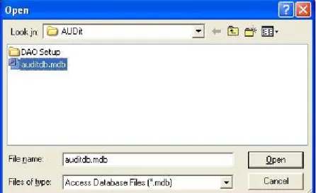
To create a new database, click File, Change Database... in the AUDit menu to open the Change Database dialog box then click Browse.
The Open dialog box will appear, allowing you to select a database. To create a database enter a new database name and select open.
AUDit Manual Entering Instrumentation 2-3
Entering Instrumentation
NOTE:When the desired instrumenta-tion is selected for use with an audiome-ter measurement, a copy is stored with the measurement. If changes are later made to the instrumentation, those changes will not be reflected in the copy that is stored with the measurement.
The AUDit audiometer calibration software maintains a list of the instruments used for calibration. These are normally certified traceable to NIST (National Institute of Standards and Technology) measurement standards at specified intervals. All this information is entered in the Instrumentation... Screen, shown in FIGURE 2-4.
Click Test, Instrumentation to display the Instrumentation screen.
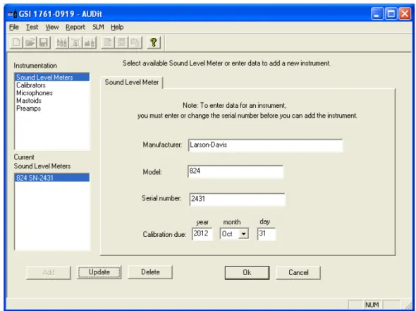
FIGURE 2-4 Instrumentation Screen
Types of instruments are listed in the upper left rectangle. Currently defined instruments (in this case, sound level meters) are listed in the rectangle at the lower left. The large area at the right has fields for model, serial number and other
AUDit Manual Entering Instrumentation 2-5
Sound Level Meter
Currently, the Larson Davis System 824 precision sound level meter (SLM) is the only SLM instrument compatible with the AUDit software. To enter your SLM information, click Test, Instrumentation... and select Sound Level Meters in the upper left box of the screen.
Enter the serial number of your 824 and its calibration due date; both available on labels on the back of the instrument. The calibration year must have four digits. Once all fields are completed, click Add. A new SLM entry will appear in the lower left box.
Calibrator
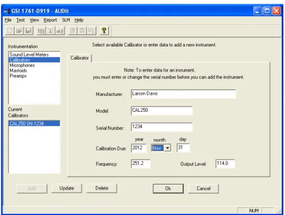
Calibrator information is entered by clicking Test, Instrumentation... and selecting Calibrators in the upper left box of the screen.
NOTE:The Larson Davis CAL250 cal-ibrator provided with your system has a frequency of 251.2 Hertz and a level of 114.0 dB re 20 micropascals. Output fre-quency and level are used by the AUDit the calibration procedure. Entering incorrect values could lead to measure-ment errors.
Enter the serial number of your calibrator, its calibration due date, frequency and output level. The calibration year must have four digits. Once all fields are completed, click Add.
Microphone
Microphone information is entered by clicking Test, Instrumentation... and selecting Microphones in the upper left box of the screen.
AUDit Manual Entering Instrumentation 2-7
Note: The 377A13 requires the polarization voltage set for Electret in the 824. In SETUP SLM Settings, set Transducer to Elctret.
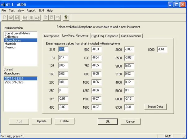
For 2575, 377A13 and 2559 microphones, data can be imported directly from a .csv file using the import data button. After importing the .csv file, click OK to save the imported data to the AUDit database.
For other microphones, frequency response information is available on the provided calibration chart and can be entered manually. Some audiometric frequencies may not be listed exactly: e.g. 200 Hz is listed as 199.53 Hz. If the frequency labeled in the software is between two frequencies on the certificate, you may wish to enter an interpolated value.
FIGURE 2-7 Microphone Frequency Response Information Dialog Box
High frequency and grid cap corrections may not be necessary if you are not performing the calibration of extended frequency audiometers.
Mic Larson-Davis 2575 1316 40.96 4/13/2009 20 0.43 25.1 0.36 31.6 0.29 39.8 0.23 50.1 0.18 63.1 0.14 79.4 0.1 100 0.07 125.9 0.05 158.5 0.03 199.5 0.01 251.2 0 316.2 -0.01 398.1 -0.02 501.2 -0.03 631 -0.04 794.3 -0.05 1000 -0.06 1059.3 -0.06 1122 -0.06 1188.5 -0.06 1258.9 -0.06 1333.5 -0.07 1412.5 -0.07 1496.2 -0.07 1584.9 -0.07 1678.8 -0.07 1778.3 -0.07 1883.7 -0.06 1995.3 -0.06 2113.5 -0.06 2238.7 -0.05 2371.4 -0.04 2511.9 -0.03 2660.7 0 2818.4 0
AUDit Manual Entering Instrumentation 2-9
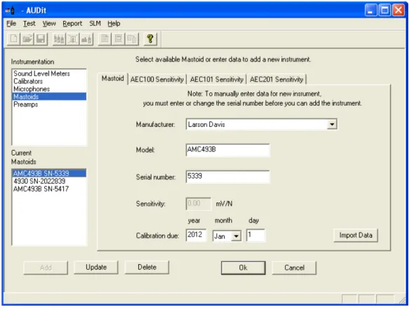
AMC493 Artificial Mastoid
The artificial mastoid is used to calibrate the bone vibrator used for bone conduction audiometry. Information is entered by clicking Test, Instrumentation... And selecting Mastoids
in the upper left box of the screen.
The sensitivity of a B&K mastoid is found on its calibration chart, under the heading Force Sensitivity (including cable) and is in units of mV/N.
Only two types of mastoids are currently supported by AUDit software: the Larson Davis Model AMC493 and Bruel & Kjaer 4930 artificial mastoids. Therefore, the Manufacturer entry is a pull down menu with those two choices. Enter the manufacturer, model and serial number of your mastoid and its calibration due date.
Field tests show the sensitivity offset for the AMC493 to be approximately 12.5 dB.
It is not necessary to enter a sensitivity with the Larson Davis artificial mastoid. AMC493B information can be imported directly from a .csv file using Import Data. The Bruel & Kjaer calibration chart typically has three parts. Enter values read from Page 2: Frequency Response at constant dynamic force, using the 5.4 N (black) curve.
AUDit Manual Entering Instrumentation 2-11
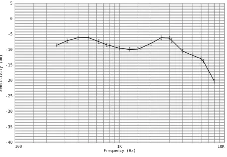
Sample Calibration Report
FIGURE 2-10 Sample Artificial Mastoid Response chart Artificial Mastoid Test Report: Sensitivity when used on an AEC201
Model: AMC493B Serial Number: 5021 AEC201 Serial Number: 0102
Tested without Black Conical Ring
Mastoid Sensitivity (reference: 20 µPa/µN)
Sensitivity (dB) 100 1K 10K Frequency (Hz) -40 -35 -30 -25 -20 -15 -10 -5 0 5
Frequency Sensitivity Uncertainty Frequency Sensitivity Uncertainty (Hz) (dB) (dB) (Hz) (dB) (dB) 250 -8.5 0.5 315 -7.0 0.6 400 -6.1 0.5 500 -6.0 0.5 630 -7.3 0.6 750 -8.4 0.5 800 -8.6 0.5 1000 -9.5 0.6 1250 -9.9 0.6 1500 -9.8 0.6 1600 -9.4 0.6 2000 -7.9 0.8 2500 -6.1 0.6 3000 -6.2 0.6 3150 -6.9 0.7 4000 -10.4 0.6 5000 -11.8 0.8 6000 -12.9 0.6 6300 -13.7 0.5 8000 -20.1 0.6 Temperature (°C): 23 ± 1 Relative Humdity (%): 49 ± 5
Static Pressure (kPa): 85.4 ± 2.0 (data corrected to 101.3 ± 3.0) Uncertainty at ~95% confidence level (k=2) Tested by Scott Montgomery on 2JUN2011
Test performed at: Larson Davis, a division of PCB Piezotronics, Inc. 1681 West 820 North, Provo, Utah 84601
Tel: 716 684-0001 www.LarsonDavis.com
The results documented in this report relate only to the item(s) tested.
Preamplifier
The Larson Davis System 824 precision sound level meter (SLM) is supplied with a Model PRM902 preamplifier. To enter your preamplifier information, click Test,
Instrumentation... And select Preamps in the upper left box of the screen.
AUDit Manual Preferences 2-13
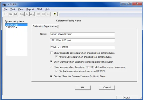
Preferences
This configuration item allows the entry of the calibrating organization and selection of communication parameters for the System 824 SLM.
Two system setup items are available in the rectangular area at the upper left of the screen as shown in FIGURE 2-13, Organization and RS232 Port.
FIGURE 2-13 Preferences Dialog Box
Organization • Click in the Name fields to enter information such as name and address.This information will appear on the report and calibration certificate.
AUDit Manual Preferences 2-15
• Checking the Show warning when there is no
RETSPL defined for a given frequency option will cause a warning message to appear before running a test without RETSPL defined for the frequency to be tested., as shown in Figure 2-14.
• Checking the Display frequencies when there is no RETSPL will allow the frequencies in the Hearing Level tests to be displayed without RETSPL being associated with them.
When RETSPL is not defined for the frequencies to be tested, the message shown in Figure 2-14 appears:
FIGURE 2-14 Frequencies without RETSPL
• Click Yes to display all frequencies, including those with our without RETSPL.
• Click No to close the dialog box to display only those frequencies with RETSPL.
• Click Cancel to uncheck the option to show this warning message until it is re-checked on the
Preferences dialog box.
• Checking the Display "Ears Not Covered" column for Booth Tests option will display columns in the 125 Hz to 8 kHz, 250 Hz to 8 kHz, and 500 Hz to 8 kHz booth tests and all of the reports.
Click RS232 Port to access the screen for RS232 communications port options. Here you may select port number (COM1 to COM8) and RS232 baud rate (300 to 115kBaud) from pull down menus.
FIGURE 2-15 RS-232 Communications Dialog Box
AUDit Manual 3-1
C H A P T E R
3
Audiometer Test Setup
For every audiometer test, the AUDit software allows you to fully define the measurement as well as the components of the equipment under test. When a measurement is defined, all this information is recorded in the database. Therefore, an audiometer system only needs to be defined once, saving a lot of time in subsequent tests.
In this chapter, you will set up the audiometer test by performing this data entry. You will be able to refer to instruments which were entered previously in the Instrumentation screen. Audiometers and their many transducer types will also be entered.
To begin entering test information, click the Test, Audiometer Test... drop down menu item. (FIGURE 3-1).
FIGURE 3-1
Test Menu
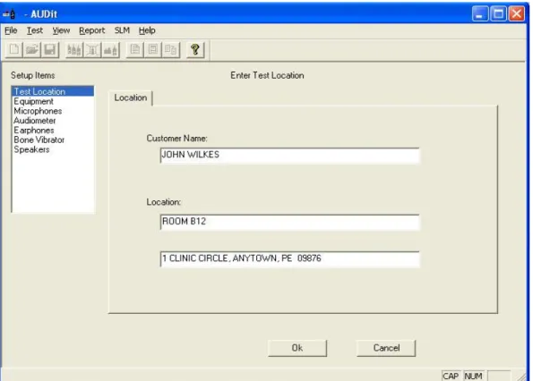
This will display the Enter Test Location screen (FIGURE 3-2). It is the first of a series of entry screens listed in a column on the left side of the screen.
Test Location
FIGURE 3-2 Test Location Dialog Box
This is where customer information is entered.
Test Location (FIGURE 3-2) contains the following fields: • Customer Name: the customer or company name
AUDit Manual Equipment 3-3
Equipment
NOTE: When the desired instrumenta-tion is selected for use with an audiome-ter measurement, a copy of the selected instrumentation is stored with the mea-surement. If changes are made to the instrumentation, those changes will not be reflected in the copy that is stored with the measurement.
The equipment used to test the audiometer is selected here from the instrumentation which was entered earlier. Equipment that has been previously entered into the instrumentation database is available for selection in these dialogs. To use a new piece of equipment in a test, first enter it into the instrumentation database then it can be selected here.
Mastoid Tab
FIGURE 3-3 Mastoid Selection Tab
The serial number is selectable from a drop down list of the previously entered serial numbers, which determines the Model and Manufacturer. The Larson Davis AMC493B and B&K 4930 artificial mastoids are supported by AUDit. The
two boxes at the bottom of the screen are active only for the appropriate mastoid.
Coupler for Larson Davis Mastoid
Since the Larson Davis AMC493B artificial mastoid requires corrections based on the coupler with which it is used, these radio buttons selects either the Larson Davis Model AEC201 or AEC100 coupler.
Mic used to calibrate the SLM
This box is only enabled with the Bruel & Kjaer artificial mastoid. It is used to specify which microphone will be used to calibrate the SLM before using the mastoid. Mastoid and microphone sensitivities are used to calculate the output level of the bone vibrator.
AUDit Manual Microphones 3-5
Microphones (FIGURE 3-4) allow you to configure the microphone paired with each coupler.
If a specific coupler will not be used in the audiometer calibration, no data entry is required.
AEC100 Mic Tab
Select the microphone used with the NBS 9A coupler. This coupler was originally developed by the National Bureau of Standards, now called the National Institute of Standards and Technology (NIST). It is specified in American National Standard Institute Specifications for Audiometers, S3.6-2004 for calibrating earphones used in audiometry. The Larson Davis AEC100 artificial ear is designed to meet the requirements of this standard.
AEC201 Mic Tab
Select the microphone PCB 377A13 used with the AEC201. This coupler is designed to achieve the characteristics defined in International Electrotechnical Commission IEC 60318-1:2009 Simulators of Human Head and Ear - Part 1: Ear Simulator for the calibration of supra-aural and circumaural earphones. The AEC201 also meets the requirements of the American National Standard ANSI S3.7-1995 (R2008) Method for Coupler Calibration of Earphones (Section 5.4). With the help of a circumaural adapter plate as described in IEC60318-1:2009 Annex B and ANSI S3.6-2004 Annex C, the AEC201 may also serve to calibrate specific high acoustic damping earphones.
AEC202 or AEC203 Mic Tab
Select the microphone used with the HA-1 coupler. This coupler is described in IEC 60126 (1973-01) IEC reference coupler for the measurement of hearing aids using earphones coupled to the ear by means of ear inserts. The coupler is designed to load the earphone with a specified acoustic impedance when determining the performance of air-conduction hearing aids using earphones coupled to the ear from 200 Hz to 5kHz.
AEC204 Mic Tab
Note: 126 and 711 have been replaced by IEC 60318-4 and -5. IEC60711 (1981) is canceled and replaced by IEC60318-4 (2010) and IEC 60126 (1973) is canceled and replaced by IEC 60318-5 (2006).
Select the microphone used with the IEC 60711 coupler. This coupler is described in IEC 60711 (1981-01) Occluded-ear simulator for the measurement of Occluded-earphones coupled to the ear by ear inserts. The standard specifies an occluded-ear simulator for the calibration of insert occluded-earphones from 100 Hz to 10 kHz.
Open Air Mic Tab
Select the microphone used for open air measurements such as the ambient noise level measurement of the Booth Test, or speakers tests.
AUDit Manual Audiometer 3-7
The Audiometer Description screen contains information on the audiometer (or signal generator) under test, while its transducers are defined in the remaining screens of the setup items. The Audiometer Description screen is composed of three different tabs to describe the audiometer and the frequencies at which it is tested.
Audiometers Tab
NOTE: American National Standard S3.6-2004 Specifications for Audiome-ters specifies the designation of audiom-eters (e.g. Type 3, Type 4) satisfying the standard. The minimum required facili-ties for each designation are listed in table 1 of the standard.
• Audiometer Type: Enter the audiometer type number, which should be stated in the audiometer specifications or labeled on the instrument itself. Additional suffixes for high frequency, speech or free field equivalent are not available but may be entered in the Audiometer Test Notes... comments.
NOTE: ANSI S3.6-2004 pure tone Type 1 and 2 audiometers must have a facility for presenting a frequency modu-lated tone.
• Carrier Frequency Modulation Rate Of: Enter the audiometer's frequency modulation percentage and rate of modulation. These values will be verified in the appropriate test.
Low Frequencies Tab
The Low Frequencies tab allows you to specify which audiometer frequencies will be tested. It contains a list of audiometer frequencies from 125 to 8000 Hz.
High Frequencies Tab
The High Frequencies tab allows you to specify which high frequencies available on the audiometer will be tested. These frequencies are used by extended high frequency pure tone audiometers.
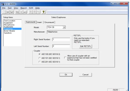
Earphones Screen
AUDit uses the supra-aural earphone reference equivalent threshold sound pressure levels (RETSPLs) in dB re 20 micropascals for common earphones as listed in Table 6 of ANSI S3.6-2004. The RETSPLs referred to the appropriate coupler are used in the calibration process. In the case of
AUDit Manual Earphones Screen 3-9
Use the Select Earphones dialog box (FIGURE 3-6) to specify the audiometer earphones information and the respective artificial ear couplers used in the test setup.
FIGURE 3-6 Select Earphones, Supra-aural Tab
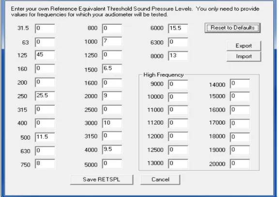
On this tab, you can also modify RETSPL values. Click the Edit RETSPL button to display the RETSPL Editing dialog box.
FIGURE 3-7 Editing RETSPL Values
RETSPL levels are defined by US or international standards. Changing levels may result in tests that are no longer compliant. To restore RETSPL levels to those defined by
• Clicking Reset to Defaults will undo any changes you made to RETSPL.
• Clicking Export will launch a Save dialog box to save modifications as a file for future use.
AUDit Manual 4-1
C H A P T E R
4
Booth Test or Ambient Noise
Level Test
You have now configured AUDit software in preparation for your first test. In this chapter, the system will be calibrated to perform a measurement of ambient levels in the audiometric test room. This is referred to as a Booth test in the AUDit software. In doing this test, we will also cover connecting to the SLM and calibrating it.
If ambient noise levels in an audiometric test room are excessively high, they can have a masking effect on the sub-ject, effectively raising the measured hearing threshold. This is most likely to occur if very low hearing threshold levels are being measured.
AUDit allows simultaneous assessment of noise levels for audiometric measurements with ears covered or not covered, in the frequency ranges of 125, 250 and 500 Hz to 8000 Hz. This test and its pass/fail limits are based on the recommen-dations of American National Standard on Maximum Per-missible Ambient Noise Levels for Audiometric Test Rooms, ANSI S3.1 - 1991 (R2008). It also allows assessment of ambient levels per OSHA 1915.95 Appendix D.
In order to consider the worst case conditions for an audio-metric test, the ambient noise test should be performed with all possible noise sources present. If certain sources are operating at certain times but not at others, it may be neces-sary to schedule the measurement accordingly.
Assembling the system
The Larson Davis System 824 precision sound level meter meets all the requirements of the aforementioned standards and rules for the measurement of ambient noise level in the audiometric test room. Its low self-noise and internal frac-tional octave band measurement capability enable it to accu-rately measure octave and third octave levels much below the minimum required levels, when using a high sensitivity microphone such as the Larson Davis model 2575.
Equipment for Booth Test
The equipment listed below is suggested for ambient noise testing using AUDit.
• PC with serial port with AUDit • CBL006 serial cable
• System 824 precision sound level meter
NOTE: The microphone/preamp assembly may be suspended or supported with a suitable microphone clamp. If the dimensions or construction of the audio-metric test room require a longer length of cable or the use of patch panels, care must be taken not to introduce ground loops or other problems which can lead to higher system self-noise levels.
• EXA010 extension cable (optional) • PRM902 preamplifier
• 2575 microphone
• ADP008 1/2 inch preamp to 1 inch microphone thread adaptor
AUDit Manual Assembling the system 4-3
Assembling the system
Step 1 Connect the CBL006 from the SERIAL connector on the butt plate of the 824 SLM to an active serial port on the computer.
Step 2 Install the PRM902 microphone preamplifier directly on the SLM or use the EXA010 extension cable by matching red dots on opposite gender connectors
FIGURE 4-2 Connecting EXA010 extension cable to 824 and PRM902
Step 3 Thread the ADP008 onto the PRM902 preampli-fier, being careful not to strip the threads
AUDit Manual Connecting the SLM 4-5
Step 4 Thread the 2575 or other microphone onto the PRM902 preamplifier, being careful not to strip the threads
FIGURE 4-3 Connecting PRM902, ADP008 and 2575 Microphone
Connecting the SLM
If AUDit is not active, run the software by clicking on the desktop icon or PCB Piezotronics AUDit (if AUDit was installed in the default folder). Verify communications port options in the Test, Preferences..., RS232 Port tab. The Sys-tem 824, and Audit must be configured with the same baud rate.
NOTE: The Communications settings on the System824 are accessed by
press-ing , scrolling to
Communica-tions, and pressing the key. Please refer to the 824 reference manual (I824.01) for complete instructions.
FIGURE 4-4 Connect Menu
Click SLM, Connect to establish connection with the SLM. You may verify battery level by clicking SLM, Check Battery... (Figure 4-4).
FIGURE 4-5 Battery Check Window
In this case the battery voltage is 12.2 Volts (Figure 4-5), with external power. Internal battery status is reported in percent. Measurements should not be attempted with inter-nal battery readings lower than 10%.
System Acoustic Calibration
NOTE: Calibrator and microphone must be selectecd as shown in the next section before calibration check or change
The reference level of the sound level meter is calibrated using a CAL250 or other precision calibrator. This instru-ment generates a known sound pressure level (SPL) relative to 20 µPa To calibrate, click SLM, Calibration.
AUDit Manual System Acoustic Calibration 4-7
FIGURE 4-6 SLM Calibration Window Hint: Do not hold or bump the
cali-brator during calibration. Vibrations may affect readings. All measure-ment system components should have reached a stable temperature before calibrating. Your calibrator should remain on for the duration of the calibration (about 30 seconds). If its battery is low, replace it to extend the tone duration.
AUDit will display the SLM Calibration dialog box. Select your calibrator and microphone in the pull down menus. Note that the current level and the difference between it and the calibrator output level are displayed at the top of the box.(Figure 4-6) You may use this display to check calibra-tion without changing it, then click on Close to exit. To change calibration click Set Calibration.
Performing a Booth Test
Once the SLM has been calibrated, the ambient noise levels can be measured. Select the Test, Booth Test menu item to display the Booth Ambient Levels Measurement screen.
AUDit Manual Performing a Booth Test 4-9
NOTE: A message (Figure 4-10) will be displayed while the measurement is performed.
FIGURE 4-8 Ambient Level Test Message Window
125 - 8K Hz, 250 - 8K Hz, and 500 - 8K Hz and OSHA Tabs
NOTE: The limits used in these tabs are from Tables III and B2 of the Ameri-can National Standard on Maximum Per-missible Ambient Noise Levels for Audiometric. The OSHA limits are from OSHA 1910.95 Appendix D
Once the measurement is completed, these three tabs show Booth Test results.(Figure 4-11) Failed frequencies are indi-cated with a red mark. In this case, the failed 125 Hz third octave measured SPL was 26.9 dB SPL, whereas the stan-dard allows (at most) 30.0 for covered, and 24.0 for not cov-ered ears. The exceeded limit values are displayed between parentheses.
Saving a Booth Test
Once the test is complete, you may save it by clicking OK at the bottom of the Booth Ambient Levels Measurement screen, which will display the dialog box shown in (Figure 4-12.
AUDit Manual Suspecting Instrument Noise? 4-11
Suspecting Instrument Noise?
Should the readings of the ambient test be questionable, you may want to check the measurement system noise. There are a few ways to do this. One simple alternative is to repeat the measurement with the non-activated calibrator left on top of the microphone. Another is to do the booth test without a bias voltage on the microphone. This has the effect of reduc-ing its sensitivity and will show the electrical noise of the system. The results of this first method are shown in . FIG-URE 4-11. The failed 125 Hz third octave measured SPL was 25.9 dB SPL.
FIGURE 4-11 Booth Ambient Levels Window
As you can see, the noise level at the third octave centered at 125 Hz is 4.4 dB SPL, well below the failing ambient level.
This would indicate that the noise was not produced in the instrumentation.
Hint: To remove the bias voltage
from the microphone, stop the 824
and press (Setup), (Right
Arrow) to modify the Audtest.AUD
settings. Scroll to SLM, press
(Right Arrow) and scroll down to
modify SLM parameter Transducer. Press the (Check key) and per-form an Overall Reset to select Elc-tret. Remember to rest the transducer to condnser before making new mea-surements.
This measurement has demonstrated the ease of use of the Larson Davis audiometer calibration system. In the remain-der of this manual, a full audiometer calibration will be per-formed.
AUDit Manual Audiometer Test System Assembly 5-1
C H A P T E R
5
Audiometer Test System
Assembly
The setup defined for each trans-ducer earlier in the AUDit software as described in the Audiometer Test Setup chapter. This will ensure the proper microphone corrections, RETS PL's etc. are applied to the measurement.
This chapter covers test configurations for the audiometer transducers which can be calibrated by the LD audiometer calibration systems. The recommended configurations for various earphones will be described first. Common elements such as the PC to System 824 SLM and PRM902 preamplifier connections, inspection and calibration procedures are explained next. Please contact Larson Davis if you have any system assembly questions not covered in this manual.
Audiometer Transducer Test Configurations
The table below lists some typical audiometer transducers, many of which are covered in specifications such as
American National Standards Institute Specifications for Audiometers, S3.6-2004. When configuring the audiometer transducer test, the AUDit software suggests or defaults to appropriate setups. These test setups are covered in greater detail in subsequent sections.
Transducer Type Example Suggested Setup Comments Supra-aural earphone Telephonics TDH-39,
49, 50
AEC100 NBS 9-A cou-pler or AEC201 IEC 60318 Ear Simulator
Use 4-5 N weight. Test up to 8000 Hz. Circumaural earphone Sennheiser HDA200 AEC201 IEC 60318 Ear
Simulator with MAEC101.06 Type 1 adaptor plate
Use 9-10N weight. Extended frequency tests up to 16000 Hz may be performed.
Circumaural earphone Koss HV/1A AEC201 IEC 60318 Ear Simulator with MAEC101.07 Type 2 adaptor plate
Use 9-10N weight. Extended frequency tests up to 16000 Hz may be performed.
Bone vibrator Radio Ear B-71 AEC100 NBS 9-A cou-pler or AEC201 Ear Simulator and AMC493B Artificial mastoid
Use 9-10N weight
Speakers Speakers Use ambient noise level test setup from Chapter 4.
Insert earphone Insert Earphone AEC202 or AEC203 2.0 cm3 or Type 2 coupler
AEC204 ear simulator
Refer to earphone and coupler manufacturer information.
AUDit Manual Connect the PC, 824 and PRM902 Preamplifier 5-3
Step 1 Connect the CBL006 RS-232 cable from the SERIAL connector on the butt plate of the 824 to an active RS-232 port on the computer (FIGURE 5-2).
FIGURE 5-2 Connecting CBL006 to 824 Step 2 Connect the male end of the EXA010 extension
cable to the nose cone of the 824 by matching the red dots on mating connectors (FIGURE 5-3).
FIGURE 5-3 EXA010 extension cable approaching System 824
Step 3 After the PRM902 microphone preamplifier has been inserted and treated in the appropriate cou-pler, (see below) connect it to the nose cone of the
824 with the EXA010 extension cable by match-ing the red dots on matmatch-ing connectors (FIGURE 5-4).
FIGURE 5-4 Preamp connecting to extension cable and to AEC100
Step 4 The 824 SLM may now be turned on by parame-ters. Pressing the key on the 824.
Step 5 Press , scroll down with the to Commu-nication and press to edit Serial Comm. parameters. Set the parameters as desired. 9600 Baud, serial address 000 and Hdwr flow control are suggested.
AEC100 Coupler Assembly and Calibration
AUDit Manual AEC100 Coupler Assembly and Calibration 5-5
AEC100 Initial Assembly
WARNING! Before continuing, ensure that the 824 SLM is turned off. The 824 should remain off until the system is fully assem-bled.
The AEC100 artificial ear is an elegant, compact precision coupler built to provide a lifetime of dependable use with reasonable care. Read the following instructions to unpack, inspect and assemble the coupler for the first time.
Step 1 Place the cushioned vibration isolation pad on a table or other such stable surface near the audiom-eter system.
Step 2 Visually inspect the coupler (MAE100.1) for gouges, scratches and dents which may affect the measurement, especially around the lip which will be in contact with the test earphone. Verify that the small metallic wire in the capillary leak hole is present with no other obstructions (FIGURE 5-5).
FIGURE 5-5 AEC100 with coupler, leak hole
MAE100.1 6 cc coupler MAE100.3 1 inch coupler cap SP-MAE100.40 Artificial ear base MAE100.6 Earphone retainer ring
MAEC100.7 Mass handle screws into SAEC100.01 SAEC100.01 Weight assembly and rubber no handle ACC001 Vibration isolation pad Part Number Description
Step 3 If installed, remove the coupler cap (MAE100.3) from the artificial ear base (SP-MAE100.40) by gently unscrewing it counterclockwise (FIGURE 5-6).
FIGURE 5-6 Protective ring being removed from AEC100
Step 4 Inspect a spring-loaded contact at the center of the base visually. It should extend approximately 5 mm above the threaded ridge. The insulator around it should be free of dust and other particles. Please do not handle the contact and protect it by keeping the coupler cap on whenever a micro-phone is not installed.
Step 5 Install the 1" microphone (LD Model 2575 or equivalent) on the center of the artificial ear base. The microphone should install easily: screw it fin-ger tight (FIGURE 5-7).
AUDit Manual AEC100 Coupler Assembly and Calibration 5-7
tight (FIGURE 5-8). Connect the instrument cable to the preamplifier. The coupler is now ready for level calibration.
FIGURE 5-8 Preamp connecting to AEC100 and Extension Cable
AEC100 Acoustic Calibration
It is necessary to remove the calibra-tor 1/2 inch adapcalibra-tor (ADP019) ring from the CAL250 to allow the one inch microphone to fit inside the cal-ibrator one inch opening.
Level calibration is performed with the Larson Davis Model CAL250 precision calibrator. It offers a level of 114 dB with an accuracy of +/-0.2 dB at 251.2Hz. To calibrate the measurement system and artificial ear, follow the procedure below.
Step 1 Assemble the coupler as described in the AEC100 Acoustic Calibration on page 5-7 section above. The coupler base should rest on the isolation pad and ambient noise and vibration should be mini-mized.
Step 2 Place the calibrator opening on the microphone and seat it fully (FIGURE 5-9). Note: Do not remove the microphone grid cap.
FIGURE 5-9 CAL250 being lowered onto 2575 microphone
Step 3 Activate the calibrator as prompted by the soft-ware and verify the stability of the indication on the measurement system (FIGURE 5-10). Do not
AUDit Manual AEC100 Coupler Assembly and Calibration 5-9
hold the calibrator during calibration. Its tone will last about one minute (depending on the battery) and will turn off automatically.
FIGURE 5-10 Starting Calibration tone with on switch
In actual practice, for most testing, the grid cap does not need to be removed. This will help reduce the possibility of accidental damage to the delicate and expensive precision microphone diaphragm.
Step 4 AUDit requires a calibration in each of two mea-surement ranges. The calibrator tone may have to be reactivated for the second calibration as prompted by the software.
Step 5 See Note at left before proceeding. After the cali-bration, carefully remove the grid cap by holding the microphone body and unscrewing the grid counterclockwise (FIGURE 5-11). Store it in the microphone case.
FIGURE 5-11 Removing grid cap from 2575 Microphone
Step 6 Replace the grid cap with the protective coupler cap (MAE100.3), being careful not to impact the delicate diaphragm (FIGURE 5-12).
FIGURE 5-12 Installing Protective Ring on 2575 Microphone
AEC100 Final Assembly for Testing Supra-Aural Earphones
The following steps are suggested for audiometer calibration with the AEC100.
Step 1 Assemble the coupler as described in the AEC100 Coupler Assembly and Calibration on page 5-4. The coupler base should rest on the isolation pad and ambient noise and vibration should be mini-mized.
Step 2 Perform a calibration of the system as described in AEC100 Coupler Assembly and Calibration on page 5-4 and replace the microphone grid cap with the protective coupler cap (MAE100.3), being
AUDit Manual AEC100 Coupler Assembly and Calibration 5-11
.
FIGURE 5-13 Coupler being installed on AEC100 Step 3 Center the test earphone on the coupler. Lower the
black retainer ring over the earphone, holding the earphone cable in line with the notch (FIGURE 5-14).
FIGURE 5-14 Retainer Ring being installed over headphone.
Step 4 Lower the mass by its handle to the top of the ear-phone (FIGURE 5-15).
FIGURE 5-15 Mass being installed on AEC100.
The coupler and earphone are now ready for measurement.
AEC201 Ear Simulator and Assembly and Calibration
For this you will need:
Part Number Description
AUDit AUDit software running on a PC CBL006 Serial cable 8 pin mini DIN to DB-9
824 System824 precision sound level meter (SLM) EXA010 10 foot extension cable with 7 pin LEMO connectors 377A13 1/2" precision air condenser random incidence microphone PRM902 1/2" diameter low noise microphone preamplifier
CAL250 or CAL200 Precision SPL calibrator with 114 dB SPL output at 250 Hz with 1" to 1/2" calibrator opening adaptor (ADP019)
AUDit Manual AEC201 Ear Simulator and Assembly and Calibration 5-13
AEC201 Initial Assembly
WARNING! Before continuing, ensure that the 824 SLM is turned off. The 824 should remain off until the system is fully assem-bled.
The AEC201 artificial ear is a versatile coupler and allows measurement of a variety of earphones with its provided accessories. Read the following instructions to unpack, inspect and assemble the coupler for the first time.
Step 1 Place the cushioned vibration isolation pad on a table or other such stable surface near the audiom-eter system.
Step 2 Visually inspect the coupler for gouges, scratches and dents which may affect the measurement, especially around the sharp lip which will be in contact with the test earphone. Verify that the small tube in the capillary leak hole is present with no other obstructions (FIGURE 5-16).
FIGURE 5-16 AEC201 with coupler, leak hole
AMEC101.10 Bag Weight 9.5 Newton (946g) Part Number Description
Coupler
Leak Hole contact Loaded Spring
Step 3 If installed, remove the coupler from the artificial ear base by gently unscrewing it counterclock-wise.
Step 4 Inspect the spring-loaded contact at the center of the base visually. It should extend approximately 5 mm above the threaded ridge. The insulator around it should be free of dust and other particles. Please do not handle the contact and protect it by keeping the coupler on whenever a microphone is not installed.
Step 5 Install the 1/2" microphone PCB model 377A13 on the center of the artificial ear base. The micro-phone should install easily: screw it finger tight (FIGURE 5-17)
.
AUDit Manual AEC201 Ear Simulator and Assembly and Calibration 5-15
When removing the preamplifier, unscrew it by holding on its body, not the connector sleeve
FIGURE 5-18 Preamp approaching AEC201 Step 7 Connect the instrument cable to the preamplifier.
The coupler is now ready for level calibration.
AEC201 Acoustic Calibration
You will need to install the adapter (ADP019) into the CAL250 in order to calibrate 1/2 inch microphones.
Level calibration is performed with the Larson Davis Model CAL250 precision calibrator. It offers a level of 114 dB with an accuracy of +/-0.2 dB at 251.2 Hz. You will have to insert the provided 1" to 1/2" adaptor in the top of the calibrator. To calibrate the measurement system and artificial ear, follow the procedure below.
Step 1 Assemble the coupler as described in AEC201 Ear Simulator and Assembly and Calibration on page 5-12. The coupler base should rest on the isolation pad and ambient noise and vibration should be minimized.
Do not remove the microphone grid cap.
Step 2 Place the calibrator opening on the microphone and seat it fully (FIGURE 5-18).
FIGURE 5-19 Installing the CAL250 on AEC201 Step 3 Activate the calibrator as prompted by the
soft-ware and verify the stability of the indication on the measurement system (FIGURE 5-19). Do not hold the calibrator during calibration. Its tone will last about one minute (depending on the battery) and will turn off automatically.
AUDit Manual AEC201 Ear Simulator and Assembly and Calibration 5-17
Step 4 AUDit requires a calibration in each of two mea-surement ranges. The calibrator tone may have to be reactivated for the second calibration as prompted by the software.
AEC201 Final Assembly for Testing Supra-Aural Earphones
The following steps are suggested for audiometer calibration with the AEC201.
Step 1 Assemble the coupler as described in AEC201 Ear Simulator and Assembly and Calibration on page 5-12. The coupler base should rest on the isolation pad and ambient noise and vibration should be minimized.
Step 2 Perform a calibration of the system as described in AEC201 Acoustic Calibration on page 5-15.
Step 3 Screw the coupler over the base (FIGURE 5-21) until finger tight.
FIGURE 5-21 Coupler being installed on AEC201 Step 4 Place the black conical ring (FIGURE 5-22) on the
top of the coupler.
FIGURE 5-22 Black Conical ring installed on AEC201
Step 5 Center the test earphone on the coupler. Lower the black retainer ring over the earphone, holding the earphone cable in line with the notch (FIGURE 5-23).
FIGURE 5-23 Retainer ring being installed on AEC201
Step 6 Lower the mass by its handle to the top of the ear-phone (FIGURE 5-24).
FIGURE 5-24 Mass being lowered onto headphone
AUDit Manual AEC201 Ear Simulator and Assembly and Calibration 5-19
RETSPLs for two circumaural earphones are listed in Annex C of ANSI S3.6-2010. These two types of cirumaural earphones are available in AUDit: the Sennheiser HDA200 and Koss HV/1A.
Environmental conditions
It is stated in various standards that the extended high-frequency calibration of circumaural earphones be performed only when the following environmental conditions are met.
AEC201 Configuration
The following steps are suggested for circumaural earphone audiometer calibration with the AEC201.
Step 1 Assemble the coupler as described in theAEC201 Ear Simulator and Assembly and Calibration on page 5-12. The coupler base should rest on the iso-lation pad and ambient noise and vibration should be minimized.
Step 2 Perform a calibration of the system as described in AEC201 Acoustic Calibration on page 5-15.
Step 3 Screw the coupler over the base (FIGURE 5-25).
FIGURE 5-25 Coupler being installed on AEC201 Step 4 For earphones designed to be calibrated with a
Type 1 adapter such as the Sennheiser HDA200, install the Type 1 adapter on the coupler, with the
Condition Range in ANSI S3.6-2010 (Annex C)
Range in IEC 60318-1:2009 Clause 6 Calibration Ambient Pressure 98 to 104 kPa 98.325 to 104.325 kPa Temperature 18 to 26 degrees C 20 to 26 degrees C Relative Humidity 30 to 80% RH 30 to 70% RH Any condition not met Calibration is not allowed State actual values
cylindrical rim facing down. Place the black coni-cal ring on the top of the coupler and plate, with its flat base on the bottom (FIGURE 5-26).
FIGURE 5-26 AEC201 with Type 1 Adapter installed
Step 5 For earphones designed to be calibrated with a Type 2 adapter such as the Koss HV/1A, use the Type 2 adapter, which has crenellated distance clamps around its circumference. Do not use the black conical ring (FIGURE 5-27).
FIGURE 5-27 Type 2 adapter installed on AEC201 Step 6 Center the test earphone on the coupler or place it as recommended if the cushion is asymmetrical.
AUDit Manual AMC493B Assembly for Testing Bone Vibrators 5-21
Step 7 ANSI S3.6-2010 requires a static force of 9 to 10 N on the earphone during calibration. Use the large weight bag (FIGURE 5-28).
FIGURE 5-28 Sennheiser earphone and weight bag being installed on AEC201
The coupler and earphone are now ready for measurement.
AMC493B Assembly for Testing Bone Vibrators
Bone vibrators are used to test sound conduction through the head. Their use is limited to a restricted frequency range. The LD AMC493B artificial mastoid uses an innovative
design to allow bone vibrator calibration using an AEC100 or AEC201. The AMC493B converts the force applied by the bone vibrator to an acoustic signal which can then be measured acoustically by the calibration system. The following steps are suggested for bone vibrator transducer calibration.
In addition to the components of the AEC100 or AEC201, you will need the following equipment:
Environmental conditions
Bone vibrator calibration measurements are extremely sensitive to temperature and humidity. One important advantage of the AMC493B is its very low thermal mass, which allows it to stabilize to the temperature of the test area very quickly, typically within a few tens of minutes. The sensitivity and mechanical impedance data supplied for the AMC493B were measured at 23 °C and 50% RH.
The basis for ANSI Standard S3.13-1987 (Reaffirmed 1993) Mechanical Coupler for Measurement of Bone Vibrators is IEC 60373:1990-01 of the same name. This standard states that in general, temperature correc-tions can not be used directly to cor-rect data not taken at the reference temperature of 23 degrees C, as the effect of temperature on the bone vibrator is unknown. See also
Although AUDit performs a temperature correction, it is recommended to make measurements as close as possible to the temperature at which the AMC493B mastoid was calibrated.
Except during use, the AMC493B is kept in a case with temperature and humidity meter. Place these temperature and humidity number corrections in the AUDit software, along with the local pressure, to enhance the mastoid accuracy.
Part Number Description AMC493B Artificial mastoid MAE100.55 Additional ring mass
AUDit Manual AMC493B Assembly for Testing Bone Vibrators 5-23
Step 4 Lightly place the AMC493B artificial mastoid on the top of the coupler (FIGURE 5-29) with ring-shaped polymer.There must not be any metal to metal contact. Press down slightly on the AMC493B to secure its position.
Step 5 Center the test vibrator contact surface on the cir-cular resilient surface of the AMC493B. Ensure that there is no contact between the vibrator body and the AMC493B metallic rim (FIGURE 5-30).
FIGURE 5-30 Vibrator being placed and centered on mastoid
AUDit Manual AMC493B Assembly for Testing Bone Vibrators 5-25
Step 6 Assemble the additional mass ring over the handle of the AEC100 mass (FIGURE 5-31)
FIGURE 5-31 Additional mass being placed on AEC100 weight
When removing the AMC493B artifi-cial mastoid from the coupler, gently twist it off to break the seal. For more information, refer to the AMC493B manual.
Step 7 Lower the black retainer ring over the vibrator, holding the vibrator cable in line with the notch (FIGURE 5-32).
FIGURE 5-32 Retainer Ring being placed over vibrator
Step 8 Lower the mass on top of the vibrator by its handle (FIGURE 5-33).
FIGURE 5-33 Artificial ear with vibrator and mass installed
The coupler and vibrator are now ready for measurement. Set tone type, level and presentation and make the reading on the measurement system.
B&K
4930 Assembly for Testing Bone Vibrators
Unlike the LD AMC493B, the Brüel & Kjær artificial mastoid uses an accelerometer to measure the bone vibrator output. The LD audiometer calibration system can interface with the B&K mastoid by using the high input impedance PRM902 preamplifier and a suitable adapter.
AUDit Manual AMC493B Assembly for Testing Bone Vibrators 5-27
Larson Davis recommends making measurements as close as possible to the temperature at which the artificial mastoid was calibrated.
Test Configuration
Step 1 Assemble the measurement system as in the sec-tion on: Connecting the PC, 824 and PRM902 Pre-amplifier.
Step 2 Thread the ADP008 onto the preamplifier and then thread the 2575 microphone on the preampli-fier (FIGURE 5-34).
FIGURE 5-34 ADP008 being installed on PRM902 Step 3 Perform a system SPL calibration using the
CAL250.
824 System824 precision sound level meter (SLM) PRM902 1/2" diameter low noise microphone preamplifier ADP008 1" microphone to 1/2" preamp adapter
2575 1" precision air condenser microphone
CAL250 Precision SPL calibrator with 114 dB SPL output at 250 Hz B&K 4930 Artificial Mastoid and accessories
ADP007 or ADP006
Microdot to 1/2" preamp adapter for charge-coupled accelerome-ter or BNC to 1/2" microphone thread adapaccelerome-ter, 47 if with shorting cap
Step 4 Remove the ADP008 adaptor and 2575 micro-phone, and replace them with the appropriate adaptor to connect to the artificial mastoid (FIG-URE 5-35).
FIGURE 5-35 Adapters to connect to B & K mastoid
Step 5 Install the bone vibrator on the B&K 4930 as described in the B&K user manual.
The coupler and vibrator are now ready for measurement. ADP007
AUDit Manual Hearing Level Test 6-1
C H A P T E R
6
Hearing Level Test
Once AUDit has been configured with the test instrumentation and audiometer information, an actual audiometer calibration may be performed. The main measurement screen is accessed from the Audiometer Test Setup screen by pressing the OK button.
Calibration Main Measurement Screen
FIGURE 6-1 Main Measurement Screen
The main measurement screen allows one to enter the test date and technician name. The tested audiometer manufacturer, model and serial number are displayed as
entered in the previous setup. A table of tests and transducers shows the available tests for the particular audiometer. For example, the Hearing Level test may be performed with supra-aural, insert or circumaural earphones, as well as with the bone vibrator and speakers. Appropriate corrections are applied within each test using microphone, coupler and standard adjustments.
The SLM should be calibrated before a measurement is performed.
To begin the audiometer calibration process, highlight the
Hearing Level test with the pointer and press the Go To Measurement button. If you are already in a test screen, press the same test in the Measurements window at the upper left.
AUDit Manual Hearing Level Test with Earphone Transducers 6-3
Hearing Level Test with Earphone Transducers
FIGURE 6-2 Hearing Level Screen
The Hearing Level screen is typical of the measurement screens. On the left, below the measurement table, you will find the list of transducers for which the audiometer hearing level may be tested. The large box at the right has multiple tabs and varies according to the transducer being tested. For example, all earphones types have four tabs: Low and High Freq. Input levels, Left and Right. On the other hand, the bone vibrator has only two tabs: Input levels and Bone Vibrator Levels. In this section, the supra-aural earphone transducers will be calibrated. The procedure is the same for insert and circumaural earphones.