Finite Element Analysis of the Effect of Superstructure Materials and
Loading Angle on Stress Distribution around the Implant
Jafari K
a, Vojdani M
b, Mahdavi F
a, Heidary H
aa. Department of Prosthodontics, Shiraz Dental School, Shiraz University of Medical Sciences, Shiraz, Iran b. Biomaterial Research Center, Shiraz Dental School, Shiraz University of Medical Sciences, Shiraz, Iran
A R T I C L E I N F O Abstract
Article History
Received: 13 Aug 2014 Accepted: 12 Nov 2014
Statement of Problem: A general process in implant design is to determine the reason of possible problems and to find the relevant solutions. The success of the implant depends on the control technique of implant biomechanical conditions.
Objectives: The goal of this study was to evaluate the influence of both abutment and framework materials on the stress of the bone around the implant by using three-dimensional finite element analysis.
Materials and Methods: A three-dimensional model of a patient’s premaxillary bone was fabricated using Cone Beam Computed Tomography (CBCT). Then, three types of abutment from gold, nickel-chromium and zirconia and also three types of crown frame from silver-palladium, nickel-chromium and zirconia were designed. Finally, a 178 N force at angles of zero, 30 and 45 degrees was exerted on the implant axis and the maximum stress and strain in the trabecular, cortical bones and cement was calculated.
Results: With changes of the materials and mechanical properties of abutment and frame, little difference was observed in the level and distribution pattern of stress. The stress level was increased with the rise in the angle of pressure exertion. The highest stress concentration was related to the force at the angle of 45 degrees. The results of the cement analysis proved an inverse relationship between the rate of elastic modulus of the frame material and that of the maximum stress in the cement.
Conclusions: The impact of the angle at which the force was applied was more significant in stress distribution than that of abutment and framework core materials. Keywords:
Finite element analysis Stress
Strain Core material Abutment material
Corresponding Author:
Farideh Mahdavi
Department of Prosthodontics, Dental School,
Shiraz University of Medical Sciences, Shiraz, Iran Tel: +98-9132748980
Email: [email protected]
Cite this article as: Jafari K, Vojdani M, Mahdavi F, Heidary H. Finite Element Analysis of the Effect of Superstructure Materials and Loading Angle on Stress Distribution around the Implant. J Dent Biomater, 2014;1(2):57-62.
Introduction
Implant is the second oldest branch in dentistry next to exodontia (dental extraction). The history of root-shaped implants dates back to thousands of years ago [1]. The twentieth century was the beginning of important and fundamental changes in implant dentistry [2-4].
Dental implants differ from the natural teeth in transmission of functional forces to the jawbone. In a natural tooth due to the presence of periodontal
ligament and also the shape of the root, it is possible to have little movement. Also the vertical occlusal forces are in a way that puts the center of tooth rotation at 1/3 apically. An implant has a different biomechanical behavior. In an implant due to the osteointegration process and lack of periodontal ligament, there is no little movement like the one in a natural tooth to distribute the forces evenly [5].
Attention to biomechanical rules in prostheses supported implants makes it possible to present suitable treatment plans for individual patients.
Therefore, it results in a decrease in the probability of functional problems or implant failure [6]. Transmission of the exerted force on the implant and the surrounding bone depends on factors such as the force type, implant-bone connection, implant length and diameter, prosthesis type and quantity and quality of the bone surrounding the implant [7]. The application of engineering knowledge in dentistry has contributed to understanding the implant treatment biomechanical rules. The analysis of the stress level around the abutment, implant and prosthesis elements can prevent the failure of the treatment plan by predicting the stress transmission pattern [6, 7].
The common techniques applied to evaluate the stress transmission pattern include photoelastic stress analysis, strain gauge analysis, and finite element analysis [8]. Finite element analysis is an approach to evaluate mechanical behavior in complex structures. In this approach, the selected structure is divided into smaller elements. Each element’s mechanical behavior is predictable from the mechanical properties which are defined for that material. According to mathematical theorem in mechanics, when an element is under pressure, based on the pre-defined mechanical properties, its shape will be changed [9]. These elements are connected to each other via nodes and, as a result, the total structure is affected. Because the implant and bone geometry has a very complex structure, we can carefully measure the resulting changes caused by the applied forces on each surface by adopting finite element analysis [9, 10].
The most prominent features of applying finite element analysis are its repetitiveness, low costs, diversity in different analyses design, adaptability to various clinical conditions, high precision, lack of any need to sophisticated equipment and also the possibility of design and analysis in individually
custom-made implants. It should be taken into consideration that finite element analysis is a sheer numerical approach based on pre-defined hypotheses. Using this method can help to determine stress and strain in three-dimensional structures [11]. In recent years, finite element analysis has been a suitable tool in evaluation and prediction of stress transmission pattern in the implant and surrounding bone [12, 13]. A general process in implant design is determining the cause of possible problems and then finding a solution to resolve it. The level of implant success depends on the control method of biomechanical conditions in which the implant functions [12] and also the way that stress is transmitted from the implant to the bone [8].
Research is lacking in regard to the effect of both abutment and core materials together on stress distribution in the implant supporting bone. Therefore, the aim of this study was to evaluate the impact of both abutment and framework materials on stress distribution produced in the bone surrounding the implant using three-dimensional finite element analysis.
Materials and Methods
In the first stage, the CBCT of an edentulous 55-year-old man was used to make a three-dimensional model of the premaxillary bone. The data was transferred to Mimics 10.01 software. The default threshold for the bone was selected. Finally, the three-dimensional model was saved in stereolithiography (STL) format. This three-dimensional model was then transferred to CATIA software and edited (Figure 1).
In this study, the quality of D3 premaxillary bone area was considered and designed with two cortical (with the thickness of 0.75 mm) and trabecular layers. Nobel Replace Tapered (Nobelpharma, Gothenburg,
Sweden) implant was selected for designing in this study. The required design dimensions were available in the manufacturer’s catalogue.
The length of the selected implant was considered to be 13 mm, its diameter 4.3 mm, the abutment height 7.5 mm, and the collar area height 1 mm. The margin was designed as scalloped in order to comply with the soft tissue profile. Zinc oxide Eugenol (ZOE) cement of 20 µm thicknesses was designated between the abutment and crown frame. The crown was designed to have two parts: a frame of 0.4 mm thickness and porcelain with the thickness of 1.5 mm. Porcelain contour was designed according to normal morphology to be 10 mm cervicoincisally, 8 mm mesiodistally, and 7 mm labiopalatally.
This study was conducted on three groups as follows:
Group 1: UCLA abutment from silver- palladium and porcelain fused to metal (PFM) crown with a silver-palladium frame and loading at zero, 30 and 45 degrees.
Group 2: UCLA abutment from nickel-chromium (Ni-CR) and PFM crown with a nickel-chromium frame and loading at zero, 30 and 45 degrees
Group 3: Abutment from zirconia (Zr) and an all-ceramic crown with zirconia core and loading at zero, 30 and 45 degrees
The designed model in CATIA software was transferred to ANSYS Workbench 14 software for performing finite element analysis (Figure 2).
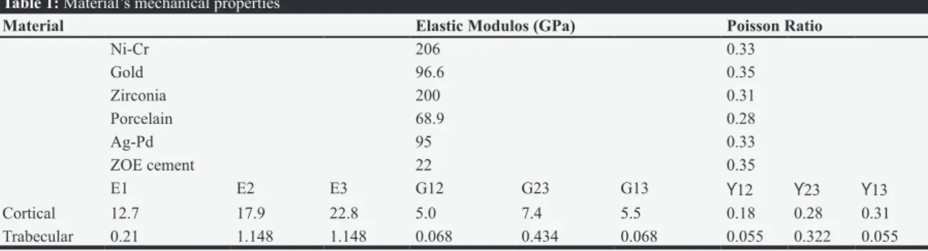
The material’s mechanical properties including elastic modulus and Poisson’s ratio were defined, as shown in Table 1.
In this analysis, for the mechanical properties of the bone, anisotropy and non-linearity, and for other materials homogeneity, elasticity, and linearity were taken into consideration.
In applying a force at zero degrees angle, a 178 N force was exerted on the incisal edge parallel to the implant axis (Figure 3). For applying the angulated forces, the place of exerting the force was 2 mm below the incisal edge and on the top of the cingulum area.
Results
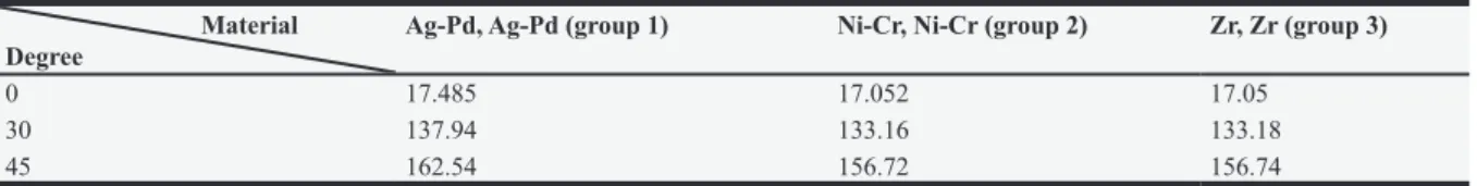
The results of finite element analysis as Von-Mises stress in various structures are illustrated in Table 2.
In the cortical bone of various groups, with changes in materials, abutment, and frame mechanical properties, a very slight difference was observed in the stress level and its distribution. Maximum stress level was increased with the increase in the angle at which the force was applied. Stress concentration was related to the force at 45 degrees angle.
In applying the force at zero, the least stress was in group 3 and the most in group 1. In applying the force at 30 degrees, the least stress was in group 2 and the most in group 1. In applying the force at 45 degrees, the least stress was in group 2 and the most in group 1. The highest stress level in the cortical bone was observed in the labial crest area. The stress distribution pattern in the cortical bone was symmetrical in the Figure 2: The prepared 3-D model in ANSYS Work Bench 14
Figure 3: Force Application at 0 degrees angle to the implant axis
Table 1: Material’s mechanical properties
Material Elastic Modulos (GPa) Poisson Ratio
Ni-Cr 206 0.33
Gold 96.6 0.35
Zirconia 200 0.31
Porcelain 68.9 0.28
Ag-Pd 95 0.33
ZOE cement 22 0.35
E1 E2 E3 G12 G23 G13 ϒ12 ϒ23 ϒ13
Cortical 12.7 17.9 22.8 5.0 7.4 5.5 0.18 0.28 0.31 Trabecular 0.21 1.148 1.148 0.068 0.434 0.068 0.055 0.322 0.055
mesial and distal directions. The three groups were similar with respect to the stress distribution pattern in the cortical bone.
The evaluation of strain in the cortical bone demonstrated that the change of materials in the abutment and frame led to minor differences in the different groups (Table 3).
In applying the force at zero, the least amount of microstrain was seen in group 3 and the most in group 1. In applying the force at 30 degrees, the least amount of microstrain was observed in group 2 and the most in group1. Also, in applying the force at 45 degrees, the least amount of microstrain was in group 2 and the most in group 1. The highest concentration of strain in the cortical bone was observed in the direction of the labial crest.
In the trabecular bone, the stress concentration was observed in the cervical half of the implant and the stress level and distribution did not change noticeably with the change in the abutment and frame materials. The maximum strain in the trabecular bone was detected in the implant apex area. Regarding the amount and distribution pattern, with the change in the abutment and frame materials, the difference in the produced strain was very little.
The results of the analysis in the cement revealed an inverse relationship between the frame material’s elastic modulus and the maximum amount of stress in the cement. Frame materials with higher elastic modulus such as Ni-Cr and Zr transmitted less stress to the cement.
Discussion
There are various approaches for the analysis of stress and strain distribution in implants among which one can mention photoelastic stress analysis, strain gauge analysis, and finite element analysis [14, 15]. By using finite element analysis which is a numerical and quantitative approach for the analysis and interpretation of stress in complex structures, it is possible to determine the level and pattern of stress and strain distribution [12, 13].
One of the advantages of finite element analysis is the possibility of repeating the test without any need for several samples. The cost of performing this analysis is lower compared to other approaches. The operator can determine the stress and strain level numerically in any spot on the object of analysis. Finite element analysis can be performed at two or three dimensions [12-15].
Meijer et al. [15] recommended that we should not use 2-dimensional models for stress analysis in implants. Because in the two-dimensional analysis, the designed object is symmetrical geometrically. In asymmetrical objects or in cases when the force is angulated, the three-dimensional analysis must be used [16].The present study was performed as a three-dimensional finite element analysis.
Different approaches are applied for the modeling of bone contours in finite element analysis. Abreu et al. [17] used a patient’s CT information for the bone contour design. Fazelet al. [18] scanned an edentulous mandible plaster cast for the modeling of the mandible bone. In the present study, CBCT information of a 55-year-old edentulous patient was used for designing the anatomical bone contour. Real reconstruction of the bone contour by using CBCT data makes it possible to place the implant accurately in relation to the labial and palatal walls [19].
In this study, the last version of CATIA V5R21 and ANSYS Workbench 14 software were used. For the design, the prosthesis elements of all layers were modeled in its real dimensions. In this research, the abutment screw was ignored because of not being determinative in stress distribution [20-22]. Also, Raoofi et al. [23] and also Vojdani et al. [24] did not consider the abutment screw in their studies.
One of the factors that lead to difference in the results of various analyses is the property of the material which is attributed to different elements in the geometry under the study. Bones have horizontal anisotropic property. This means that the mechanical property of a bone differs in different directions. Liao et al. [25] concluded that the anisotropic mechanical property of the bone plays an important role in the
Table 2: Max von-Mises stress of the cortical bone Material
Degree Ag-Pd, Ag-Pd (group 1) Ni-Cr, Ni-Cr (group 2) Zr, Zr (group 3)
0 17.485 17.052 17.05
30 137.94 133.16 133.18
45 162.54 156.72 156.74
Ag-pd: Silver-palladium, Ni-cr: Nickol-chromium, Zr: Zirconium
Table 3: Max strain of cortical bone Material
Degree Ag-Pd, Ag-Pd (group 1) Ni-CR, Ni-Cr (group 2) Zr, Zr (group 3)
0 1503 1478 1477
30 10241 9886 9887
stress and strain distribution in the peri-implant area. Ting Wu et al. [12] defined bone mechanical property as anisotropic. In the present study, bone was considered to be anisotropic, as well. The results of this study demonstrated that the change in the abutment and framework materials did not lead to a change in the level and distribution of stress in the bone around the implant. In a study, the effect of various materials of an overdenture (gold, silver-palladium, titanium and chromium-cobalt) on the stress level around the implant was evaluated. Although their study was carried out on the lower jaw overdenture, it was in agreement with the results of the present research [17]. Sertgoz et al. [26] studied the impact of three material types on the occlusal surface (resin, composite and porcelain) accompanied by four types of framework (gold, silver-palladium, chrome-cobalt and titanium) for the fixed implant-supported prosthesis on the lower jaw implant on the stress distribution in the bone around the implant. The findings of their study also proved that the application of materials with different elastic modulus is not influential in the stress level around the implant. The stress distribution pattern in the cortical bone showed that the maximum stress concentration in the bone-implant connection exists in the labial side. This finding is in accordance with the results of Hsu et al.’s research [27] which evaluated the influence of centrifugal forces on an upper jaw anterior implant. In the present study, in the trabecular bone, the maximum stress was observed in the implant apex. This finding is in line with the results of Hsu`s study [27].
The results of the analysis in the cement indicated that there was an inverse relationship between the level of cement material elastic modulus and frame material and the amount of the distributed stress in that layer.
Freitas et al. [28] reported that the all-ceramic veneer from IPS e.max system with lower elastic modulus compared to all-ceramic veneer from Procera system resulted in more stress concentration in the resin cement layer. The impact of cement and crown elastic modulus in their study and our research correspond with each other.
What distinguishes this research from the past studies on the analysis of the influence of materials on the stress distribution around the implant is the simulation of clinical conditions in the software environment. The pre-maxillary bone in this research was modeled as that in real life. The implant was designed with exact coordinates and based on the data presented by the manufacturing company. The distinctive feature of this study is the complete design of all prosthesis parts including the abutment, abutment-implant connection, cement layer with a thickness of 20 µm, frame, and porcelain layers with natural contours.
Conclusions
Within the limitation of this study, it could be concluded that:
1. In different groups, the observed difference in the level of strain was minor with the change in the abutment and frame materials.
2. The stress level was increased with the rise in the angle at which the force was applied.
3. The results suggest an inverse relationship between the rate of elastic modulus of the frame material and the amount of maximum stress in the cement layer.
Acknowledgements
The authors would like to thank the Vice-chancellory of Shiraz University of Medical Sciences for supporting this research (Grant# 90-5598). This article is based on the thesis by Dr Karim Jafari.
Conflict of Interest: None declared. References
1. Ring ME. A thousand years of dental implants: a definitive history--part 1. Compend Contin Educ Dent. 1995;16:1060-1064.
2. Smollon JF. A review and history of endosseous implant dentistry. Georgetown Dent J. 1979;63:33-45.
3. Burch RH. Dr. Pinkney Adams--a dentist before his time. Ark Dent. 1997;68:14-15.
4. Berglundh T, Persson L, Klinge B. A systematic review of the incidence of biological and technical complications in implant dentistry reported inprospective longitudinal studies of at least 5 years. J ClinPeriodontol. 2002;29:197-212. 5. Weinberg LA. The biomechanics of force
distribution in implant-supported prostheses. Int J Oral Maxillofac Implants. 1993;8:19-31. 6. Misch Carl E. Contemporary Implant dentistry.
3rd Edition. Mosby, Elsevier: St. Louis; 2008. p.543-595.
7. Ding X, Liao SH, Zhu XH, et al. Effect of diameter and length on stress distribution of the alveolar crest around immediate loading implants. Clin Implant Dent Relat Res. 2009;11:279-287.
8. Kenney R, Richards MW. Photoelastic stress patterns produced by implant-retained overdentures. J Prosthet Dent. 1998;80:559-564. 9. Weinstein AM, Klawitter JJ, Anand SC, et al.
Stress analysis of porous rooted dental implants. Implantologist. 1977;1:104-109.
10. Geng JP, Tan KB, Liu GR. Application of finite element analysis in implant dentistry: a review of the literature. J Prosthet Dent. 2001;85:585-598.
11. Powers JM. Craig’s Restorative Dental Materials. 12th Edition, Mosby, Elsevier: St. Louis; 2006. 555-566.
12. Wu T, Liao W, Dai N, et al.Design of a custom angled abutment for dental implants using computer-aided design and nonlinear finiteelement analysis. J Biomech. 2010;43:1941-1946.
13. Ozen J, Caglar A, Beydemir B, et al. Three-dimensional finite element stress analysis of different core materials in maxillary implant-supported fixedpartial dentures. Quintessence Int. 2007;38:355-363.
14. Sadowsky SJ, Caputo AA. Effect of anchorage systems and extension base contact on load transfer with mandibular implant-retained overdentures. J Prosthet Dent. 2000;84:327-334. 15. Meijer HJ, Starmans FJ, Bosman F, et al. A
comparison of three finite element models of an edentulous mandible provided withimplants.J Oral Rehabil. 1993;20:147-157.
16. Ismail YH, Pahountis LN, Fleming JF. Comparison of two-dimensional and three-dimensional finite element analysis of a blade implant. Int J Oral Implantol. 1987;4:25-31.
17. Abreu RT, Spazzin AO, Noritomi PY, et al.
Influence of material of overdenture-retaining bar with vertical misfit on three-dimensionalstress distribution.J Prosthodont. 2010;19:425-431. 18. Fazel A, Aalai S, Rismanchian M. Effect of
macro-design of immediately loaded implants on micromotion and stress distribution in surroundingbone using finite element analysis. Implant Dent. 2009;18:345-352.
19. Boggan RS, Strong JT, Misch CE, et al. Influence of hex geometry and prosthetic table width on static and fatigue strength of dental implants. J Prosthet Dent. 1999;82:436-440.
20. Eskitascioglu G, Usumez A, Sevimay M, et al.
The influence of occlusal loading location on stresses transferred to implant-supported
prostheses andsupporting bone: A three-dimensional finite element study. J Prosthet Dent. 2004;91:144-150.
21. Wang K, Li DH, Guo JF, et al. Effects of buccal bi-cortical anchorages on primary stability of dental implants: a numerical approach of naturalfrequency analysis. J Oral Rehabil. 2009;36:284-291.
22. Kitamura E, Stegaroiu R, Nomura S, et al.
Influence of marginal bone resorption on stress around an implant--a three-dimensional finite element analysis. J Oral Rehabil. 2005; 32: 279-286.
23. Raoofi S, Khademi M, Amid R, et al. Comparison of the Effect of Three Abutment-implant Connections on Stress Distribution at the Internal Surface of Dental Implants: A Finite Element Analysis. J Dent Res Dent Clin Dent Prospects. 2013;7:132-139.
24. Vojdani M, Sabouri A, Jafari K, et al. Effect of Framework Material on Stress Distribution around Implants using Three-Dimensional Finite Element Analysis. BeheshtiUniv Dent J. 2013;30: 233-239.
25. Liao SH, Tong RF, Dong JX. Influence of anisotropy on peri-implant stress and strain in complete mandible model from CT. Comput Med Imaging Graph. 2008;32:53-60.
26. SertgözA. Finite element analysis study of the effect of superstructure material on stress distribution in an implant-supported fixed prosthesis. Int J Prosthodont. 1997;10:19-27. 27. Hsu ML, Chen FC, Kao HC, et al. Influence of
off-axis loading of an anterior maxillary implant: a 3-dimensional finite element analysis. Int J Oral Maxillofac Implants. 2007;22:301-309.
28. Freitas AC Jr, Rocha EP, dos Santos PH, et al. All-ceramic crowns over single implant zircon abutment. Influence of young’s modulus on mechanics. Implant Dent. 2010;19:539-54.