Sharif University of Technology
Scientia IranicaTransactions B: Mechanical Engineering www.scientiairanica.com
A simple method for geometric modelling of biological
structures using image processing technique
Sh. Eshghi
a, H. Rajabi
b;c;, A. Darvizeh
d, V. Nooraeefar
b,
A. Shaei
a, T. Mirzababaie Mosto
band M. Monsef
ba. Young Researchers and Elite Club, Lahijan Branch, Islamic Azad University, Lahijan, Iran. b. Department of Mechanical Engineering, University of Guilan, Rasht, Iran.
c. Functional Morphology and Biomechanics, Institute of Zoology, Kiel University, Kiel, Germany. d. Department of Mechanical Engineering, Anzali Branch, Islamic Azad University, Bandar Anzali, Iran. Received 6 May 2015; received in revised form 25 July 2015; accepted 19 October 2015
KEYWORDS Biological tissue; Finite element modelling; Image processing; Insect wing;
2D and 3D modelling.
Abstract.The exceptional mechanical performance and outstanding material properties of biological structures have attracted much attention during recent decades. Finite Element (FE) Method is one of the most useful tools for investigating the eects of dierent parameters on the mechanical behaviour of such complex structures. This method, however, presents a major challenge for engineers and scientists, because many biological structures have complex shapes and geometries that are almost impossible to be modelled by using traditional modelling techniques. In this paper, we present a simple modelling method which is applicable for two- and three-dimensional (2D and 3D) geometric modelling of planar structures that are mainly made of one or two materials. The results show that the proposed method, which employs a Digital Image Processing (DIP) technique, is successfully able to develop precise FE models of natural structures considering their complex shapes and corrugated patterns.
© 2016 Sharif University of Technology. All rights reserved.
1. Introduction
Recent scientic discoveries have revealed that many biological tissues and structures exhibit impressive physical and mechanical properties [1-5] and, therefore, they can be used as potential sources of inspiration for the design and development of new engineering struc-tures [6-10]. Obviously, the rst step in this process is to gain a thorough understanding of their mechanical characteristics and structural features. Besides the experimental studies, numerical methods are benecial to investigate the eects of dierent parameters on the mechanical behaviour of such structures.
The Finite Element (FE) Method is one of the
*. Corresponding author. Tel.: +49-431-8804505; Fax: +49-431-8801389
E-mail address: [email protected] (H. Rajabi)
most frequently used numerical techniques for the ap-proximate solution of partial dierential equations [11]. It has also been widely employed in engineering me-chanics to study the mechanical behaviour of engi-neering structures under various conditions [12-15]. Simplicity, cost eciency, capability of applying dier-ent boundary conditions, and material properties are some of the advantages of this numerical method [16]. This ecient and versatile method is hindered by the need to develop a precise model. Due to this issue, dierent methods of modelling have been sug-gested [17,18].
Computer-Aided Design (CAD) modelling is one of the most common techniques amongst engineers in order to develop a desired model. This simple method faces serious deciencies when working on structures with complex geometries [19,20]. In order to solve this diculty, mathematical modelling can be
employed. However, this method seems to be useful only when the overall shape of the sought structure can be mathematically derived [21-23]. This mod-elling procedure further requires advanced knowledge in mathematics, which is another challenge to create an exact model.
Due to the complex shape and geometry, nu-merical modelling of various biological materials is not easily possible using common modelling strategies. Digital Image Processing (DIP) seems to be a useful technique in such cases. Although DIP has been widely used in engineering applications, the combination of this technique with FE method has been very rarely reported [24-27]. On the other hand, most of the proposed methods require extensive computations [28], a specic set of inputs such as high-resolution or vector digital images [25,27], special facilities to produce the inputs [29,30], or long runtimes [28]. What, however, if we need a numerical model with a reasonable accuracy that runs in a short time? Even more importantly, what if we do not have access to advanced technical devices to provide such inputs? In other words, how can we develop an FE model of a complex geometry when we just have an image of it?
The present paper is an attempt to nd a solution for the abovementioned issues. Here, we introduce a very simple two- and three-dimensional (2D and 3D) modelling technique with an application in biology and engineering. This method, which is implemented in a computer program (Matlab R2012a, Mathworks, Natick, MA, and USA), employs DIP to automatically develop a 2D meshed model of a specic structure only using an input image. In order to develop a 3D
model, the method requires two images as input. This additional image is used for determining the height dierences. The present article is intended to present a simple FE modelling method for complex geometries considering accuracy, time saving, and ease of use.
2. Modelling method
The present modelling method is based on the DIP technique. The aim is to develop a 2D or 3D planar FE model of the desired structure. In this method, rst, a digital image is taken from the structure. In order to simplify the computation, the obtained image is converted to black and white format by the program to develop an FE model.
2.1. Two-dimensional modelling
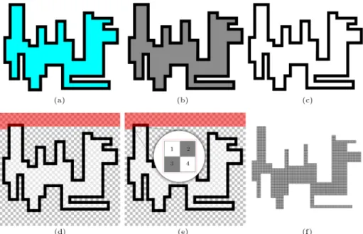
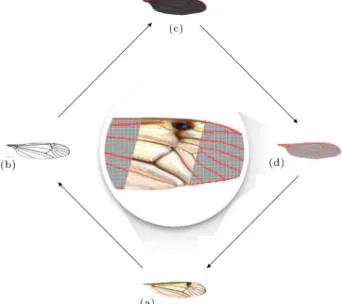
Consider the image shown in Figure 1(a) as an input image. The process of 2D modelling is started by converting the image to greyscale colour mode by using \rgb2gray" function of Matlab through an automated process (Figure 1(b)). This greyscale image is then transformed to a binary (black and white) format (Figure 1(c)) by dening a contrast ratio between 0 and 1. The next step is to extract the boundary of the object in the image. For this purpose, the program checks all the rows of the corresponding matrix of the image pixel by pixel, starting with the rst row to nd any existing black pixels. If there is no black pixel, it checks the next row (Figure 1(d)).
When a black pixel is detected, the modelling process continues by identifying the next black pixel in the row. The rst white pixel between them serves
Figure 1. The main steps of 2D modelling process of a schematic structure made of one material: (a) Input image; (b) the input image in greyscale; (c) the greyscale image after contrast enhancement; (d) searching for nding white pixels inside the boundary of the object; (e) rst element of the model; and (f) developed FE model of the input image.
as the modelling base. But, it should be checked whether this white pixel is located inside the object or not. The simplest way is to check all four sides of the white pixel in order to nd out if it is surrounded by any black pixels or not. If the mentioned pixel is surrounded by black pixels in all the four sides, then it is in the boundary of the object. This white pixel serves as the rst point of the rst rectangular element.
The next pixel is investigated in the same manner. If it satises the criterion, as the previous pixel, it is considered as the second point of the element. In order to form a square element, two more white pixels are required. Therefore, in the next step, the program analyses the condition of the pixels below the rst and the second ones. In other words, four adjacent white pixels inside the object dene a square element (Figure 1(e)). The coordinates of the pixels that dene this element are saved in a text le that is written in ANSYS Parametric Design Language (APDL) and can be readily imported into ANSYS. This process is continued until a meshed model of the object is developed (Figure 1(f)).
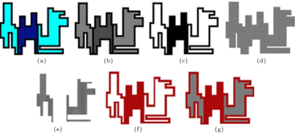
In some cases, as shown in Figure 2(a), the structure under investigation may be composed of two dierent materials. Hence, it is necessary to distinguish between the dierent components. In such cases, the program takes another approach. After pre-processing steps (see Figure 2(b) and (c)), the entire object is meshed by a specic mesh size (Figure 2(d)). In the second step, the program develops an FE model of the areas of the image with white colour (Figure 2(e)). After removing the overlapped areas, an FE model of the other part of the object with black colour is obtained (Figure 2(f)). In this manner, both parts of the structure are modelled separately (Figure 2(g)).
The program is also able to check the image with a user-dened step instead of checking all pixels one by one. Although it causes an increase in the mesh size and may aect the accuracy of the results, it plays an important role in reducing the cost of run-time. 2.2. Three-dimensional modelling
Many biological materials in nature comprise com-plex corrugated patterns. It is assumed that the corrugations have signicant role in improving their mechanical behaviour and biological performances. In order to investigate such eects, in a numerical manner, these corrugations must be included in their mod-els. 3D modelling of such structures requires detailed knowledge about the quality of the corrugations. Such data needs to be provided in an additional image. The image must present the areas with relatively higher heights in black and grey colours. The intensity of the grey colour at each point represents the relative height of that point compared to the others. In this regard, the maximum and the minimum heights are shown with the black and white colours, respec-tively.
The main and the additional images are analysed simultaneously by the program. Whenever in the modelling process the program hits a black pixel, the corresponding height value is given to it automatically. The value of the height corresponding to black pixels (maximum height) is dened by the user. The height of each individual pixel with grey colour is set as a proportion of this dened value. Due to the relative dierences between the colours, this method, in some cases, may cause abrupt local height changes on the surface of the model. In order to prevent this prob-lem, the following formula is used to make a smooth transition between the maximum and minimum height values:
Figure 2. The main steps of 2D modelling process of a schematic structure made of two dierent materials: (a) Input image; (b) the input image in greyscale; (c) the greyscale image after contrast enhancement; (d) FE model of the whole structure as one material; (e) FE model of white sections; (f) FE model of black section that is obtained by removing the overlapped areas of the models in (d) and (e); and (g) FE model of the structure in the input image that is obtained by joining the FE models in (e) and (f).
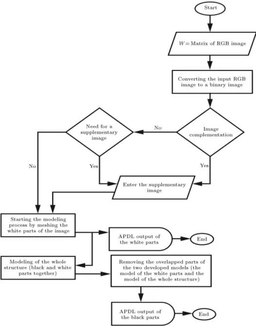
Figure 3. A owchart summarizing the whole modelling technique.
Hi;j(k)= 8 > > > > > > > > > > > > > > < > > > > > > > > > > > > > > :
Hi;j(k 1);
colour of pixel = black
10 Hi;j(k 1)+
i+3
X
a=i+1
Ha;j(k 1)+
i 1
X
a=i 3
Ha;j(k)
+
j+3
X
b=j+1
Hi;b(k 1)+
j 1
X
b=j 3
Hi;b(k) !
221 ; colour of pixel 6= black
where i and j represent the row and column indices of the pixel, respectively; H is the height of the pixel in the range of 0 to 1; k is the iteration number and is dened by the user. Increasing the value of k provides a smoother transition between dierent colours, and
vice versa. By using the above equation, the height of the black pixels remains the same, but the other pixels experience a small change in their heights. Figure 3 shows a owchart describing the main stages of the described modelling technique.
3. Results and discussions
In this section, four examples are presented to demon-strate the validity and feasibility of the proposed method. Each example gives a special case and its specic details. The rst three examples describe 2D modelling of two tree leaves (Morus alba and Platanus orientalis) and a crane-y wing (Nephrotoma cornicina). The 3D modelling of a dragony wing (Orthetrum sabina) is presented in the last example.
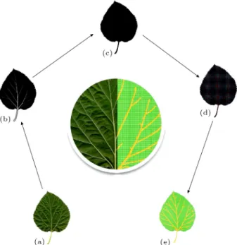
Figure 4. Comparison between Morus alba leaf and its developed FE model: (a) Input image; (b) and (c) generated black and white images by the code; (d) developed model in Matlab; and (e) leaf model in ANSYS environment.
3.1. Example 1
Figure 4(a) shows an image of M. alba leaf. As men-tioned in the previous section, in such cases that the object is made of more than one material, the program generates two black and white images of the given input image (Figure 4(b) and (c)). The obtained images are used to develop two FE models: one representing both materials as one and the other including only one of them. By removing the overlapped areas, a model of the second part of the object is constructed. In this way, FE models of both leaf veins and blades are developed separately and then combined in an integrated model (Figure 4(d)).
Figure 4(e) illustrates the model of the leaf in ANSYS environment. Veins and blades are shown with orange and green colours, respectively. As seen in the gure, the program is able to successfully create the teeth-like margin of the leaf. Comparison of the nal FE model with the input image of the leaf reveals a very good apparent agreement between them (see the central part of Figure 4). Both veins and blades are exactly modelled in their proper locations. The developed model is shown at increasing magnications in Figure 5, representing the detailed characteristics of the model and its meshed construction.
3.2. Example 2
A P. orientalis leaf is displayed in Figure 6(a). As previously mentioned, one of the rst steps in the modelling process is to identify the pixels inside the object. For this purpose, the program checks all four
Figure 5. Magnied views of the FE model of Morus alba leaf.
Figure 6. Comparison between Platanus orientalis leaf and its developed FE model: (a) Input image; (b) generated black and white image by the code; (c) black and white image provided by the user; (d) developed model in Matlab; and (e) leaf model in ANSYS environment.
sides of a single white pixel to nd any black ones. If the pixel under consideration is surrounded by black pixels in all four sides, then it is located in the boundary of the object and is considered as a part of it. Referring to Figure 6(b), it can be seen that there are some points in notches between the lobes of the leaf with the mentioned condition. In other words, there are some white pixels in the regions between the lobes that are surrounded by black pixels and do not belong to the leaf. These regions are shown with red colour.
In order to identify these regions, the program follows a dierent approach. In such situations, the user must provide a supplementary image. The image must include all regions that seem to be appearing in the model, in black colour (Figure 6(c)). This image is employed to detect the boundary of the object and the program only analyses the nodes inside this boundary. The modelling process is completely the same as the one described in the previous section. The developed models in Matlab and ANSYS are shown in Figure 6(d) and (e), respectively. As illustrated in the gure, there is a very good consistency between the leaf and its FE model. All the veins and blades are satisfactorily modelled and they are closely matched with the input image.
Figure 7. Comparison between Nephrotoma cornicina cornicina wing and its developed FE model: (a) Input image; (b) generated black and white image by the code; (c) developed model in Matlab; and (d) wing model in ANSYS environment.
3.3. Example 3
Many insect wings reveal complex structures composed of a network of veins and membranes [31-33]. The veins and membranes exhibit dierent material properties, and therefore need to be modelled as dierent materi-als. Numerical modelling of such biological structures is a dicult and time-consuming process [34].
A crane-y wing (N. cornicina) is shown in Figure 7(a). After conversion to a black and white image (Figure 7(b)), the program uses the obtained image to develop an FE model of the wing in Matlab (Figure 7(c)). Figure 7(c) represents this model in red (as veins) and dark grey (as membranes) colours. The developed nal model in ANSYS environment is demonstrated in Figure 7(d). As seen in the gure, the model provides a reasonable representation of the shape and appearance features, including the overall size and position of the membranes and the venation pattern of the insect wing (see the image in the middle of Figure 7).
3.4. Example 4
Previous studies indicated that dragony wings form a corrugated pattern [35]. It is estimated that the corrugations play an important role in improving the ight performance of dragonies [36,37]. Creating a 3D model containing the wing corrugations gives the opportunity to study the qualitative eects of these structural parameters. But, developing a comprehen-sive numerical model of the insect wings is still a great challenge for researchers [33,38-40].
Figure 8(a) shows the hindwing of an O. sabina. The cross sections of the wing were obtained by
embed-Figure 8. Comparison between Orthetrum sabina wing and its developed FE model: (a) Input image; (b) generated black and white image by the code; (c) 2D FE model of the wing; (d) areas with maximum heights; and (e) 3D FE model of the wing.
ding the wing in epoxy resin and then cutting it into ten segments. Each segment was carefully observed under an optical microscope to extract the cross sections of the wing along its length. Figure 8(d) represents the data from these measurements. In this gure, the nodes with the maximum heights are displayed with the black and grey colours. The nodes with higher heights are represented by darker grey colours. Figure 8(d), together with Figure 8(b) that shows the insect wing in binary format, is directly used by the program to develop 2D and 3D planar FE models of the insect wing. Figure 8(c) shows the developed 2D model of the wing in red and dark grey colours, which are used to display the wing veins and membranes, respectively. As illustrated in this gure and in the central part of Figure 8, the model is in a very good accordance with the input image. All veins and membranes are thoroughly modelled, especially the small ones near the wing tip. The developed 3D model of the wing is presented in Figures 8(e). The height and location of the corrugations reasonably match the data given in Figure 8(d).
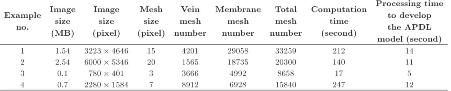
The computation process of the presented exam-ples was performed using a personal computer (Core i7-4510U CPU running at 2.0 GHz, 8GB RAM). The computation time for each individual example, detailed information of the input images, and the developed models are listed in Table 1.
In this article, we have focused on the FE modelling (and not FE analysis) of a few biological structures. Indeed, based on the fact that except for the accuracy of the model, there are many other parameters that can aect the results of an FE analysis,
Table 1. Information of input images, developed models, and processing times of the presented examples. Example
no.
Image size (MB)
Image size (pixel)
Mesh size (pixel)
Vein mesh number
Membrane mesh number
Total mesh number
Computation time (second)
Processing time to develop the APDL model (second)
1 1.54 3223 4646 15 4201 29058 33259 212 14
2 2.54 6000 5346 20 1565 18735 20300 140 11
3 0.1 780 401 3 3666 4992 8658 17 5
4 0.7 2280 1584 7 8912 6928 15840 247 12
performing a numerical simulation is out of the scope of this research. However, for more validation studies, the authors refer the readers to their recently published article [4]. Further research will focus on improving the method for developing numerical models of the structures consisting of more than two materials as well as unstructured mesh generation.
4. Conclusion
This paper was devoted to describing a simple mod-elling technique, which was suitable for materials with complex shapes and geometries; it is specically ad-vised for numerical modelling of planar biological ma-terials. The proposed method was applied to develop FE models of two tree leaves and two insect wings. Comparison of the overall shapes of the developed models and the input images revealed a good agreement between them.
The main advantages of the presented method are as follows:
1. This method is very simple and it is a powerful tool, which is potentially able to develop realistic models of complex geometries. The method can be readily applied to develop numerical models of any other articial and biological planar structures made of one or two materials. The required input for this method is one and in some cases two images;
2. The output of the program is a text le that can be easily imported into a commercial software package such as ANSYS;
3. The computation time of the method is suciently short (a few minutes), even when the input image contains a complex geometry;
4. There is no need for a high-resolution image. The method can be potentially applied to an image with a low quality;
5. Both 2D and 3D planar modelling approaches are available in this method.
Conicts of interest statement
The authors declare there are no conicts of interest to disclose.
Acknowledgements
This study was nancially supported by German Academic Exchange Service (DAAD) to HR (Grant number: 91524738-57048249). The authors would like to thank Prof. Michael S. Engel (Division of Entomology, University of Kansas) and Dr. Pjotr Oosterbroek (Zoological Museum, University of Am-sterdam) for their help in identifying the Nephrotoma. They like to give special thanks to Dr. Mansour Afshar-Mohammadian (Department of Biology, University of Guilan) for determining the species of trees. The authors are also very grateful to Mr. Sadegh Maghsoodi (Department of Computer Engineering, Ahrar Insti-tute of Technology and Higher Education), Mr. Hamid Reza Fallah-Haghmohammadi, Mr. Arash Safari, Ms. Sajedeh Vahdani, Ms. Leila Mottaghi and Mr. Hojjat Mansourpour for their assistance during the prepara-tion of the manuscript.
References
1. Dirks, J.H., Parle, E. and Taylor, D. \Fatigue of insect cuticle", J. Exp. Biol., 216(10), pp. 1924-1927 (2013). 2. Fratzl, P. \Biomimetic materials research: What can we really learn from nature's structural materials?", J. R. Soc. Interface., 4(15), pp. 637-642 (2007).
3. Rajabi, H., Darvizeh, A., Shaei, A., Eshghi, S. and Khaheshi, A. \Experimental and numerical investiga-tions of Otala lactea's shell-I. Quasi-static analysis", J. Mech. Behav. Biomed. Mater., 32, pp. 8-16 (2014). 4. Rajabi, H., Darvizeh, A., Shaei, A., Taylor, D. and Dirks, J.H. \Numerical investigation of insect wing fracture behaviour", J. Biomech., 48(1), pp. 89-94 (2015).
5. Meyers, M.A., Chen, P.Y., Lin, A.Y.M. and Seki, Y. \Biological materials: structure and mechanical properties", Prog. Mater. Sci., 53(1), pp. 1-206 (2008). 6. Barthelat, F. \Biomimetics for next generation ma-terials", Philos. Trans. A Math. Phys. Eng. Sci., 365(1861), pp. 2907-2919 (2007).
7. Bhushan, B. \Biomimetics: Lessons from nature - an overview", Philos. Trans. A Math. Phys. Eng. Sci., 367(1893), pp. 1445-1486 (2009).
8. Gorb, S.N. \Biological attachment devices: exploring nature's diversity for biomimetics", Philos. Trans. A Math. Phys. Eng. Sci., 366(1870), pp. 1557-1574 (2008).
9. Gorb, S.N., Sinha, M., Peressadko, A., Daltorio, K.A. and Quinn, R.D. \Insects did it rst: a micropatterned adhesive tape for robotic applications", Bioinspir. Biomim., 2(4), S117 (2007).
10. Huebsch, N. and Mooney, D.J. \Inspiration and ap-plication in the evolution of biomaterials", Nature, 462(7272), pp. 426-432 (2009).
11. Suli, E., Finite Element Methods for Partial Dier-ential Equations, University of Oxford, Oxford, UK (2002).
12. Alavinia, A., Fallahnezhad, K., Badnava, H. and Farhoudi, H.R. \Eects of buckling initiators on me-chanical behavior of thin-walled square tubes sub-jected to oblique loading", Thin Wall. Struct., 59, pp. 87-96 (2012).
13. Chandrupatla, T.R., Belegundu, A.D., Ramesh, T. and Ray, C. Introduction to Finite Elements in En-gineering, 2nd Edn., Prentice-Hall, Englewood Clis, US (1997).
14. Cook, R.D., Finite Element Modeling for Stress Anal-ysis, John Wiley & Sons Inc., New York, US (1994). 15. Fallahnezhad, K., Steele, A. and Oskouei, R.H.
\Fail-ure mode analysis of aluminum alloy 2024-T3 in double-lap bolted joints with single and double fasten-ers: A numerical and experimental study", Materials, 8(6), pp. 3195-3209 (2015).
16. Huebner, K.H., Dewhirst, D.L., Smith, D.E. and By-rom, T.G., The Finite Element Method for Engineers, John Wiley & Sons Inc., New York, US (2008). 17. Taber, C.S. and Timpone, R.J., Computational
Mod-elling, Sage Publication, London, UK (1996).
18. White, R.E., Computational Mathematics: Models, Methods, and Analysis with MATLAB and MPI, CRC Press, Boca Raton, US (2003).
19. Bryant, R.E., Cheng, K.T., Kahng, A.B., Keutzer, K., Maly, W., Newton, R. and Sangiovanni-Vincentelli, A. \Limitations and challenges of computer-aided design technology for CMOS VLSI", Proceed. of the IEEE, 89(3), pp. 341-365 (2001).
20. Sadowski, T. and Liebich, R. \Hexahedral Meshing of complex and invalid CAD Geometries", In 16th Int. Meshing Roundtable, Seattle (2007).
21. Darvizeh, A., Ansari, R., Momen, A. and Rajabi, H. \Experimental and numerical studies of the mechanical behavior of mollusk shells", In Bi-Annual Int. Conf. on Exp. Solid Mech., Tehran (2014).
22. Faghih Shojaei, M., Mohammadi, V., Rajabi, H. and Darvizeh, A. \Experimental analysis and numerical modeling of mollusk shells as a three dimensional
integrated volume", J. Mech. Behav. Biomed. Mater., 16, pp. 38-54 (2012).
23. Mortenson, M.E., Geometric Modelling, John Wiley & Sons Inc., New York, US (1997).
24. Bazan, C. and Blomgren, P. \Adaptive nite element method for image processing", In Proceed. of COMSOL Multiphysic. Conf., Boston (2005).
25. Chen, S., Yue, Z.Q. and Tham, L.G. \Digital image-based numerical modeling method for prediction of inhomogeneous rock failure", Int. J. Rock Mech. Min. Sci., 41(6), pp. 939-957 (2004).
26. Razmjoo, A. \Application of image processing and nite element analysis in modeling chloride diusion in concrete", Doctoral Dissertations, Clemson University (2014).
27. Yue, Z.Q., Chen, S. and Tham, L.G. \Finite element modeling of geomaterials using digital image process-ing", Comput. Geotech., 30(5), pp. 375-397 (2003). 28. Sarti, A., Gori, R. and Lamberti, C. \A physically
based model to simulate maxillo-facial surgery from 3D CT images", Future Gener. Comp. Sys., 15(2), pp. 217-221 (1999).
29. Newitt, D.C., Van Rietbergen, B. and Majumdar, S. \Processing and analysis of in vivo high-resolution MR images of trabecular bone for longitudinal stud-ies: reproducibility of structural measures and micro-nite element analysis derived mechanical properties", Osteoporos. Int., 13(4), pp. 278-287 (2002).
30. Samani, A., Bishop, J., Yae, M.J. and Plewes, D.B. \Biomechanical 3D nite element modeling of the human breast using MRI data", IEEE Trans. Med. Imaging, 20(4), pp. 271-279 (2001).
31. Darvizeh, A., Rajabi, H., Khaheshi, A., Sobhani, M.K. and Etedadi, J. \Investigation of bee wing composite structure: A scanning electron microscopy study and numerical analysis", In Int. Bionic Eng. Conf., Boston (2011).
32. Dirks, J.H. and Taylor, D. \Veins improve fracture toughness of insect wings", PLoS ONE, 7(8), e43411 (2012).
33. Rajabi, H., Moghadami, M. and Darvizeh, A. \In-vestigation of microstructure, natural frequencies and vibration modes of dragony wing", J. Bionic Eng., 8(2), pp. 165-173 (2011).
34. Darvizeh, M., Darvizeh, A., Rajabi, H. and Rezaei, A. \Free vibration analysis of dragony wings using nite element method", Int., J. Multiphys., 3(1), pp. 101-110 (2009).
35. Rajabi, H. and Darvizeh, A. \Experimental investiga-tions of the functional morphology of dragony wings", Chinese Phys. B, 22(8), 088702 (2013).
36. Kim, W.K., Ko, J.H., Park, H.C. and Byun, D. \Eects of corrugation of the dragony wing on gliding performance", J. Theor. Biol., 260(4), pp. 523-530 (2009).
37. Sunada, S., Zeng, L. and Kawachi, K. \The rela-tionship between dragony wing structure and tor-sional deformation", J. Theor. Biol., 193(1), pp. 39-45 (1998).
38. Darvizeh, A., Rajabi, H. and Khaheshi, A. \Biome-chanical aspects of dragony wing composite struc-ture", In Int. Bionic Eng. Conf., Boston (2011). 39. Jongerius, S.R. and Lentink, D. \Structural analysis of
a dragony wing", Exp. Mech., 50(9), pp. 1323-1334 (2010).
40. Ren, H.H., Wang, X.S., Chen, Y.L. and Li, X.D. \Biomechanical behaviors of dragony wing: relation-ship between conguration and deformation", Chinese Phys. B, 21(3), 034501 (2012).
Biographies
Shahab Eshghi received his BSc degree in Mechanical Engineering, in 2013, from University of Guilan, Iran, where he is currently a master student. He is working on a new method for modelling of the structures with complex geometries by using digital image processing technique. His research interests consist of biomechan-ics, nite element modelling, optimisation, and image processing.
Hamed Rajabi was among the top 1% of 399321 participants in Iran's national entrance examination of universities in 2003. He received his MS and PhD degrees in Mechanical Engineering from University of Guilan, Iran, in 2007 and 2010, respectively. Af-ter graduation, in 2010, he worked as the Acting Head of the Department of Mechanical Engineer-ing at the Ahrar Institute of Technology & Higher Education. The \Biomimetic Engineering Group" (www.biomimeticslab.ir) was established by him and Prof. Darvizeh in 2011. His scientic research in this group enabled him to publish more than 40 journal and conference articles. He further contributed as reviewer in several scientic journals including Jour-nal of Bionic Engineering. In 2014, he received a scholarship from the German Academic Exchange Ser-vice (DAAD) to join the Functional Morphology and Biomechanics Institute at Kiel University, Germany. His major areas of study are biomimetics, biomechanics of insect ight, mechanics of biological tissues, and shape optimisation and sustainability in engineering design.
Abolfazl Darvizeh received his MSc and PhD degrees in Mechanical Engineering from University of Manch-ester, Institute of Science and Technology (UMIST), UK, in 1979 and 1982, respectively. He was selected as a Distinguished Professor of Iran by the Ministry of Science, Research, and Technology, in 1996, and as a Distinguished Professor in Mechanical Engineering by the Iranian Society of Mechanical Engineering (ISME), in 2006. He is author of 16 text books and more than 300 journal and conference articles. His teaching and research interests include biomimet-ics, impact mechanbiomimet-ics, and high energy rate forming processes. The \Biomimetics Engineering Group" (www.biomimeticslab.ir) was established by him and Mr. Hamed Rajabi, in 2011.
Vahid Nooraeefar received his BSc and MSc degrees in Mechanical Engineering in 2006 and 2010, respec-tively, from University of Guilan, Iran. He is currently a PhD student at University of Guilan. His research interests are biomimetics, optimisation, and genetic programming.
Ali Shaei graduated with master degree in the eld of Mechanical Engineering from University of Guilan, Iran, in 2014. He has worked with the \Biomimetics Engineering Group" since 2012. He is an expert in using nite element software packages such as ANSYS and ABAQUS. His goal is to discover the design complexities in biological structures and to apply the obtained knowledge in engineering structures.
Tohid Mirzababaie Mosto is a PhD student at University of Guilan, Iran. He received his Bachelor and Master of Science in Mechanical Engineering from University of Guilan. His research interests are metal forming, impact mechanics, gas detonation, and blast dynamics.
Mona Monsef received her BSc in Mechanical Engi-neering from University of Guilan in 2015. After grad-uation, she joined the University of New Hampshire, USA, to complete her PhD in Solid Mechanics. She has started working with \Biomimetic Engineering Group" since 2013. She is highly interested in bioinspired engi-neering and understanding of the mechanical behaviour of biological structures.