Control Strategy for Three Phase Shunt Active Power Filter with
Minimum Current Measurements
1
Y.Kusuma Latha, 2Ch.Saibabu, 3Y.P.Obulesh
1.3
Department of EEE, Lakireddy Balireddy College of Engineering (Autonomous), Mylavaram-521230, A.P, India
2
Department of Electrical Engg, University College of Engineering (Autonomous), JNTUk, Kakinada, A.P, India e-mail: [email protected], [email protected], [email protected]
Abstract
The active power filter has been proved to be an effective method to mitigate harmonic currents generated by nonlinear loads as well as to compensate reactive power. The methods of harmonic current detection play a crucial part in the performance of active power filter (APF). This paper presents a new control strategy in which two shunt active power filter configurations are developed in order to define new simple control algorithm which requires minimum number of current measurements. The effectiveness of the proposed control strategies are demonstrated through results. The proposed systems are implemented with MATLAB/SIMULINK. The simulation results are presented for two control strategies and comparison is made among them.
Keywords: Harmonics, Active power filter, current sensors, power qualityinprovement
1. Introduction
The increasing use of solid-state power-conversion equipment (rectifiers,inverters, cycloconverters) and other power electronic-type devices (voltage controllers, motor-speed controllers) on distribution systems is causing utilities to become much more concerned about voltage and current harmonic levels[1,2]. The nonlinear characteristic of the power semiconductors results in serious harmonics and reactive power pollution in power system[3.4]. The effective methods for harmonic suppression and reactive power compensation are more and more needed. The Passive Power Filter (PPF) is a traditional way for harmonic suppression, which is composed of power capacitor, power inductance and resistance. PPF has been regarded as the main approach in the field based on its simple architecture, little maintenance and well-developed design. But there are several disadvantages existing in PPF:1) filtering characteristic depends on the impedance of the power supply;2) the impedance characteristic is deteriorated with the frequency reduce to below the lowest resonance frequency;3) PPF can not filter the non-characteristic harmonics entirely; 4) it’s possible to result in current resonance. Active power filters are used to eliminate harmonic currents as well as to compensate for reactive power [5,6]. Principally, the active power filter operates by detecting harmonic current to calculate the amount of the compensating current needed for feeding back to the power system in the opposite direction of the harmonic current[7,8].
In the conventional p-q theory based control approach for the shunt APF, the compensation current references are generated based on the measurement of load currents and the current feedback from the shunt APF output is also required and therefore, minimum four current sensors are desired in a balanced system[9,10]. In this paper, in order to simplify the control scheme for the three phase sunt active power filter, two types of configurations for are developed based on single current measurement. One control scheme based on measurement of load current only, and other control scheme based on measurement of source current only.
2. Proposed control startegies
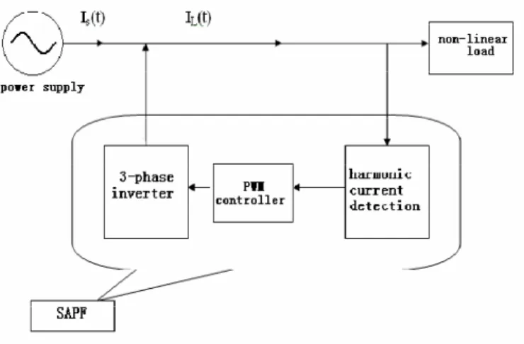
Basic principle of shunt active power filter is showed in Fig.1. Shunt active power filter is mainly composed of harmonic current detecting circuit and compensation current generationcircuit and is parallel connected with thenon-linear load. Its working procedure is as following: firstly the current of the load iL(t) is detected, and its
harmonic component is then calculated by the harmonic current detecting circuit. The inverter is controlled to output the compensation current whose polarities are inversed with the harmonic currents. According to the formula for power line current calculation is(t) = iL(t)+ic(t) = iL(t)-iLh(t), the fundamental frequency component of power line
current is left only. If the reactive power compensation is demanded additionally, the only procedure to add is to compute the reactive power component together with the calculation of harmonic component. Consequently, the unity power factor can be realized.
In the conventional p-q theory based control approach for the shunt APF, the compensation current references are generated based on the measurement of load currents and the current feedback from the shunt APF output is also required and therefore, minimum four current sensors are desired in a balanced system. In order to simplify the control scheme, two types of control techniques are developed for shunt active power
filter based on single current measurement. One control scheme needs only measurement of load current, and other control scheme needs only measurement of source current.
Fig. 1 Shuntactive power filter
2.1 Active Power Filter with Load Current Detection
Active power filter with load current detection only requires load current, source voltage and capacitor voltage. The control system acts in order to perform an indirect regulation of source currents, which must be sinusoidal and in phase with the corresponding line to neutral voltages. Here indirect regulation of the source current is achieved by introducing a closed loop control of the “filter flux”, defined as the time integral of the filter voltage [6]. The block diagram of shunt active power filter with load current measurement is shown in Fig 2.
Fig.2 A.P.F with load current detection
The voltage equation for the shunt active power filter is given as Vୗ= V+ L
ୢ୧ౙ
The integration of equation (1) leads to the following “flux equation”. φ∗
=φୗ− Li∗ୡ
(2) Where φ∗
is the reference “filter flux” and φୗ is the actual “source flux”. The r eference filter current is given by
iେ∗= Iୗ∗− I (3) Where IL is the measured load current and IS* is the reference source current. IS* is obtained by the equations
iୱୟ∗ሺtሻ= I
ୱ୫sin (wt)
iୱୠ∗ሺtሻ= Iୱ୫sin (wt − 120) (4)
iୱୡ∗ሺtሻ= Iୱ୫sin (wt + 120)
and IL is directly measured by current sensors. For balanced load condition two current sensors are used for
measuring load current. Equation (2) is used for calculating reference flux ,φ∗
. The actual value of φୗ is obtained by integrating the output filter voltage, which can be determined on the basis of the dc voltage Vc and the
inverter switch states SA , SB , SC .
v= ଶ
ଷVେ(S+ Se ୨మయπ
+ Se୨ రπ
య) (5)
In this way, the non idealities of voltage source inverter (switching voltage drop and dead times) are neglected leading to steady state errors but avoiding the use of additional wide bandwidth voltage transducers to sense the voltage source inverter output voltage. The difference between reference filter flux and actual filter flux is given to the PWM controller. PWM controller generates firing pulses to control voltage source inverter. Current controlled voltage source inverter is used to inject a compensating current in to the system to relieve the supply from harmonic and reactive currents and enhance power quality indices. The shunt active power filter with load and filter current measurement is requires to measure load currents and the current feedback from the shunt active power filter therefore minimum four current sensors are desired in a balanced system. For unbalanced system six current sensors are required. Furthermore, power full microprocessors are necessary for the online evaluation of the harmonic content of the load currents. The shunt active power filter with load current detection only not requires to measure compensation current and source current and the reference source current is generated based on regulation of capacitor voltage by using PI controller. So shunt active power filter with load current detection is low cost and easy to implement.
2.2 Active Power Filter with Source Current Detection
Active power filter with source current detection only measures source current, source voltage and capacitor voltage. The basic compensation principle of a shunt APF is shown in Figure 3. It is controlled to draw/supply a compensating current Ic from/to the system, so that it cancels current harmonics on AC side, and makes the source current in phase with the source voltage. The different waveforms are shown in Fig 3. Curve A is the non-linear load current waveform and curve B is the desired mains current .Curve C shows the compensating current injected by the active filter containing all harmonics, to make mains current sinusoidal.
The voltage equation for the shunt active power filter is given as Vୗ= V+ L
ୢ୧ౙ
ୢ୲ (6) The source current for the shunt active power filter is given as
I௦=ܫ+ܫ (7)
Being the rate of change of the filter current usually higher than that of the load current, equation (6) can be written as
V= Vୗ− L ୢ୧
ୢ୲ (8) For small variations, the time derivatives can be replaced by finite differences and equation (8) can be written as
V= Vୗ−
∆୲∆iୗ (9)
Fig 3. A.P.F with source current detection
Where ∆iS represents the instantaneous source current error and it obtained by the equation (10)
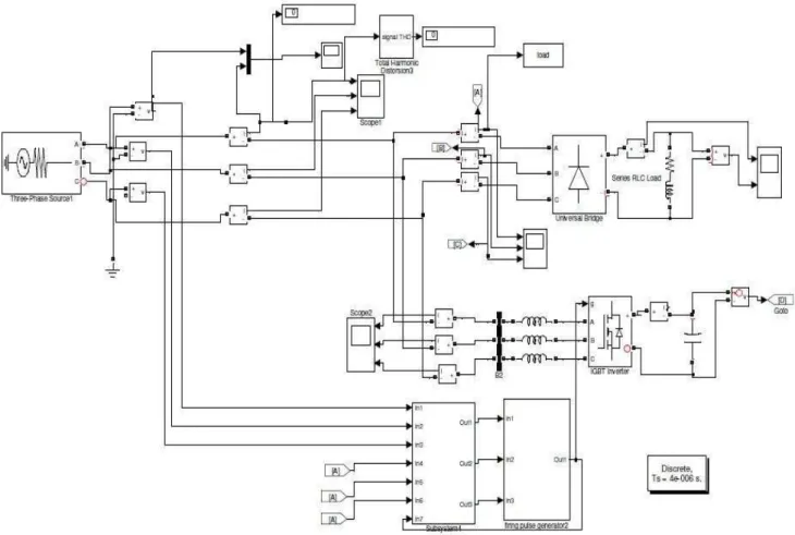
∆iୗ= Iୗ∗− Iୗ (10) Where Iௌ is the measured source current and Iୗ∗is the reference source current. Iୗ∗ is obtained by the equation (10) and Iௌ is directly measured by current sensors. For balanced load condition two current sensors are used for measuring source current. The difference between reference source current and actual source current is given to the hysteresis controller. Hysteresis controller generates firing pulses to control inverter. Current controlled voltage source converter (VSC) is used to inject a compensating current in to the system to relieve the supply from harmonic and reactive currents and enhance power quality indices. In shunt active power filter with load and filter current measurement the compensation current references are generated based on the measurement of load currents and the current feedback from the shunt APF output is also required and therefore, minimum four current sensors are desired in a balanced system. The shunt active power filter with source current detection only not requires to measure compensation current and load current and the reference source current is generated based on regulation of capacitor voltage by using PI controller. So shunt active power filter with source current detection is low cost and easy to implement. Implementation of shunt APF with load current detection is done with Matlab/Simulink and it it is shown in Fig.4
3. Results and Analysis
3.1 Shunt APF with Load current detection
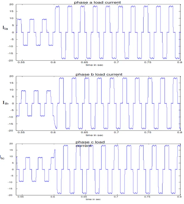
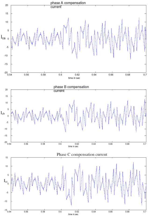
The system shown in Fig 2 is simulated in Matlab/Simulink and the Simulink diagram is shown in Fig.4. The load current containing harmonics is shown in Fig 5.
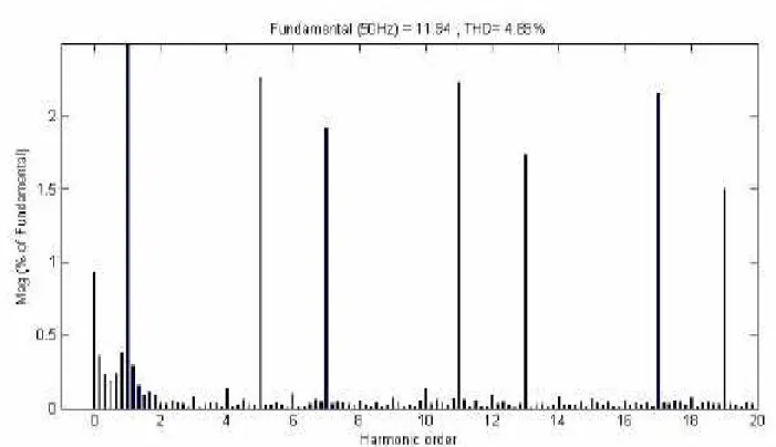
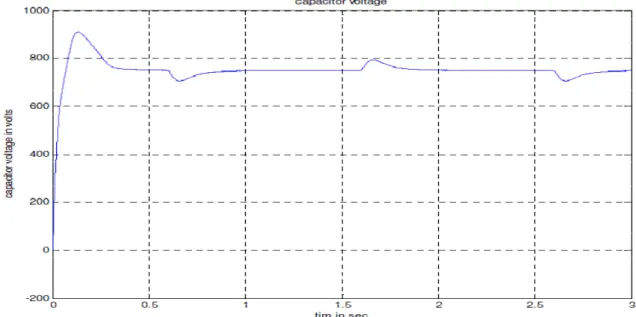
This harmonics are eliminated by injecting compensation currents at PCC. The compensation currents are shown in Fig 6. The compensation currents supply harmonic currents and reactive power demand of the load. Total Harmonic Distortion of the Source current is reduced to 4.89%. Harmonic spectrum for source current after compensation is shown in Fig 7. From Fig 8, it is noticed that the source current is in phase with source voltage and power factor is close to unity. The source current is close to fundamental sinusoid, showing that harmonic current is eliminated from the source current. From Fig 9, it is very clear that the D.C side capacitor voltage is remains constant at its value.
Fig 7 Source current Harmonic Spectrum
Fig 9 capacitor voltage
3.2 Shunt APF with Source Current Detection
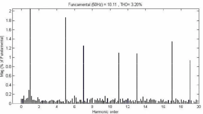
The system shown in Fig 3 is simulated and results are presented. The load current containing harmonics are eliminated by injecting compensation currents at PCC. The compensation currents are shown in Fig 10. The compensation currents supply harmonic currents and reactive power demand of the load. Harmonic spectrum for source current after compensation is shown in Fig 11. The source current Total Harmonic Distortion is reduced to 3.20%.
The source current waveform is close to fundamental sinusoid, showing that harmonic current is eliminated from the source current and also the power factor is close to unity. The source current is in phase with source voltage and is shown Fig 12. The voltage across the D.C side capacitor is also shown in Fig 13.
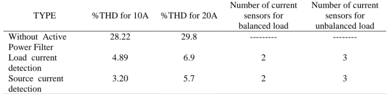
Table 1. Comparison of %THD in source current and required current sensors
4. Conclusion
Control methods of shunt active power filter with minimum measurement requirements are discussed in this chapter. One control scheme is based on measurement of load current only and other control scheme is based on source current only. These Active power filters are used to eliminate harmonic currents as well as to compensate reactive power of the load. The technique is used in this work is easy to implement, and requires less number of current sensors and transformations.
Shunt active power filter with source current detection and shunt APF with load current measurement are investigated and the corresponding results are compared with each other and it is observed that the shunt active power filter with source current measurement exhibits superior performance. The steady state and dynamic responses of the shunt active power filter with source current measurement is better than the APF with load current measurement
TYPE %THD for 10A %THD for 20A
Number of current sensors for balanced load
Number of current sensors for unbalanced load Without Active
Power Filter
28.22 29.8 --- ---
Load current detection
4.89 6.9 2 3
Source current detection
Fig 11 Source current Harmonic Spectrum
Fig 13 Capacitor voltage waveform
References
[1] F.-Z. Peng, G. W. Ott, and D. J. Adams, “Harmonic and reactive power compensation based on the generalized instantaneous reactive power theory for three-phase four-wire systems,” IEEE Trans. Power Electron., vol. 13, no. 6, pp. 1174–1181, Nov. 1998.
[2] H. Akagi, S. Ogasawara, and H. Kim, “The theory of instantaneous power in three-phase four-wire systems: a comprehensive approach,” in Proc. IEEE IAS Annu. Meeting, 1999, pp. 431–439.
[3] Domenico Casadei, Gabriele Grandi,Ugo Reggiani and Claudio Rossi, “Control Methods for Active Power Filters with Minimum Measurement Requirements,” IEEE APEC , Vol. 2, pp.1153-1158, 1999.
[4] B. Singh, K. Al-Haddad, and A. Chandra, “Harmonic elimination, reactive power compensation and load balancing in three-phase, four wire electric distribution systems supplying nonlinear loads,” J. Electric Power Syst. Res.,vol,44, pp. 93– 00, 1998.
[5] Chandra.A, Singh.B, Singh B.N, Al-Haddad.K, "An improved control algorithm of shunt active filter for voltage regulation, harmonic elimination, power-factor correction, and balancing of nonlinear loads," IEEE Trans. Power Electronics,Vol.15, pp. 495-507, May 2000.
[6] M. J. Newman, D. N. Zmood, and D. G. Holmes, “Stationary frame harmonic reference generation for active filters,” IEEE Trans. Ind.Applicat., vol. 38, no. 6, pp. 1591–1599, Nov./Dec. 2002.
[7] H. Karimi, M. Karimi-Ghartemani, R. Iravani and A. Bakhshai, “An adaptive filter for synchronous extraction of harmonics and distortions,” IEEE Trans. Power Delivery, vol. 18, no. 4, pp. 1350-1353, Oct. 2003.
[8] L. H. Tey, P. L. So, and Y. C. Chu, “Improvement of power quality using adaptive shunt filter,” IEEE Trans. Power Del., vol. 20, no. 2,pp. 1558-1568, April 2005.
[9] Lucian Asiminoaei, Frede Blaabjerg, Steffan Hansen, “Evaluation of Harmonic Detection Methods for Active Power Filter Applications,” IEEE Applied Power Electronics Conference and Exposition, Vol. 1, pp.635 – 641, 2005.
[10] Abdelmadjid Chaoui , Jean Paul Gaubert , Fateh Krim ,G rard Champenois “PI Controlled Three-phase Shunt Active Power Filter for Power Quality Improvement”EPE proc.electric power components and systems,volume 35,issue 12 December 2007
Bibliography of authors
Y.Kusuma latha received the B.E (Electrical and Electronics Engineering) degree from Nagarjuna University, Guntur.A.P, India, M.Tech degree from Jawaharlal Nehru Technological University, Anantapur, India in 2000 and 2004. Currently she is working for her Ph.D. She is working as an Associate Professor in the Dept. of Electrical and Electronic Engineering, at Lakireddy Balireddy College of Engineering (Autonomous),Mylavaram. Her areas of interest are Power Quality, Harmonic mitigation techniques, Active power filters and DSP Controllers
Ch. Sai Babu received the B.E from Andhra University (Electrical & Electronics Engineering), M.Tech in Electrical Machines and Industrial Drives from REC, Warangal and PhD in Reliability Studies of HVDC Converters from JNTU, Hyderabad. Currently he is working as a Professor in Dept. of EEE in JNTUCEK, Kakinada. He has published several papers in National and International Journals and Conferences. His area of interest is Power Electronics and Drives, Power System Reliability, HVDC Converter Reliability, Optimization of Electrical Systems and Real Time Energy Management.
Y. P. Obulesh received his B.E degree in Electrical Engineering from Andhra University, Visakhapatnam, India, M.Tech degree from Indian Institute of Technology, Kharagpur, India, in 1996 and 1998.He received his PhD degree from Jawaharlal Nehru Technological University, Hyderabad, in 2006. He got publications in several National and International Journals and Conferences. His areas of interest are simulation and design of power electronics systems, Active filters, Power quality, fuzzy logic and neural network application to power electronics and drives