Sonus – Network Design Group
Sonus Equipment Type Version
SBC 5200
BMC
BIOS
ConnexIP OS
SonusDB
EMA
SBC
SBC 5200
04.00.00R0
V2.4.1
V2.2.0
V02.00.02-R00
sonusdb-V04.00.00-R000
ems-V04.00.00-R000
sbx-V04.00.00-R000
3rd Party Equipment Type Version
Microsoft Lync 2013
Mediation Server
5.0.8308.420
Polycom CX600
Lync Edition
SIP Phone
4.0.7577.4066
Polycom CX500
Lync Edition
SIP Phone
4.0.7577.4100
Cisco Linksys PAP2T
IAD
3.1.15(LS)
Copyright © 2014, Sonus and/or its affiliates. All rights reserved.
This document may not be reproduced or transmitted in any form or by any means, electronic or
mechanical, for any purpose, without the prior written permission of Sonus.
SBC 5000 Series Configuration Guide
with
Lync 2013 for Verizon SIP Trunk
Deployments
Application Notes
Rev. 1.0
Sonus – Network Design Group
2 of 54
Copyright © 2014, Sonus and/or its affiliates. All rights reserved.
Contents
1
Document Overview ... 5
2
Glossary & Acronyms ... 6
3
Introduction ... 8
3.1
Audience ... 8
3.2
Requirements ... 8
3.3
Reference Configuration ... 10
Network Topology ... 10
3.3.1
4
Configuring Sonus SBC 5000 Series ... 11
4.1
SBC Configuration Diagram... 11
4.2
SBC Naming Conventions ... 12
SBC Configuration ... 12
4.2.1
Internal side Configuration ... 12
4.2.2
External side configuration ... 12
4.2.3
4.3
SBC Configuration Workflow ... 13
4.4
Global Configuration ... 14
SIP Max PDU Size ... 14
4.4.1
SIP Domain ... 14
4.4.2
IP Access Control Lists ... 14
4.4.3
UDP Port Range for RTP (media) ... 15
4.4.4
Tone and Announcement Profile ... 15
4.4.5
Tone DSP Resources ... 15
4.4.6
Codec Entry – G.711u ... 15
4.4.7
Codec Entry – G.729 ... 16
4.4.8
4.5
Internal side SBC configuration ... 16
IP Interface Group for Lync 2013 ... 16
4.5.1
4.5.1.1
IP Static Route for Lync 2013 ... 17
4.6
SBC configuration for Lync 2013 Server ... 17
Profile Configuration ... 17
4.6.1
4.6.1.1
Packet Service Profile (PSP)... 17
4.6.1.2
IP Signaling Profile (IPSP) ... 18
Address Context Configuration ... 19
4.6.2
4.6.2.1
DNS Group ... 19
Sonus – Network Design Group
3 of 54
Copyright © 2014, Sonus and/or its affiliates. All rights reserved.
4.6.2.3
SIP Signaling Port ... 20
4.6.2.4
IP Peer using FQDN. ... 20
4.6.2.5
SIP Trunk Group ... 21
4.6.2.1
Path Check Profile ... 21
4.7
SBC configuration for Fax (optional) ... 22
Profile Configuration ... 22
4.7.1
4.7.1.1
Packet Service Profile (PSP)... 22
4.7.1.2
IP Signaling Profile (IPSP) ... 22
Address Context Configuration ... 23
4.7.2
4.7.2.1
Zone ... 23
4.7.2.2
SIP Signaling Port ... 23
4.7.2.3
IP Peer using IP address... 23
4.7.2.4
SIP Trunk Group ... 24
4.8
External side SBC configuration ... 24
IP Interface Group for SIP Signaling ... 24
4.8.1
4.8.1.1
IP Static Route for SIP Signaling ... 25
IP Interface Group for RTP Payload ... 25
4.8.2
4.8.2.1
IP Static Route for RTP Payload ... 25
4.9
SBC configuration for Verizon SIP Trunk ... 26
Profile Configuration ... 26
4.9.1
4.9.1.1
Packet Service Profile (PSP)... 26
4.9.1.2
IP Signaling Profile (IPSP) ... 27
Address Context Configuration ... 27
4.9.2
4.9.2.1
Zone ... 27
4.9.2.2
SIP Signaling Port ... 27
4.9.2.3
IP Peer... 28
4.9.2.4
SIP Trunk Group ... 28
4.9.2.5
Path Check Profile ... 29
4.10
Global Call Routing Configuration ... 29
Lync 2013 Mediation Server Routing ... 29
4.10.1
4.10.1.1
Routing Label ... 30
Verizon SIP Trunk Routing ... 30
4.10.1
4.10.1.1
Routing Label ... 30
Routing ... 31
4.10.2
5
Lync Server 2013 configuration ... 32
Sonus – Network Design Group
4 of 54
Copyright © 2014, Sonus and/or its affiliates. All rights reserved.
5.1
Lync 2013 Configuration Settings ... 32
This section covers the addition of the SBC into the Lync Server. ... 32
5.1.1
This section covers adding the SBC to the Lync Server 2013 routing. ... 36
5.1.2
6
SBC and Lync 2013 Specific Configurations ... 39
6.1
Initial Setup for All Calls ... 39
DM/PM Rules ... 39
6.1.1
10-Digit Dialing ... 39
6.1.2
6.2
Initiating Transfers with REFER ... 39
Call transfer via REFER method – Not Supported ... 39
6.2.1
6.3
Initiating Transfers with Re-INVITE ... 39
Call transfer via Re-Invite method ... 39
6.3.1
6.4
Call Hold... 40
Call Hold via RFC3264 ... 40
6.4.1
7
Appendix A – DM/PM Criteria and Rules ... 41
7.1
DM/PM Criteria ... 41
Lync 2013 to Verizon SIP Trunk number manipulation ... 41
7.1.1
7.1.1.1
DM/PM Criteria – Lync 2013 numbers ... 41
7.1.1.2
DM/PM Criteria – Verizon SIP Trunk numbers ... 42
7.1.1.3
DM/PM Rules – Lync to Verizon mapping ... 43
7.1.1.4
DM/PM Rules – Lync to Verizon mapping ... 44
8
Appendix B – Call routing ... 46
8.1
Call Routing - optional ... 46
International Call - Routing when using DM/PM rules ... 46
8.1.1
8.1.1.1
–International Call - Routing to Verizon Operator Assistance... 46
9
Appendix C – Sip Adaptor Profiles (SMM Rules) ... 47
9.1
SIP Message Manipulation ... 47
Message Manipulation requirements ... 47
9.1.1
9.1.1.1
History-Info Header to Diversion Header mapping SMM ... 47
9.1.1.2
Static From Header SMM ... 47
9.1.1.3
Static P-Asserted Identify Header SMM ... 48
Sonus – Network Design Group
5 of 54
Copyright © 2014, Sonus and/or its affiliates. All rights reserved.
1 Document Overview
These Application Notes describe the configuration steps required for the Sonus Session Border Controller 5000
series (5100, 5110, 5200, 5210) to interoperate with the Lync 2013 Mediation Server and Verizon SIP Trunk.
SBC 5000 series functionality was compliance tested using a SIP trunk to Verizon from an SBC 5200.
The objective of the document is to describe the procedure to be followed during interoperability testing of SBC
5000 series with Verizon.
The interoperability tested was between Polycom Lync Edition clients, Microsoft Lync 2013 Mediation Server,
Sonus SBC 5200, and Verizon SIP Trunk.
For additional information on Sonus SBC 5000 series, visit http://www.sonus.net
For additional information on Microsoft Lync, visit
http://technet.microsoft.com/en-us/lync/fp123621.aspx
For additional information on Polycom Lync Phones, visit
http://www.polycom.com/products-services/products-for-microsoft/conference-phones-microsoft-lync/desktop-phones-microsoft-lync.html
Sonus – Network Design Group
6 of 54
Copyright © 2014, Sonus and/or its affiliates. All rights reserved.
2 Glossary & Acronyms
Term
Definition
1pcc
First party Call Control. All telephony commands executed
directly from the physical handset
3pcc
Third party call control. All telephony commands executed on
behalf of the physical handset by a computer software or
application like SIP Server.
AOC
Advice Of Charge
B2B UA
Back to Back User Agent
CP
Calling Party
CPD
Call Progress Detection
CPE
Customer Premise Equipment – Lync 2013 Mediation Server is
the CPE device in this case.
CTI
Computer Telephony Integration
DNIS
Dialed Number Identification Service
DSI
Sonus component of NBS – Data Stream Integrator
EMS
Sonus component of NBS - Element Management Server
FQDN
Fully Qualified Domain Name
GSX
Gateway Server Exchange
IP
Internet Protocol
IPXC
IP Transfer Connect
IPTF
IP Toll Free
IW
Interaction Workspace
MCP
Media Control Platform
MS
Media Server
NBS
Network Border Switch
PBX
Private Branch Exchange
PSX
Policy Server Exchange
RM
Resource Manager
SDOP
Signaled Digits Out-Pulsed
Sonus – Network Design Group
7 of 54
Copyright © 2014, Sonus and/or its affiliates. All rights reserved.
Term
Definition
SMM
SIP Message Manipulation
TP
Target Party
URS
Universal Routing Server
Sonus – Network Design Group
8 of 54
Copyright © 2014, Sonus and/or its affiliates. All rights reserved.
3 Introduction
This document provides a configuration guide for Sonus SBC 5000 Series (Session Border Controller) when
connecting to a Verizon SIP Trunk and Microsoft Lync 2013 Mediation Server.
The Sonus SBC 5200 is a Session Border Controller that connects disparate SIP trunks, SIP PBXs, and
communication applications within an enterprise. It can also be used as a SIP routing and integration engine.
The Sonus SBC is the point of connection between the Microsoft Lync 2013 Mediation Server and the Verizon
SIP Trunk.
3.1 Audience
This technical document is intended for telecommunication engineers with the purpose of configuring both the
Sonus SBC 5xx0 and aspects of the Microsoft Lync 2013 Mediation Server product. There will be steps that
require navigating the third-party and Sonus SBC Command Line Interface (CLI). Understanding the basic
concepts of IP/Routing and SIP/RTP is also necessary to complete the configuration and for troubleshooting, if
necessary.
This configuration guide is offered as a convenience to Sonus customers. The specifications and information
regarding the product in this guide are subject to change without notice. All statements, information, and
recommendations in this guide are believed to be accurate but are presented without warranty of any kind,
express or implied, and are provided “AS IS”. Users must take full responsibility for the application of the
specifications and information in this guide.
Technical support on SBC 5000 can be obtained through the following:
Phone: (978) 614-8589 or (888) 391-3434 (Toll-free)
Web:
http://sonusnetworks.force.com/PortalLoginPage
3.2 Requirements
The following equipment and software was used for the sample configuration provided:
Sonus Equipment Type Version
SBC 5200
BMC
BIOS
ConnexIP OS
SonusDB
EMA
SBC
SBC 5200
04.00.00R0
V2.4.1
V2.2.0
V02.00.02-R00
sonusdb-V04.00.00-R000
ems-V04.00.00-R000
sbx-V04.00.00-R000
Sonus – Network Design Group
9 of 54
Copyright © 2014, Sonus and/or its affiliates. All rights reserved.
3rd Party Equipment Type Version
Microsoft Lync 2013
Mediation Server
5.0.8308.420
Polycom CX600
Lync Edition
SIP Phone
4.0.7577.4066
Polycom CX500
Lync Edition
SIP Phone
4.0.7577.4100
Sonus – Network Design Group
10 of 54
Copyright © 2014, Sonus and/or its affiliates. All rights reserved.
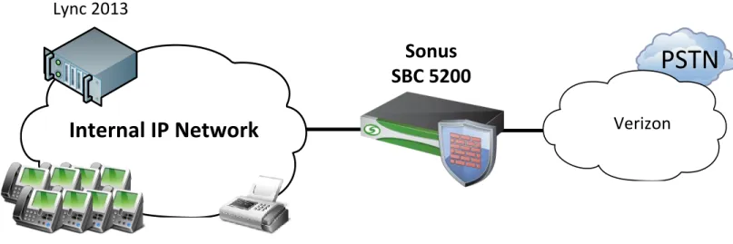
3.3 Reference Configuration
A simulated enterprise site consisting of Polycom CX500 and CX600 Lync Edition SIP Phones serviced through
Microsoft Lync 2013 and Mediation Server. An SBC 5200 Version 4.0.0 R0 was used during testing. SIP Trunks
were used to connect the SBC to Verizon PSTN.
Network Topology
3.3.1
PSTN
Lync 2013
Sonus
SBC 5200
Verizon
Internal IP Network
Figure 1: Network Topology
The figure above represents the equipment used for the integration and certification testing. The SBC 5xx0 is
used to route and facilitate calls between the Lync Mediation Server and the Verizon SIP Trunk.
Sonus – Network Design Group
11 of 54
Copyright © 2014, Sonus and/or its affiliates. All rights reserved.
4 Configuring Sonus SBC 5000 Series
This section describes how to use the Sonus Command Line Interface (CLI) to configure and manage the SBC
5000 Series.
The SBC can equally be configured and managed by the Embedded Management Application (EMA), which is a
Web-based interface management system for the Sonus SBC 5000 Series. However, documentation of the
equivalent configuration steps via EMA is beyond the scope of this guide.
4.1 SBC Configuration Diagram
SIP-LYNC-2013
IN/OUT-SIP-VZ
Internal
Lync 2013
External
IP Interface Group: TRUSTEDZone: TRUSTED
SIP Port: 10.35.180.136:5068
SIP Trunk Group: IN/OUT-SIP-LYNC-2013
FAX
Fax via ATA
IP Interface Group: TRUSTED Zone: TRUSTED
SIP Port: 10.35.137.39:5060 SIP Trunk Group: FAX
IP Interface Group: UNTRUSTED Zone: UNTRUSTED
SIP Port: 63.121.48.43:5060 SIP Trunk Group: IN/OUT-SIP-VZ
63.79.179.178:5060 10.35.180.136:5068
10.35.137.39:5060
SIP over UDP SIP over UDP
SIP over TCP
(optional)
Verizon
Figure 2: SBC 5xx0 SIP Trunk Diagram
The above diagram also shows an optional Fax Trunk Group. Fax machines typically get their own Trunk
Group(s) which allows Fax-specific Packet Service Profile (PSP) and IP Signaling Profile (IPSP) configurations
without affecting non-Fax devices. While this document shows a Fax-specific Trunk Group, it does not have a
Route or Routing Label to use it. Call Routing to a specific Fax Trunk Group is usually done by called/calling
number routing (vs. trunk group routing) which is beyond the scope of this document.
The Fax Trunk Group can share the same SIP signaling interface and Zone on the SBC.
Lync 2013 only supports SIP over TCP (or TLS). The preference to control the SIP transport protocol is
configured in the IP Signaling Profile, which is applied at the Trunk Group level. This allows the proper SIP
signaling transport to be used for both Lync and Fax machine even though they use different transport protocols
with the same SIP signaling interface (SIP Signaling Port) on the SBC 5000.
Sonus – Network Design Group
12 of 54
Copyright © 2014, Sonus and/or its affiliates. All rights reserved.
4.2 SBC Naming Conventions
SBC Configuration
4.2.1
The SBC has both a System Name and a Compute Element (CE) Name (also referred to as a Host or Element
Name) whose differentiation is relative to an High Availability deployment (one SBC active, one SBC standby).
Each SBC server in an HA pair will have its own unique CE Name, while the HA pair will have a single System
Name. Even an SBC deployed in standalone mode will have a separate System Name and CE Name.
To follow Sonus best practice naming conventions, each server’s CE Name will usually have a simple “a/b” suffix
appended to the System Name:
SBC System Name SBC CE Name (active) SBC CE Name (standby)
SBC01 SBC01a SBC01b
Internal side Configuration
4.2.2
Unique address contexts, other than “default”, are only needed when using overlapping IP address space. This
deployment assumes no such overlapping IP space, thus all configurations are in addressContext “default”.
Configuration Entity Lync 2013 FAX (optional) Address Context default default IP Interface Group TRUSTED TRUSTED
Zone TRUSTED TRUSTED
Ingress Trunk Group IN-SIP-LYNC2013 FAX Egress Trunk Group OUT-SIP-LYNC2013 FAX
IP Peer LYNC2013-FQDN LinkSys-PAP2T IP Signaling Profile (IPSP) LYNC-SIP FAX-SIP Packet Service Profile (PSP) LYNC-PSP FAX-PSP
Routing Label OUT-SIP-TO-LYNC2013 N/A DM/PM criteria See Appendix A N/A DM/PM rule See Appendix A N/A
External side configuration
4.2.3
Unique address contexts, other than “default”, are only needed when using overlapping IP address space. This
deployment assumes no such overlapping IP space, thus all configurations are in addressContext “default”.
Sonus – Network Design Group
13 of 54
Copyright © 2014, Sonus and/or its affiliates. All rights reserved.
Address Context Default IP Interface Group UNTRUSTED
Zone UNTRUSTED
Trunk Group IN-SIP-VZ Trunk Group OUT-SIP-VZ
IP Peer VERIZON_DOMESTIC IP Signaling Profile (IPSP) VZ-SIP Packet Service Profile (PSP) VZ-PSP
Routing Label OUT-SIP-TO-VERIZON DM/PM criteria See Appendix A
DM/PM rule See Appendix A
4.3 SBC Configuration Workflow
|---- Global Configuration
|
|----Media Port Range
|
|----Tone and Announcement Profile
|
|----Tone DSP Resources
|
|----Codec Entry
|
|----Digit Manipulation/Parameter Manipulation
|
|---- Internal side Configuration
|
|----IP Interface and IP Interface Group
|
|----IP Static Routes
|---- Verizon Side Configuration
|
|----Configuring Profiles
|
|
|----Packet Service Profile
|
|
|----IP Signaling Profile
|
|----Configuring Address Context
|
|
|----Zone
|
|
|----SIP Signaling Port
|
|
|----IP Peer
|
|
|----SIP Trunkgroup
|
|---- Fax Configuration
|
|----Configuring Profiles
|
|
|----Packet Service Profile
|
|
|----IP Signaling Profile
|
|----Configuring Address Context
|
|
|----Zone
|
|
|----SIP Signaling Port
|
|
|----IP Peer
|
|
|----SIP Trunkgroup
|
Sonus – Network Design Group
14 of 54
Copyright © 2014, Sonus and/or its affiliates. All rights reserved.
|---- External side Configuration
|
|----IP Interface and IP Interface Group
|
|----IP Static Routes
|---- PBX Side Configuration
|
|----Configuring Profiles
|
|
|----Packet Service Profile
|
|
|----IP Signaling Profile
|
|----Configuring Address Context
|
|
|----DNS Group
|
|
|----Zone
|
|
|----SIP Signaling Port
|
|
|----IP Peer
|
|
|----SIP Trunkgroup
|
|---- Global Call Routing Configuration
|
|----Verizon Side Routing
|
|
|----Routing Label
|
|----PBX Side Routing
|
|
|----Routing Label
|
|----Routing
4.4 Global Configuration
SIP Max PDU Size
4.4.1
Increase the Maximum PDU size to accommodate larger SIP packets.
set global signaling sipSigControls maxPduSizeValue pdusize60kb commit
SIP Domain
4.4.2
Configure SIP Domain Name.
set global sipDomain LYNC2013.SONUSNET.COM commit
IP Access Control Lists
4.4.3
Configure IP Access Control list entries. IP Access Control Lists (ACLs) are filters provisioned to protect the SBC
from attacks by blocking IP traffic that may be harmful to the network. ACLs allow users to specify rules to permit
or deny packets into the SBC.
ACLs must be configured on all Test Environment SBC interfaces that are connected to some untrusted network
element. (Usually only those interfaces that connect directly to the internet, as connections that go thru the
Sonus corporate firewall should be protected by that entity's ACL rules.) In any case, applying ACL rules on all
SBC interfaces is a best practice.
Sonus – Network Design Group
15 of 54
Copyright © 2014, Sonus and/or its affiliates. All rights reserved.
set addressContext default ipAccessControlList rule WHITELIST-VZ-IN action accept precedence 22000 protocol udp ipInterfaceGroup UNTRUSTED ipInterface pkt2 sourceIpAddress 63.79.179.178 sourcePort 5109 destinationPort 5060 state enabled
commit
set addressContext default ipAccessControlList rule DENY-ALL-UNTRUSTED action deny precedence 65001 protocol any ipInterfaceGroup UNTRUSTED ipInterface pkt2 state enabled
commit
UDP Port Range for RTP (media)
4.4.4
The Sonus SBC 5000 series defaults to using the UDP port range of 1024-65148 for RTP (media) traffic. Many
enterprise networking devices, including security devices may assume a range of 16384-32767. The following
configuration modifies the SBC to work within that more limited range with no changes to the existing devices.
set system media mediaPortRange baseUdpPort 16384 maxUdpPort 32767 commit
Tone and Announcement Profile
4.4.5
If required SBC 5xx0 can provide a ringback tone.
This is achieved by creating a Tone and Announcement Profile and assigning Tone DSP resources to allow the
SBC to provide local ring back when needed.
set profiles media toneAndAnnouncementProfile DEFAULT_TNA_PROFILE localRingBackTone signalingTonePackageState enable
set profiles media toneAndAnnouncementProfile DEFAULT_TNA_PROFILE localRingBackTone signalingTonePackage DEFAULT
set profiles media toneAndAnnouncementProfile DEFAULT_TNA_PROFILE localRingBackTone makeInbandToneAvailable enable
set profiles media toneAndAnnouncementProfile DEFAULT_TNA_PROFILE localRingBackTone flags useThisLrbtForIngress enable
set profiles media toneAndAnnouncementProfile DEFAULT_TNA_PROFILE localRingBackTone flags useThisLrbtForEgress disable
set profiles media toneAndAnnouncementProfile DEFAULT_TNA_PROFILE localRingBackTone precedence lower set profiles media toneAndAnnouncementProfile DEFAULT_TNA_PROFILE toneAndAnnouncement
announcementPackageState enable commit
Tone DSP Resources
4.4.6
Configure the DSP resources on the SBC for Tone and Announcement support. This configuration only applies if
the SBC has been deployed with DSP resources.
set system mediaProfile compression 90 tone 10 commit
Codec Entry – G.711u
4.4.7
Create a Codec Entry for the G711u codec with DTMF Relay configured for RFC2833, so that DTMF information
will be carried in the audio path as RTP events (e.g. 2833 method).
Parameter Description
Sonus – Network Design Group
16 of 54
Copyright © 2014, Sonus and/or its affiliates. All rights reserved.
g711 Codec selected
20 Packet size in milliseconds
rfc2833 Type of DTMF Relay chosen: carriers DTMF in signaling protocol faxRelay What method to use for FAX handling
set profiles media codecEntry VZ-G711U-20ms codec g711 packetSize 20 set profiles media codecEntry VZ-G711U-20ms dtmf relay rfc2833
set profiles media codecEntry VZ-G711u-20ms fax toneTreatment faxRelay commit
Codec Entry – G.729
4.4.8
Create another Codec Entry for the G729 codec with DTMF Relay configured for RFC2833 so that DTMF
information will be carried in the audio path as RTP events (e.g. 2833 method).
faxRelay What method to use for FAX handling
set profiles media codecEntry VZ-G729-20ms codec g729 packetSize 20 set profiles media codecEntry VZ-G729-20ms dtmf relay rfc2833
set profiles media codecEntry VZ-G729-20ms fax toneTreatment faxRelay commit
4.5 Internal side SBC configuration
IP Interface Group for Lync 2013
4.5.1
The below configuration is for a Sonus 52x0 system using a single port for Internal connectivity (the Sonus
convention is to use Media 2 and Media 3 ports for Internal connectivity). A similar configuration (not shown) for
the Sonus 51x0 system, which only has a total of two Media ports, would use the Media 1 port for Internal
connectivity per Sonus convention. SBC 5000 Media ports do not have dedicated Internal/External roles and,
while recommended, the Sonus convention does not need to be followed. For more information on Media port
deployment options or other network connectivity queries, refer to the
SBC 5000 Network Deployment Guide
or
contact your local Sales team for information regarding the Sonus Network Design professional services
offerings.
Create an IP Interface Group for SIP Signaling and RTP Payload for Lync 2013 and assign interfaces, including
IP addresses.
Parameter Description Parameter Description
VZ-G729-20ms Name of codec entry G729 Codec selected
20 Packet size in milliseconds
Sonus – Network Design Group
17 of 54
Copyright © 2014, Sonus and/or its affiliates. All rights reserved.
default Name of the address context
TRUSTED IP Interface Group name for the internal side of the SBC pkt0 Media interface name for internal side
pkt0 Gigabit Ethernet port used for signaling and media internally 10.35.177.246 IP address for first internal media port
26 IP subnet prefix (subnet mask in CIDR format) LITTLE SBC element name
set addressContext default ipInterfaceGroup TRUSTED
set addressContext default ipInterfaceGroup TRUSTED ipInterface pkt0 ceName LITTLE set addressContext default ipInterfaceGroup TRUSTED ipInterface pkt0 portName pkt0
set addressContext default ipInterfaceGroup TRUSTED ipInterface pkt0 ipAddress 10.35.177.246 prefix 26 set addressContext default ipInterfaceGroup TRUSTED ipInterface pkt0 mode inService state enabled commit
4.5.1.1
IP Static Route for Lync 2013
Create a default route to the subnet’s IP nexthop for the Interface and IP Interface Group.
Parameter Description
default Name of the address context
TRUSTED IP Interface Group name for the internal side of the SBC pkt0 Media interface name for internal side
0.0.0.0 Default route
0 IP subnet prefix (subnet mask in CIDR format) 10.35.177.193 IP Nexthop for subnet
100 Preference
set addressContext default staticRoute 0.0.0.0 0 10.35.177.193 TRUSTED pkt0 preference 100 commit
4.6 SBC configuration for Lync 2013 Server
Profile Configuration
4.6.1
4.6.1.1
Packet Service Profile (PSP)
Create a Packet Service Profile (PSP) for the Lync 2013 SIP trunk with a single codec specified. The PSP will
be specified within the SIP Trunk Group configuration. Microsoft Lync 2013 and Polycom CX500 and CX600
Phones only support the G.711u codec for the purpose of interworking with Verizon SIP Trunks.
Parameter Description
LYNC-PSP Name of the PSP for the Lync 2013
Sonus – Network Design Group
18 of 54
Copyright © 2014, Sonus and/or its affiliates. All rights reserved.
conditional Only transcode if certain conditions are met
g711u Specify transcode codec to use on this (Lync) call leg g711u,g729 Specify transcode codec to use on other (Verizon) call leg heartbeat Disable Silence Insertion Descriptor (SID) packets 0 Silence Factor expected (0=none)
184 ToS Parameter value in IP Header 101 DTMF RTP Payload type
set profiles media packetServiceProfile LYNC-PSP
set profiles media packetServiceProfile LYNC-PSP codec codecEntry1 VZ-G711u-20ms
set profiles media packetServiceProfile LYNC-PSP packetToPacketControl transcode conditional set profiles media packetServiceProfile LYNC-PSP packetToPacketControl codecsAllowedForTranscoding thisLeg g711u otherLeg g711u,g729
set profiles media packetServiceProfile LYNC-PSP silenceInsertionDescriptor heartbeat disable set profiles media packetServiceProfile LYNC-PSP silenceFactor 0 typeOfService 184
set profiles media packetServiceProfile LYNC-PSP preferredRtpPayloadTypeForDtmfRelay 101 set profiles media packetServiceProfile LYNC-PSP silenceFactor 0
set profiles media packetServiceProfile LYNC-PSP typeOfService 184 commit
4.6.1.2
IP Signaling Profile (IPSP)
Create an IP Signaling Profile (IPSP) for the Lync SIP trunk. The IPSP will be specified within the SIP Trunk
Group configuration.
Parameter Description
LYNC-SIP Name of the IPSP for the Lync 2013 Mediation Server sipOnly
tcp Lync 2013 supports TCP transport
set profiles signaling ipSignalingProfile LYNC-SIP
set profiles signaling ipSignalingProfile LYNC-SIP ipProtocolType sipOnly
set profiles signaling ipSignalingProfile LYNC-SIP commonIpAttributes flags includeReasonHeader enable set profiles signaling ipSignalingProfile LYNC-SIP commonIpAttributes flags sendPtimeInSdp enable set profiles signaling ipSignalingProfile LYNC-SIP commonIpAttributes flags sendRtcpPortInSdp enable set profiles signaling ipSignalingProfile LYNC-SIP commonIpAttributes optionTagInRequireHeader suppressReplaceTag enable
set profiles signaling ipSignalingProfile LYNC-SIP commonIpAttributes flags routeUsingRecvdFqdn enable set profiles signaling ipSignalingProfile LYNC-SIP egressIpAttributes numberGlobalizationProfile DEFAULT_IP
set profiles signaling ipSignalingProfile LYNC-SIP egressIpAttributes domainName useZoneLevelDomainNameInContact enable
set profiles signaling ipSignalingProfile LYNC-SIP egressIpAttributes transport type1 tcp
set profiles signaling ipSignalingProfile LYNC-SIP ingressIpAttributes flags sendSdpIn200OkIf18xReliable enable
set profiles signaling ipSignalingProfile LYNC-SIP commonIpAttributes flags publishIPInHoldSDP enable commit
Sonus – Network Design Group
19 of 54
Copyright © 2014, Sonus and/or its affiliates. All rights reserved.
Address Context Configuration
4.6.2
Creation of a unique Zone and SIP Signaling Port for each internal device is not a requirement, however it does
allow for greater conceptual separation and will be used in this document.
4.6.2.1
DNS Group
DNS Groups set DNS objects that may be used for DNS resolution within a particular Zone.
The SBC has the capability to query an external DNS server to resolve hostnames. For scenarios where DNS
servers are not available or accessible, the SBC also has the ability to have IP to hostname mappings
configured locally.
Parameter Description
default Name of the address context nenana Name of the DNS Group
10.35.137.71 IP Address of a DNS Server assigned to this DNS Group mgmtGroup The interface the DNS Group is assigned
LYNC2013 A unique DNS local record ID associated with the DNS Group 10.35.180.136 IP Address of the local record LYNC2013 within the DNS Group fe.lync2013.sonusnet.com The FQDN for the local record LYNC2013
priority DNS resolution priority weighting for the specified local entity IP Address
set addressContext default dnsGroup nenana type mgmt interface mgmtGroup commit
set addressContext default dnsGroup nenana localRecord LYNC2013 hostName fe.lync2013.sonusnet.com order priority state enabled
commit
set addressContext default dnsGroup nenana localRecord LYNC2013 data 1 priority 0 type a ipAddress 10.35.180.136 state enabled
commit
set addressContext default dnsGroup nenana server nenana ipAddress 10.35.137.71 state disabled commit
4.6.2.2
Zone
This Zone groups the set of objects that is used for the communication to the Lync 2013 Server.
Parameter Description
default Name of the address context
TRUSTED Name of Zone for the Lync 2013 Mediation Server 3 A unique numeric identifier (2-2048) for the zone nenana The DNS group associated with this zone lync2013.sonusnet.com The FQDN for this Zone
Sonus – Network Design Group
20 of 54
Copyright © 2014, Sonus and/or its affiliates. All rights reserved.
set addressContext default zone TRUSTED id 3 commit
set addressContext default zone TRUSTED dnsGroup nenana commit
set addressContext default zone TRUSTED dnsGroup nenana domainName lync2013.sonusnet.com commit
4.6.2.3
SIP Signaling Port
A SIP signaling port is a logical address permanently bound to a specific zone and is used to send and
receive SIP call signaling packets. In this case it is bound to the TRUSTED zone and will send and receive
SIP packets for the Lync 2013 Server.
Parameter Description
default Name of the address context TRUSTED Name of Zone for the Lync 2013
TRUSTED IP Interface Group name for the internal side of the SBC sip-tcp Transport protocols allowed for SIP signaling to Lync 2013 10.35.177.247 IPv4 address for the SIP Signaling Address for the SBC 5060 SIP signaling port of SBC
26 DiffServ Code Point value for SIP signaling traffic from SBC
set addressContext default zone TRUSTED sipSigPort 3 ipInterfaceGroup TRUSTED
set addressContext default zone TRUSTED sipSigPort 3 transportProtocolsAllowed sip-tcp set addressContext default zone TRUSTED sipSigPort 3 ipAddressV4 10.35.177.247
set addressContext default zone TRUSTED sipSigPort 3 portNumber 5060 dscpValue 26 set addressContext default zone TRUSTED sipSigPort 3 state enabled mode inService commit
4.6.2.4
IP Peer using FQDN.
Create an IP Peer with the FQDN of the Lync 2013 Mediation Server and assign it to the TRUSTED zone.
The IP Peer entity is used on egress. The ingressIpPrefix parameter in the sipTrunkGroup object is used on
ingress, for determining the applicable SIP Trunk Group.
Parameter Description
Default Name of the address context
TRUSTED Name of Zone for the Lync 2013 Mediation Server LYNC2013-FQDN Name of IP Peer for Lync 2013 Mediation Server fe.lync2013.sonusnet.com DNS FQDN of Lync 2013 Mediation Server
Sonus – Network Design Group
21 of 54
Copyright © 2014, Sonus and/or its affiliates. All rights reserved.
set addressContext default zone TRUSTED ipPeer LYNC2013-FQDN policy sip fqdn fe.lync2013.sonusnet.com commit
set addressContext default zone TRUSTED ipPeer LYNC2013-FQDN policy sip fqdnPort 5068 commit
4.6.2.5
SIP Trunk Group
Create a SIP Trunk group towards the Lync 2013 Mediation Server and assign the corresponding Profiles
configured earlier in this document.
Parameter Description
default Name of the address context
TRUSTED Name of Zone for the Lync 2013 Mediation Server
IN-SIP-LYNC2013 Name of the Ingress SIP Trunk Group from the Lync 2013 Mediation Server
OUT-SIP-LYNC2013 Name of the Egress SIP Trunk Group to the Lync 2013 Mediation Server
TRUSTED IP Interface Group name for the internal side of the SBC 10.35.180.136 IP Address of Lync 2013 Mediation Server
32 IP prefix (subnet mask in CIDR format)
LYNC-PSP Earlier created PSP is applied in the Trunk Group
set addressContext default zone TRUSTED sipTrunkGroup IN-SIP-LYNC2013 media mediaIpInterfaceGroupName TRUSTED
set addressContext default zone TRUSTED sipTrunkGroup IN-SIP-LYNC2013 ingressIpPrefix 10.35.180.136 32 set addressContext default zone TRUSTED sipTrunkGroup IN-SIP-LYNC2013 policy signaling
ipSignalingProfile LYNC-SIP
set addressContext default zone TRUSTED sipTrunkGroup IN-SIP-LYNC2013 policy media packetServiceProfile LYNC-PSP
set addressContext default zone TRUSTED sipTrunkGroup IN-SIP-LYNC2013 policy services classOfService DEFAULT_IP
set addressContext default zone TRUSTED sipTrunkGroup IN-SIP-LYNC2013 state enabled mode inService commit
set addressContext default zone TRUSTED sipTrunkGroup OUT-SIP-LYNC2013 media mediaIpInterfaceGroupName TRUSTED
set addressContext default zone TRUSTED sipTrunkGroup OUT-SIP-LYNC2013 policy signaling ipSignalingProfile LYNC-SIP
set addressContext default zone TRUSTED sipTrunkGroup OUT-SIP-LYNC2013 policy media packetServiceProfile LYNC-PSP
set addressContext default zone TRUSTED sipTrunkGroup OUT-SIP-LYNC2013 policy services classOfService DEFAULT_IP
set addressContext default zone TRUSTED sipTrunkGroup OUT-SIP-LYNC2013 state enabled mode inService commit
4.6.2.1
Path Check Profile
Create a path check profile to enable SBC5000 to send SIP OPTIONS to Lync 2013.
Parameter Description
Sonus – Network Design Group
22 of 54
Copyright © 2014, Sonus and/or its affiliates. All rights reserved.
20 Send Interval (seconds)
1 Reply Timeout
set profiles services pathCheckProfile LYNC2013 protocol sipOptions sendInterval 20 replyTimeoutCount 1 recoveryCount 1
commit
4.7 SBC configuration for Fax (optional)
Profile Configuration
4.7.1
4.7.1.1
Packet Service Profile (PSP)
Create a Packet Service Profile (PSP) for the FAX SIP trunk with G.711u and G.729 codecs. The PSP will be
specified within the SIP Trunk Group configuration. A Cisco PAP2T IAD was used for testing FAX functionality
with Verizon SIP Trunk for the purpose of this interoperability test.
Parameter Description
FAX-PSP Name of the PSP for the Lync 2013
VZ-G711u-20ms Use of codec created earlier (global config section) VZ-G729A-20ms Use of codec created earlier (global config section) Conditional Only transcode if certain conditions are met G711u Only specify codec on this leg
differentDtmfRelay Allow transcoding for different DTMF relay behaviors 2 Set number of redundant packets to 2
184 ToS Parameter value in IP Header 101 Dtmf Payload Type
set profiles media packetServiceProfile FAX-PSP codec codecEntry1 VZ-G711u-20ms codecEntry2 VZ-G729A-20ms
set profiles media packetServiceProfile FAX-PSP packetToPacketControl conditionsInAdditionToNoCommonCodec applyFaxToneTreatment enable
set profiles media packetServiceProfile FAX-PSP silenceInsertionDescriptor g711SidRtpPayloadType 13 heartbeat disable
set profiles media packetServiceProfile FAX-PSP t38 ecm ecmPreferred disable
set profiles media packetServiceProfile FAX-PSP t38 dataRateManagementType type2TransferOfTcf lowSpeedNumberOfRedundantPackets 1 maxBitRate 14.4Kbits_s numberOfRedundantPackets 2
set profiles media packetServiceProfile FAX-PSP silenceFactor 0 typeOfService 184 preferredRtpPayloadTypeForDtmfRelay 101
4.7.1.2
IP Signaling Profile (IPSP)
Create an IP Signaling Profile (IPSP) for the FAX SIP trunk. The IPSP will be specified within the SIP Trunk
Group configuration.
Sonus – Network Design Group
23 of 54
Copyright © 2014, Sonus and/or its affiliates. All rights reserved.
Parameter Description
FAX-SIP Name of the IPSP used for the FAX Trunk sipOnly
tcp Transport
set profiles signaling ipSignalingProfile FAX-SIP
set profiles signaling ipSignalingProfile FAX-SIP ipProtocolType sipOnly
set profiles signaling ipSignalingProfile FAX-SIP ingressIpAttributes flags noSdpIn180Supported enable sendSdpInSubsequent18x enable suppress183WithoutSdp enable
set profiles signaling ipSignalingProfile FAX-SIP egressIpAttributes privacy transparency disable privacyInformation pAssertedId
set profiles signaling ipSignalingProfile FAX-SIP egressIpAttributes numberGlobalizationProfile DEFAULT_IP
Address Context Configuration
4.7.2
As mentioned earlier, as no overlapping IP addressing is used on the SBC in this document, all configuration will
be done under the “default” Address Context.
4.7.2.1
Zone
The Zone for the FAX SIP Trunk Group has previously been created as the TRUSTED zone.
4.7.2.2
SIP Signaling Port
The SIP Signaling Port for the FAX SIP Trunk Group has previously been created as part of the TRUSTED
zone.
4.7.2.3
IP Peer using IP address.
Create an IP Peer with the signaling IP address of the Cisco PAP2T IAD and assign it to the TRUSTED zone.
The IP Peer entity is used on egress. The ingressIpPrefix parameter in the sipTrunkGroup object is used on
ingress, for determining the applicable SIP Trunk Group.
Parameter Description
Default Name of the address context TRUSTED Name of Zone for the device LinkSys-PAP2T Name of IP Peer for device 10.35.137.39 IP Address for device 5060 SIP signaling port for device
set addressContext default zone TRUSTED ipPeer LyncSys-PAP2T
set addressContext default zone TRUSTED ipPeer LyncSys-PAP2T ipAddress 10.35.137.39 set addressContext default zone TRUSTED ipPeer LyncSys-PAP2T ipPort 5060
Sonus – Network Design Group
24 of 54
Copyright © 2014, Sonus and/or its affiliates. All rights reserved.
4.7.2.4
SIP Trunk Group
Create a SIP Trunk group towards the LinkSys PAP2T IAD and assign the corresponding Profiles configured
earlier in this document.
Parameter Description
default Name of the address context TRUSTED Name of Zone for the device
FAX Name of the SIP Trunk Group for the device
TRUSTED IP Interface Group name for the internal side of the SBC 10.35.180.136 IP Address for the device
32 IP prefix (subnet mask in CIDR format)
FAX-PSP Earlier created PSP is applied in the Trunk Group
set addressContext default zone TRUSTED sipTrunkGroup FAX media mediaIpInterfaceGroupName TRUSTED set addressContext default zone TRUSTED sipTrunkGroup FAX ingressIpPrefix 10.35.137.39 32
set addressContext default zone TRUSTED sipTrunkGroup FAX policy signaling ipSignalingProfile FAX-SIP set addressContext default zone TRUSTED sipTrunkGroup FAX policy media packetServiceProfile FAX-PSP set addressContext default zone TRUSTED sipTrunkGroup FAX policy services classOfService DEFAULT_IP set addressContext default zone TRUSTED sipTrunkGroup FAX state enabled mode inService
commit
4.8 External side SBC configuration
The configuration of the external facing interface includes separate elements for SIP Signaling and RTP payload.
IP Interface Group for SIP Signaling
4.8.1
Create an IP Interface Group for SIP Signaling to Verizon and assign it interfaces, including IP addresses.
Parameter Description
default Name of the address context
UNTRUSTED IP Interface Group name for the external side of the SBC pkt2 Media interface name for external side
pkt2 Gigabit Ethernet port used for signaling and media 10.35.177.165 IP address for first external media port
26 IP subnet prefix (subnet mask in CIDR format) LITTLE SBC element name
set addressContext default ipInterfaceGroup UNTRUSTED
set addressContext default ipInterfaceGroup UNTRUSTED ipInterface pkt2 ceName LITTLE set addressContext default ipInterfaceGroup UNTRUSTED ipInterface pkt2 portName pkt2
set addressContext default ipInterfaceGroup UNTRUSTED ipInterface pkt2 ipAddress 10.35.177.165 prefix 26 set addressContext default ipInterfaceGroup UNTRUSTED ipInterface pkt2 mode inService state enabled commit
Sonus – Network Design Group
25 of 54
Copyright © 2014, Sonus and/or its affiliates. All rights reserved.
4.8.1.1
IP Static Route for SIP Signaling
Create a default route to the subnet’s IP next-hop for the Interface and IP Interface Group.
Parameter Description
default Name of the address context
UNTRUSTED IP Interface Group name for the EXTERNAL side of the SBC pkt2 Media interface name for EXTERNAL side
pkt2 Media interface name for EXTERNAL side 0.0.0.0 Destination IP Address
0 IP subnet prefix (subnet mask in CIDR format) 10.35.177.129 IP Next-hop for subnet
100 Preference
set addressContext default staticRoute 0.0.0.0 0 10.35.177.129 UNTRUSTED pkt2 preference 100 commit
IP Interface Group for RTP Payload
4.8.2
Create an IP Interface Group for RTP to Verizon and assign it interfaces, including IP addresses.
Parameter Description
default Name of the address context
UNTRUSTED_RTP IP Interface Group name for the external side of the SBC pkt3 Media interface name for external side
pkt3 Gigabit Ethernet port used for signaling and media 216.110.2.228 IP address for first external media port
28 IP subnet prefix (subnet mask in CIDR format) LITTLE SBC element name
set addressContext default ipInterfaceGroup UNTRUSTED
set addressContext default ipInterfaceGroup UNTRUSTED ipInterface pkt3 ceName LITTLE set addressContext default ipInterfaceGroup UNTRUSTED ipInterface pkt3 portName pkt3
set addressContext default ipInterfaceGroup UNTRUSTED ipInterface pkt3 ipAddress 216.110.2.228 prefix 28 set addressContext default ipInterfaceGroup UNTRUSTED ipInterface pkt3 mode inService state enabled commit
4.8.2.1
IP Static Route for RTP Payload
Create a default route to the subnet’s IP next-hop for the Interface and IP Interface Group.
Parameter Description
Sonus – Network Design Group
26 of 54
Copyright © 2014, Sonus and/or its affiliates. All rights reserved.
UNTRUSTED_RTP IP Interface Group name for the EXTERNAL side of the SBC pkt3 Media interface name for EXTERNAL side
0.0.0.0 Destination IP Address
0 IP subnet prefix (subnet mask in CIDR format) 216.110.2.225 IP Next-hop for subnet
100 Preference
set addressContext default staticRoute 0.0.0.0 0 216.110.2.225 UNTRUSTED_RTP pkt3 preference 100 commit
4.9 SBC configuration for Verizon SIP Trunk
Profile Configuration
4.9.1
4.9.1.1
Packet Service Profile (PSP)
Create a Packet Service Profile (PSP) for the SIP trunk with G.711u and G.729 codecs.. The PSP will be
specified within the SIP Trunk Group configuration.
Parameter Description
VZ-PSP Name of the PSP for the Lync 2013
VZ-G711u-20ms Use of codec created earlier (global config section) VZ-G729-20ms Use of codec created earlier (global config section) conditional Only transcode if certain conditions are met
g711u,g729 Specify transcode codec to use on this (Verizon) call leg g711u Specify transcode codec to use on other (Lync) call leg heartbeat Disable Silence Insertion Descriptor (SID) packets 0 Silence Factor expected (0=none)
184 ToS Parameter value in IP Header 101 DTMF RTP Payload type
set profiles media packetServiceProfile VZ_PSP
set profiles media packetServiceProfile VZ_PSP codec codecEntry1 VZ-G711u-20ms codecEntry2 VZ-G729-20ms set profiles media packetServiceProfile VZ_PSP packetToPacketControl transcode conditional
set profiles media packetServiceProfile LYNC-PSP packetToPacketControl codecsAllowedForTranscoding thisLeg g711u,g729 otherLeg g711u
set profiles media packetServiceProfile VZ_PSP packetToPacketControl conditionsInAdditionToNoCommonCodec differentDtmfRelay enable
Sonus – Network Design Group
27 of 54
Copyright © 2014, Sonus and/or its affiliates. All rights reserved.
4.9.1.2
IP Signaling Profile (IPSP)
Create an IP Signaling Profile (IPSP) for the PSTN SIP trunk. The IPSP will be specified within the SIP Trunk
Group configuration.
Parameter Description
VZ-SIP Name of the IPSP for PSTN.
DEFAULT_IP Default Number Globalization Profile (if needed)
udp Transport
set profiles signaling ipSignalingProfile VZ-SIP
set profiles signaling ipSignalingProfile VZ-SIP ipProtocolType sipOnly
set profiles signaling ipSignalingProfile VZ-SIP egressIpAttributes transport type1 udp set profiles signaling ipSignalingProfile VZ-SIP egressIpAttributes numberGlobalizationProfile DEFAULT_IP
commit
Address Context Configuration
4.9.2
Creation of a unique Zone and SIP Signaling Port for each internal device is not a requirement, however it does
allow for greater conceptual separation and will be used in this document.
4.9.2.1
Zone
This Zone groups the set of objects that is used for the communication to the Verizon SIP Trunk.
Parameter Description
default Name of the address context UNTRUSTED Name of Zone for the PSTN.
2 A unique numeric identifier (2-2048) for the zone
set addressContext default zone UNTRUSTED id 2 commit
4.9.2.2
SIP Signaling Port
A SIP signaling port is a logical address permanently bound to a specific zone and is used to send and
receive SIP call signaling packets. In this case it is bound to the UNTRUSTED zone and will send and
receive SIP packets for the Verizon SIP Trunk. The numeric identifier for the Zone and Signaling port are
independent and do not need to match.
The SIP signaling IP address can be the same as the IP address configured for the Media interface, but
having them match is not a requirement. In this case, they are the same. If they are different, the SIP
signaling IP address must always be in the same subnet as the Media interface IP address.
Parameter Description
default Name of the address context UNTRUSTED Name of Zone for Verizon SIP Trunk
Sonus – Network Design Group
28 of 54
Copyright © 2014, Sonus and/or its affiliates. All rights reserved.
2 A unique identifier (1-2048) for the signaling port pkt2 IP Interface Group name for the internal side of the SBC sip-udp Transport protocols allowed for SIP signaling
10.35.177.188 IPv4 address for this SIP Signaling Address 5060 SIP signaling port
40 DiffServ Code Point value for SIP signaling traffic from SBC
set addressContext default zone PSTN_ZONE sipSigPort 3 ipInterfaceGroup PSTN_IPIG set addressContext default zone PSTN_ZONE sipSigPort 3 transportProtocolsAllowed sip-udp set addressContext default zone PSTN_ZONE sipSigPort 3 ipAddressV4 10.35.177.188
set addressContext default zone PSTN_ZONE sipSigPort 3 portNumber 5060 dscpValue 40 set addressContext default zone PSTN_ZONE sipSigPort 3 state enabled mode inService commit
4.9.2.3
IP Peer
Create an IP Peer with the signaling IP address of the Verizon SIP Trunk and assign it to the UNTRUSTED
zone.
The IP Peer entity is used on egress. The ingressIpPrefix parameter in the sipTrunkGroup object is used on
ingress, for determining the applicable SIP Trunk Group.
Parameter Description
default Name of the address context UNTRUSTED Name of Zone for Verizon VERIZON_DOMESTIC Name of IP Peer for PSTN 63.79.179.178 IP Address of PSTN SIP server
5109 SIP signaling port for Verizon SIP Trunk
set addressContext default zone UNTRUSTED ipPeer VERIZON_DOMESTIC ipAddress 63.79.179.178 ipPort 5109
commit
4.9.2.4
SIP Trunk Group
Create a SIP Trunk Group towards Verizon and assign the corresponding Profiles configured earlier in this
document.
Parameter Description
default Name of the address context UNTRUSTED Name of Zone for PSTN
IN-SIP-VZ Name of the Ingress SIP Trunk Group from Verizon OUT-SIP-VZ Name of the Egress SIP Trunk Group to Verizon UNTRUSTED IP Interface Group name for the external side of the SBC 63.79.179.178 IP Address of Verizon SIP Trunk
Sonus – Network Design Group
29 of 54
Copyright © 2014, Sonus and/or its affiliates. All rights reserved.
32 IP prefix (subnet mask in CIDR format)
VZ-PSP Earlier created PSP is applied in the Trunk Group DEFAULT_TNA_PROFILE Earlier created Tone and Announcement Profile
set addressContext default zone UNTRUSTED sipTrunkGroup IN-SIP-LYNC2013 media mediaIpInterfaceGroupName UNTRUSTED_RTP
set addressContext default zone UNTRUSTED sipTrunkGroup IN-SIP-LYNC2013 ingressIpPrefix 63.79.179.178 32
set addressContext default zone UNTRUSTED sipTrunkGroup IN-SIP-LYNC2013 policy signaling ipSignalingProfile VZ-SIP
set addressContext default zone UNTRUSTED sipTrunkGroup IN-SIP-LYNC2013 policy media packetServiceProfile VZ-PSP
set addressContext default zone UNTRUSTED sipTrunkGroup IN-SIP-LYNC2013 policy services classOfService DEFAULT_IP
set addressContext default zone UNTRUSTED sipTrunkGroup IN-SIP-LYNC2013 state enabled mode inService commit
set addressContext default zone UNTRUSTED sipTrunkGroup OUT-SIP-LYNC2013 media mediaIpInterfaceGroupName UNTRUSTED_RTP
set addressContext default zone UNTRUSTED sipTrunkGroup OUT-SIP-LYNC2013 policy signaling ipSignalingProfile VZ-SIP
set addressContext default zone UNTRUSTED sipTrunkGroup OUT-SIP-LYNC2013 policy media packetServiceProfile VZ-PSP
set addressContext default zone UNTRUSTED sipTrunkGroup OUT-SIP-LYNC2013 policy services classOfService DEFAULT_IP
set addressContext default zone UNTRUSTED sipTrunkGroup OUT-SIP-LYNC2013 state enabled mode inService commit
4.9.2.5
Path Check Profile
Create a path check profile to enable SBC5000 to send SIP OPTIONS to Verizon.
Parameter Description
Verizon Name of Path Check Profile 60 Send Interval (seconds)
6 Reply Timeout
set profiles services pathCheckProfile Verizon protocol sipOptions sendInterval 60 replyTimeoutCount 6 recoveryCount 1
commit
4.10 Global Call Routing Configuration
Lync 2013 Mediation Server Routing
4.10.1
A Routing Label (RL) is a user-named object that contains a list of one or more next-hop peers - defined as
Routing Label Routes - that can reach a specified destination.
Sonus – Network Design Group
30 of 54
Copyright © 2014, Sonus and/or its affiliates. All rights reserved.
A Routing Label Route (RLR) defines a single peer (Trunk Group + IP Peer) to which the call can be delivered.
There may be many Routing Label Routes (1 to n) in a Routing Label.
For each call placed to a destination Routing Label, the SBC will advance through the list of peers (RLRs) until
the call is completed or the list is exhausted. The RL's Prioritization Type determines the order in which the list
will be processed.
Routing Labels are then assigned within the Route entity.
4.10.1.1 Routing Label
Create a Routing Label with a single Routing Label Route to bind the Lync 2013 Mediation Server Trunk Group
with the IP Peer
Parameter Description
OUT-SIP-TO-LYNC2013 Name of the Routing Label for Lync 2013 Mediation Server Sequence The prioritization of Routing Label Routes within a Routing Label 1 The first Routing Label Route within the Routing Label
OUT-SIP-LYNC2013 Trunk Group for Lync 2013 Mediation Server LYNC2013-FQDN IP Peer for Lync 2013 Mediation Server
set global callRouting routingLabel OUT-SIP-TO-LYNC2013 routePrioritizationType sequence action routes routingLabelRoute 1 trunkGroup OUT-SIP-LYNC2013 ipPeer LYNC2013-FQDN inService inService
commit
Verizon SIP Trunk Routing
4.10.1
4.10.1.1 Routing Label
Create a Routing Label with a single Routing Label Route to bind the VERIZON Trunk Group with the VERIZON
IP Peer
Parameter Description
OUT-SIP-TO-VERIZON Name of the Routing Label for PSTN
Sequence The prioritization of Routing Label Routes within a Routing Label 1 The first Routing Label Route within the Routing Label
OUT-SIP-VZ Trunk Group for VERIZON VERIZON_DOMESTIC IP Peer for VERIZON
set global callRouting routingLabel OUT-SIP-TO-VERIZON routePrioritizationType sequence action routes routingLabelRoute 1 trunkGroup OUT-SIP-VZ ipPeer VERIZON_DOMESTIC inService inService
Sonus – Network Design Group
31 of 54
Copyright © 2014, Sonus and/or its affiliates. All rights reserved.
Routing
4.10.2
Routing must be put in place to send calls to the correct destination. For the purpose of this interoperability test
we have used trunk group routing, but additional routing options may be used. See Appendix B for more
information.
Parameter Description
trunkGroup The entity type for the route
IN-SIP-LYNC2013 elementId1 – for an entityType of trunkGroup, value is the ingress trunk group
LITTLE elementId2 – for an entityType of trunkGroup, value is the SBC System Name in all upper case (not hostname / element name) standard The type of routing for the route
Sonus_NULL Destination national number Sonus_NULL Destination country number
all Call Type
all Digit Type
ALL Time Range Profile (note the capitalization) none Call Parameter Filter Profile
Sonus_NULL Destination Domain Name OUT-SIP-TO-VERIZON Destination Routing Label
Parameter Description
trunkGroup The entity type for the route
IN-SIP-VZ elementId1 – for an entityType of trunkGroup, value is the ingress trunk group
LITTLE elementId2 – for an entityType of trunkGroup, value is the SBC System Name in all upper case (not hostname / element name) standard The type of routing for the route
Sonus_NULL Destination national number Sonus_NULL Destination country number
all Call Type
all Digit Type
ALL Time Range Profile (note the capitalization) none Call Parameter Filter Profile
Sonus_NULL Destination Domain Name OUT-SIP-TO-LYNC2013 Destination Routing Label
set global callRouting route trunkGroup IN-SIP-LYNC2013 LITTLE standard Sonus_NULL Sonus_NULL all all ALL none Sonus_NULL routingLabel OUT-SIP-TO-VERIZON
Sonus – Network Design Group
32 of 54
Copyright © 2014, Sonus and/or its affiliates. All rights reserved.
commit
set global callRouting route trunkGroup IN-SIP-VZ LITTLE standard Sonus_NULL Sonus_NULL all all ALL none Sonus_NULL routingLabel OUT-SIP-TO-LYNC2013
commit
5 Lync Server 2013 configuration
This section assumes that the Lync Server components have been installed along with Lync users. The user
should be familiar with Lync Server Topology Builder, Lync Server Control Panel and Lync Server management
Shell. This section does not cover the basic installation of Lync Server 2013.
5.1 Lync 2013 Configuration Settings
This section covers the addition of the SBC into the Lync
5.1.1
Server.
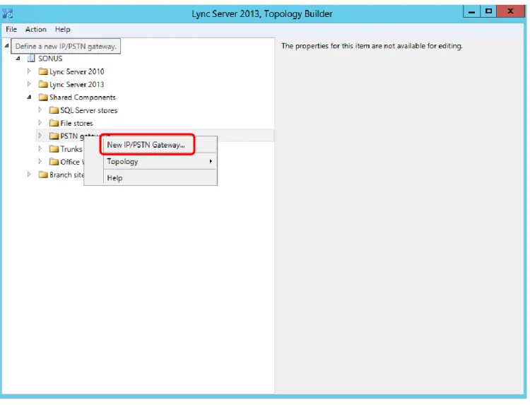
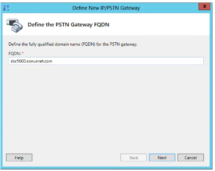
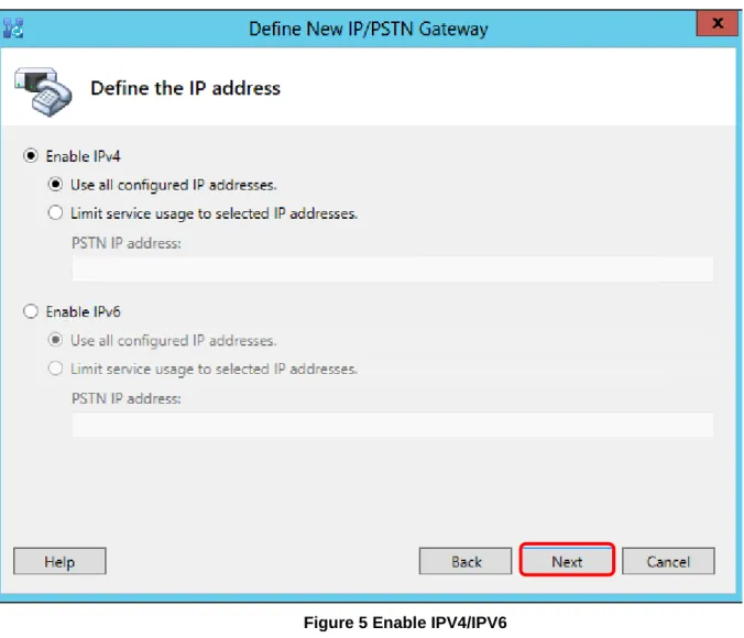
The Lync Server topology needs to be modified by adding the SBC as a Gateway device. The Gateway device
will be the interface to the Verizon SIP Trunk.
Open Lync Server Topology builder and load the current topology.
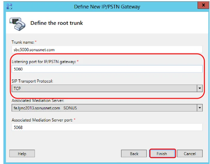
Expand the topology and Right Click on the ‘PSTN Gateways’ link in the left hand pane. Select “New IP/PSTN
Gateway…” from the menu as shown below and follow thru with the process.
Sonus – Network Design Group
33 of 54
Copyright © 2014, Sonus and/or its affiliates. All rights reserved.
Sonus – Network Design Group
34 of 54
Copyright © 2014, Sonus and/or its affiliates. All rights reserved.
Sonus – Network Design Group
35 of 54
Copyright © 2014, Sonus and/or its affiliates. All rights reserved.
Sonus – Network Design Group
36 of 54
Copyright © 2014, Sonus and/or its affiliates. All rights reserved.
Figure 6 Define Trunk Port and Protocol
This section covers adding the SBC to the Lync Server 2013
5.1.2
routing.
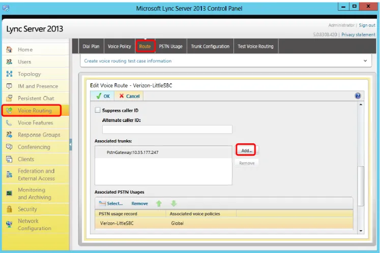
In order for Lync Server 2013 to send calls to the Verizon SIP Trunk the SBC will have to be added to the
Routing. Open Lync Server Control Panel and click on the Voice Routing link on the left hand pane. Click on
the Route tab on top of the right hand pane and scroll down to show the dialog below:
Sonus – Network Design Group
37 of 54
Copyright © 2014, Sonus and/or its affiliates. All rights reserved.
Sonus – Network Design Group
38 of 54
Copyright © 2014, Sonus and/or its affiliates. All rights reserved.
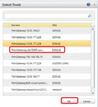
Figure 8 Select Trunk
Ensure the SBC is highlighted in the dialog shown above and click “OK’. At this point commit these changes to
the topology.
Sonus – Network Design Group
39 of 54
Copyright © 2014, Sonus and/or its affiliates. All rights reserved.
6 SBC and Lync 2013 Specific Configurations
Depending upon the type of call scenario desired will determine what settings are required for the SBC and
Microsoft Lync 2013 product.
6.1 Initial Setup for All Calls
DM/PM Rules
6.1.1
Digit Manipulation rules were required for the purpose of mapping preconfigured Lync 2013 user extensions
to established Verizon SIP Trunk DIDs. This is not expected to be a requirement for deployment scenarios.
For details of the DM/PM configuration please refer to Appendix A.
10-Digit Dialing
6.1.2
Normal calling pattern was to dial all 10 digits of a national number. 7 digit and extension dialing was not
included as part of the SIP Trunk interoperability testing. Other dialing patterns tested include Operator
Assistance calls, N11 codes, local/toll calls, and international calling.
6.2 Initiating Transfers with REFER
Call transfer via REFER method – Not Supported
6.2.1
Microsoft Lync Server 2013 is incompatible with Verizon network call transfer using the SIP REFER
Method. The contents of the REFER-TO Header in the SIP REFER message sent by Microsoft Lync are not
acceptable to the Verizon SIP Trunk.
6.3 Initiating Transfers with Re-INVITE
Call transfer via Re-Invite method
6.3.1
Transferring a call to another phone number is supported via the RFC3261 method. No special flag is
required to be set for this method. Ensure that on MS Lync 2013 under the “Trunk Configuration” element
that REFER support is set to “none”.
Sonus – Network Design Group
40 of 54
Copyright © 2014, Sonus and/or its affiliates. All rights reserved.
6.4 Call Hold
Call Hold via RFC3264
6.4.1
Placing a call on hold is via the RFC3264 method. This method is the preferred method for connections on
Verizon SIP Trunks. This method involves sending a Re-INVITE with the parameter “a=inactive”. No special
flag is required to be set for this method.
Sonus – Network Design Group
41 of 54
Copyright © 2014, Sonus and/or its affiliates. All rights reserved.
7 Appendix A – DM/PM Criteria and Rules
7.1 DM/PM Criteria
Lync 2013 to Verizon SIP Trunk number manipulation
7.1.1
Due to the nature of the test lab Lync 2013 Mediation Server in relation to other equipment in the test
environment, it was mandatory to create Digit Manipulation Criteria and Rules to map the Verizon
assigned SIP Trunk DIDs to pre-existing DIDs on Lync. What follows is a description of these settings. It is
not expected that DM/PM criteria and rules would be required in a typical customer deployment.
7.1.1.1
DM/PM Criteria – Lync 2013 numbers
DM/PM Criteria for Lync extensions. These are pre-configured numbers in the lab environment. From the
DM/PM Rules and call flow perspective these are considered the called numbers.
set profiles digitParameterHandling dmPmCriteria 2125881000 criteriaType digit digitType callingNumber parameterPresenceCheck exists
commit
set profiles digitParameterHandling dmPmCriteria 2125881000 digitCriteria digitMatch value startDigitPosition 0 numberOfDigits 10 matchValue 2125881000
set profiles digitParameterHandling dmPmCriteria 2125881000 digitCriteria digitMatch operation equals set profiles digitParameterHandling dmPmCriteria 2125881000 digitCriteria egressFlag value send operation ignore
set profiles digitParameterHandling dmPmCriteria 2125881000 digitCriteria natureOfAddress value 950 operation ignore
set profiles digitParameterHandling dmPmCriteria 2125881000 digitCriteria numberLength value 10 operation equals
set profiles digitParameterHandling dmPmCriteria 2125881000 digitCriteria numberingPlanIndicator value data operation ignore
set profiles digitParameterHandling dmPmCriteria 2125881000 digitCriteria presentationMatch value none operation ignore
set profiles digitParameterHandling dmPmCriteria 2125881000 digitCriteria screeningMatch value none operation ignore
commit
set profiles digitParameterHandling dmPmCriteria 2125881001 criteriaType digit digitType callingNumber parameterPresenceCheck exists
commit
set profiles digitParameterHandling dmPmCriteria 2125881001 digitCriteria digitMatch value startDigitPosition 0 numberOfDigits 10 matchValue 2125881001
set profiles digitParameterHandling dmPmCriteria 2125881001 digitCriteria digitMatch operation equals set profiles digitParameterHandling dmPmCriteria 2125881001 digitCriteria egressFlag value send operation ignore
set profiles digitParameterHandling dmPmCriteria 2125881001 digitCriteria natureOfAddress value 950 operation ignore
set profiles digitParameterHandling dmPmCriteria 2125881001 digitCriteria numberLength value 10 operation equals