Mug for Tremors
Team 183a1
Final Design Review
Sponsored By: QL+
by
Logan Smith - [email protected]
Allen Tecson - [email protected]
Jaret Wedow - [email protected]
Kai Workman - [email protected]
Mechanical Engineering Department
Statement of Disclaimer
Executive Summary
Table of Contents
1.0 Introduction ... 1
2.0 Background ... 1
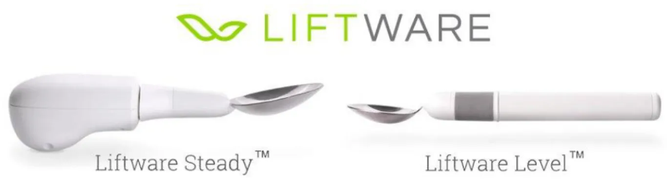
2.1 Liftware™ Self-Stabilizing Fork & Spoon ... 1
2.2 HandSteady Cup ... 2
2.3 Imagiroo ... 2
2.4 Technology ... 3
2.5 Patents ... 4
3.0 Objectives ... 4
3.1 Customer Needs and Wants ... 5
3.2 Quality Function Deployment ... 6
3.3 Engineering Specifications ... 6
4.0 Concept Design ... 7
5.0 Final Design ... 11
5.1 3D Printed Components ... 11
5.2 Final Assembly ... 15
5.3 Electronics ... 17
5.4 Software ... 17
5.5 Motors ... 18
5.6 Safety Analysis ... 20
5.7 Cost Analysis... 21
6.0 Product Implementation and Manufacturing ... 21
6.1 Initial Manufacturing Plan ... 22
6.2 Changes for Final Prototype ... 22
6.2.1 New Motors ... 22
6.2.2 New 3D Printed Parts ... 23
6.2.3 New Final Assembly ... 27
6.3 3D Printing Process ... 29
6.4 Bill of Materials ... 31
6.5 Operators Manual ... 32
7.0 Design Verification ... 36
8.0 Project Management ... 37
9.0 Conclusion ... 38
Works Cited ... 40
List of Figures
Figure 1: Liftware™ Self-Stabilizing Spoon (Hagen) ... 2
Figure 2: HandSteady Cup (“Home”) ... 2
Figure 3: Imagiroo Cup (“Picture of Imagiroo Cup on a Table.”)... 3
Figure 4: Internal System of Liftware (“Liftware™”) ... 3
Figure 5: Gyro Mug Boundary Sketch... 5
Figure 6: Functional Decomposition ... 8
Figure 7: Concept Sketches ... 9
Figure 8: Concept CAD – 3 and 2-Axis Rotating Gimbal Designs ... 10
Figure 9: Handle ... 12
Figure 10: Bracket... 12
Figure 11: Mug Shell ... 13
Figure 12: Mug Liner ... 14
Figure 13: Mounting Fixture ... 14
Figure 14: Exploded CAD Assembly ... 15
Figure 15: Mug Assembly ... 16
Figure 16: Structural Prototype ... 16
Figure 17: Wiring Diagram ... 17
Figure 18: Controller Board Software Interface ... 18
Figure 19: Controller Board Real Time Data ... 18
Figure 20: Diagram for 3D Dynamics Analysis ... 19
Figure 21: Tiger GB36-1 Brushless Gimbal Motors (“Tiger GB36-1 Brushless Gimbal Motor (Hollow Shaft).”) ... 23
Figure 22: Updated Bracket Design for Final Prototype ... 24
Figure 23: Updated Handle Design for Final Prototype ... 24
Figure 24: Updated Mug Liner Design for Final Prototype ... 25
Figure 25: Updated Mug Shell Design for Final Prototype ... 26
Figure 26: Updated Mounting Fixture Design for Final Prototype ... 26
Figure 27: Exploded CAD Assembly View of Final Design ... 27
Figure 28: Completed CAD Assembly for Final Design ... 28
Figure 30: Monoprice Maker Ultimate in Kai’s bedroom ... 29
Figure 31. 3D Printer in Process of Printing Mug Handle ... 30
Figure 32. 3D Printer in Process of Printing Mug Body... 30
Figure 33. 3D Printer in Process of Printing Mug Liner and Bottom of Mounting Fixture ... 31
Figure 34: Attaching Motor to Handle... 32
Figure 35: Attaching Bracket to Motor ... 33
Figure 36: Attaching Motor to Mug Shell ... 33
Figure 37: Attaching Bracket to Mug Shell ... 34
Figure 38: Assembling Mounting Fixture Components ... 34
Figure 39: Placing Mounting Fixture Assembly in Mug Shell ... 35
List of Tables
Table 1: Table of needs and wants for a mug designed for individuals with hand tremors. ... 5
Table 2: Table of engineering specifications with target values, tolerance, risk, and compliance. 7 Table 3: Morph Matrix... 8
Table 4: Weighted Decision Matrix ... 9
Table 5: Cost Analysis of Structural Prototype ... 21
Table 6: Bill of Materials ... 31
1.0Introduction
Quality of Life Plus was founded in 2008 by Jon Monett as a way to give back to wounded veterans in the community. Through QL+, unique engineering solutions are designed, developed, and produced to improve the quality of life of wounded veterans. Student teams at California Polytechnic State University, San Luis Obispo have completed over 100 engineering challenges since the creation of QL+.
Melissa Oliver, an occupational therapist at McGuire VA Medical Center, works extensively with veterans who struggle with certain daily activities due to their hand tremors. Hand tremors caused by essential tremor, Parkinson’s Disease, or other physical or neurological impairments can greatly affect an individual’s ability to perform daily tasks. One of these tasks include the ability to handle beverages, as hand tremors can cause excessive sloshing and spilling of liquid. Melissa reached out to find a way to help veterans with hand tremors easily consume liquids. Our team, consisting of Logan Smith, Allen Tecson, Jaret Wedow, and Kai Workman, was tasked with creating a stabilizing mug capable of resisting motion due to hand tremors. The following document details the design process our team took to research, design, prototype, and iterate our way to the final prototype that was created.
2.0Background
To understand the challenge proposed to us, understand our project requirements, and decide on a reasonable scope for the project, we conducted research on products and concepts in the market or in development that are like our project. We can use these products to benchmark our mug, as well as use technology already developed. Along with product research, we also investigated various patents of products that could help with stabilization and not spilling the liquid. These include electrically controlled stabilizing systems and geometries that reduce tremors or liquid spillage.
2.1Liftware™ Self-Stabilizing Fork & Spoon
Figure 1: Liftware™ Self-Stabilizing Spoon (Hagen)
2.2HandSteady Cup
The HandSteady cup, shown in Figure 2, features a rotating handle, designed for people with tremors, pain, or limited dexterity (“Home”). While the HandSteady cup does satisfy a few criteria set by our sponsor, the design has several issues with solving drinking problems associated with hand tremors. The handle only pivots along one axis of rotation, so it does not reduce the effects of hand tremors in the other axis. The cup also has to be refilled frequently due its small carrying capacity of only 9 fluid ounces.
Figure 2: HandSteady Cup (“Home”)
2.3Imagiroo
Figure 3: Imagiroo Cup (“Picture of Imagiroo Cup on a Table.”)
2.4Technology
Different technologies exist that counteract many of the involuntary motions that come with hand tremors. For our project, we initially planned to take inspiration from the Liftware™, which bases its technology around motion sensing and motor actuation. The internal system of the Liftware™ spoon, shown in Figure 4, features different electronic parts, such as sensors, microcontrollers, and motors. Through these devices, any tremor motions that occur will be detected and corrected, reducing the shaking effects and improving the practicality of the mug.
Later during the project, we began looking into different technologies that would accomplish the same goals the Liftware™ spoon was accomplishing. The main type of technology we found was a slightly different application of gimbal technology, this time based on the design of camera stabilizers. These camera stabilizers feature linkages that branch out from the cup and that control one axis of rotation at a time. The purpose of a gimbal-type handle is very similar to the Liftware™ spoon, in which it provides a rotation to the handle without rotating the base cup in order to effectively counteract tremor motions that occur on the handle. The difference is in how and where the rotation is applied. Primarily, the design of a camera stabilizer features a longer handle that allows for more components to be utilized while not increasing the volume of the cup to a size that is not aesthetically pleasing or feasible to carry.
2.5Patents
In order to find out if there are any products with the technology we need, we searched through patents that focused on passive and active solutions to preventing spillage or vibrations of any kind. The patents we examined are listed in Appendix A and showcase products and technologies that are already being used. The first patent focuses on an active gimbal that accounts for rotation in three axes. This would allow our mug to counteract tremors rotating about any axis. The patent also lists how to prevent different axes from becoming locked, which can often happen with gimbals if components rotate too far. The next three patents focus on geometrical or form factors to reduce tremors. The first one describes a specific type of handle that is larger and easier to grip so people with tremors have more control over a utensil. The second patent has physical obstructions on the inside of the cup that limit the amount of liquid that can come out. The third patent is similar to the second but has inner baffles to keep the fluid from spilling. The final patent in the list is one for decreasing vibrations for cameras on vehicles. It uses a two-gimbal system to counteract all vibrations while filming movie scenes shot from moving vehicles. All of these patents will prove useful in the ideation stage and can possible be adapted to prevent the spillage of liquid in a cup.
3.0Objectives
There are currently no cups or mugs on the commercial market that are effective for people with hand tremors. All cups aimed to help individuals with hand tremors are either not effective, carry too little of liquid, are too heavy, or are aesthetically unpleasing. People that have hand tremors need a mug that reduces the effects of these tremors and make it easy to drink from while still looking like a traditional mug. We aim to develop a mug that reduces the effect of hand tremors, can carry at least 16 ounces of liquid, is lightweight, and is aesthetically pleasing.
hand is included in the boundary diagram, we will need to make sure that the mug can be used by a variety of hand sizes.
Figure 5: Gyro Mug Boundary Sketch
3.1Customer Needs and Wants
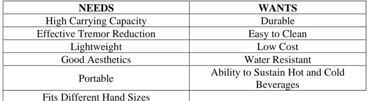
After speaking with our sponsor, Melissa Oliver, we constructed a list of the needs and wants that the veterans have regarding mugs that are designed for people with hand tremors. From this conversation, we identified the functions that will be necessary in our mug design. These functions are a high liquid carrying capacity, effective tremor reduction, lightweight, portable, fits different hand sizes, and looks good. Some of the less necessary functions are that the mug should be durable, easy to clean, and is affordable. The complete list of need and wants can be seen in Table 1.
Table 1: Table of needs and wants for a mug designed for individuals with hand tremors.
NEEDS WANTS
High Carrying Capacity Durable
Effective Tremor Reduction Easy to Clean
Lightweight Low Cost
Good Aesthetics Water Resistant
Portable Ability to Sustain Hot and Cold
3.2Quality Function Deployment
We applied the quality function deployment (QFD) process to ensure we have identified the correct problem and that we are meeting the necessary specifications. We created a house of quality diagram to highlight the specifications and requirements of the problem. The house of quality has sections for who, how, now, what, and how much, as well as the interaction between these elements. This diagram is included in Appendix B. The “who” section listed the parties that would benefit from this project: the veterans and other individuals who struggle to drink due to their hand tremors. The “what” section states customer requirements, in the form of needs and wants. Quantifiable, testable engineering specifications were stated in the “how” section. The interaction between these specifications and the customer needs is shown in the center of the house of quality. Making the QFD challenged us to determine which engineering specifications were needed in order to have a way to quantifiably determine if the customer’s needs and wants were met. This allowed us to then clearly identify the objectives that our mug is going to have to be able to accomplish and be able to rank the importance of these objectives. From the QFD it is obvious that our main objective is to make sure that our mug effectively reduces the effects of hand tremors, otherwise it would be like any other mug currently on the market. The second most important objective will be making sure the mug stays relatively small. If the mug is too big than it will not be portable, lightweight, aesthetically pleasing, and overall effective.
The QFD also allowed us to compare how we want our mug to perform based on how products currently on the market perform. The HandSteady Cup and the Imagiroo Cup both performed quite bad because they are pretty much just normal cups that only benefit one function. The Liftware™ performed the best out of the products currently on the market, but its major drawback is that it is a spoon and not a mug. Because of this we want our mug to perform just as well as the Liftware™ but be able to carry the same amount of liquid as a mug.
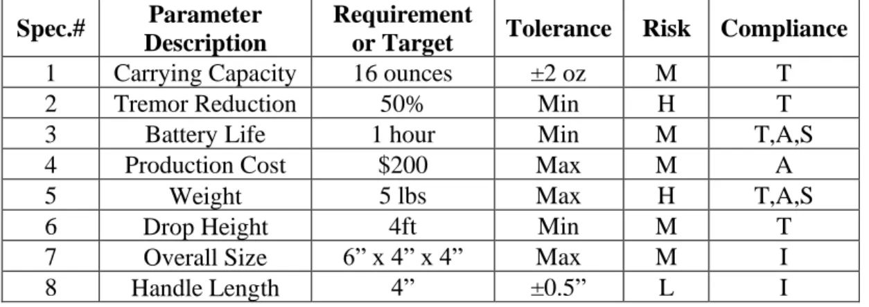
3.3Engineering Specifications
overall weight of the mug to a minimum. We chose 5 pounds including liquid to be our baseline weight as it gives some room to experiment with different electronics and batteries. We believe this weight will be a challenge to meet because of all the different components we might need to incorporate in our mug. Our sponsor mentioned that if the mug is too heavy, she is worried that it will amplify the tremors we are hoping to counteract. We must also make sure that our handle can be used by a variety of users. According to an article about average reviewed by Doctor Weatherspoon, NASA and the CDC report that the average hand breadth size for adult males and females in the U.S. is 3.5 and 3.1 inches respectively. This means we need our mug’s handle to be at least 3.5 inches long, so we chose 4 inches to accommodate for veterans who may have larger hands. We decided that for our mug to be considered durable, it should be able to withstand a drop of at least 4 feet. This height is that from the top of a standard table onto the ground. Table 2: Table of engineering specifications with target values, tolerance, risk, and compliance.
Compliance: Test, Analysis, Inspection, or Similarity
Spec.# Parameter Description
Requirement
or Target Tolerance Risk Compliance
1 Carrying Capacity 16 ounces ±2 oz M T
2 Tremor Reduction 50% Min H T
3 Battery Life 1 hour Min M T,A,S
4 Production Cost $200 Max M A
5 Weight 5 lbs Max H T,A,S
6 Drop Height 4ft Min M T
7 Overall Size 6” x 4” x 4” Max M I
8 Handle Length 4” ±0.5” L I
We will need to have different tests in order to measure how well our mug satisfies these engineering specifications. To test the carrying capacity we will pour as much liquid as we can into our mug and measure how much fits. To test the tremor reduction capabilities, we will use a high-speed camera to measure how much the cup moves compared to how much movement is put into the handle. To test battery life, we will use the mug continuously and see how long it lasts before the battery dies. To test the weight of the mug we will weigh the final prototype full of water.
4.0Concept Design
Figure 6: Functional Decomposition
Once basic functions were decided on, our group came up with concept models per basic function to ideate and physically represent potential solutions. The main functions we focused on were “hold water” and “apply rotation,” with “apply force” as a possibility, but our group recognized that applying a force is not as important (and may not even be needed) as applying a rotation. We then created a morph matrix, shown in Table 3, to highlight different combinations of design characteristics. By comparing cup type, rotation method, type of handle, and handle connection location, we realized that the rotation type was the most important aspect of our design. We determined that some of the other characteristics, such as type of handle, were dependent on the rotation type selected.
Table 3: Morph Matrix
Cup Type Rotation Type of Handle Handle Connection Location
Bottle Gimbal One Connection Top
Coffee Mug Bevel Gears No Handle Middle
Bowl Gravity Mug Two Connections Bottom
Ball & Socket
or other elastic suspenders to absorb the shock of the tremors. We decided that this would not be as effective as an actively powered device, so we eliminated this decision as well. The final concept generated was a gimbal device, like those used in camera stabilizers. We decided to move forward with this design, as it seemed feasible to design and implement along with being effective at reducing tremors. In order to help us make this decision to move forward with the gimbal design, we implemented a weighted decision matrix.
Figure 7: Concept Sketches
The weighted decision matrix, shown in Table 4, compares the various possible solutions using factors that are important to the design. By adding different weights to each of the factors, we could put more emphasis on the factors that were most important to the success of our final product. We determined that effectiveness in reducing tremors and feasibility of the design were the two most important factors in our decision-making process. Other factors we included were weight, aesthetics, manufacturability, and cost. We compared the four concept ideas we generated, along with our cup with lid baseline. The decision matrix resulted in the gimbal receiving the highest overall score, so we decided to continue with this design.
Table 4: Weighted Decision Matrix
Once we decided to move forward with the gimbal design, we created concept CAD models of our design shown in Figure 8. We initially were focused on a 3-axis design, which would utilize 3 motors to reduce tremors in all 3 possible directions of rotation. After more consideration, we decided to also consider a 2-axis design for our mug. This would prevent rotation of the mug in 2 axes, but not along the vertical axis. Our group is considering this 2-axis design because hand tremors that result in the cup rotating in the vertical axis does not occur as often as rotation along the other two axes and rotation along the vertical axis does not result in as much liquid spillage in comparison to the other two axes of rotation. Moving forward, we need to compare the two possible solutions and determine which one will more effectively solve the issue we are faced with. The 2-axis design will be easier to implement, in addition to being more stable design due to the
Factors Weights Gimbal Bevel Gears Gravity Mug Ball & Socket
Cup With Lid (Baseline)
Effectiveness 10 10 6 3 3 9
Weight 6 5 6 7 8 10
Aesthetics 4 7 5 5 7 3
Manufacturability 6 3 4 8 7 9
Feasibility 10 7 7 5 4 0
Cost 4 3 4 7 7 9
weight of the cup being below the motors rather than above. If we can determine that losing the vertical axis of rotation will not have a significant effect on our tremor reduction, we feel that the 2-axis design will be a better design to pursue. We will be conducting tests on a mug full of water to see if we can eliminate the need for control over the vertical axis.
Figure 8: Concept CAD – 3 and 2-Axis Rotating Gimbal Designs
Regardless of whether the gimbal will be controlling 2 or 3 axes of rotation, the main components required will still be the same. We will need electric motors that will apply the rotation to brackets that are connected to the mug. An accelerometer is needed to communicate to a controller when and how much the mug is being moved. Given this data, the controller will have to be coded to then tell the motors how much to move in order to keep the mug stationary. Finally, a battery is needed to power all the components. These electrical components will need to be selected to be able to all work together and satisfy the requirements of our mug.
the connection to the handle will be 2 kilopounds per square inch (ksi). This is well under 4.8 ksi, the ultimate strength of the plastic we plan to print the bracket out of. Given this information, the bracket will be robust enough to not break. As we begin to finalize dimensions of the mug and determine which electrical components will be used, we will be able to construct more accurate loading scenarios.
There are several challenges we face moving forward with this project. Our team has little experience with gimbals and the coding and control systems that will be required to make them function properly. Fortunately, Cal Poly Mechanical Engineering professor, Dr. Siyuan Xing, has agreed to serve as a technical advisor for our team moving forward. He has experience with control systems, so we will approach him with any difficult technical issues we are working through. We also have a limited timeframe to complete this project. Since we began the project at a later date, we may not have time to iterate through to a final design that is as lightweight, compact, and aesthetically pleasing as possible. Our focus is to create a functioning prototype that effectively assists in tremor reduction for users, even if we do not reach a final marketable product. During our PDR Presentation, a few other design concerns were brought up. The 2-axis design would currently only allow for right-handed drinking, so we are looking into ways to alter the design to make it usable with either hand. Additionally, we will need a way to lock one axis of rotation in order for the user to tip the mug and drink from it. While we have not yet settled on a final solution for this, possible solutions include a button to lock rotation or a band pass filter to allow slow movements to occur without activating the motors.
5.0Final Design
After taking into account the feedback we received during our PDR and CDR presentations, we were able to iterate and refine our design down to a final design, complete with a structural prototype. Our final design features a two-axis stabilizing system to actively reduce the motion of the cup due to hand tremors. It features five main 3D printed components, along with purchased electrical components. These five 3D printed components are composed of PLA.
5.13D Printed Components
Figure 9: Handle
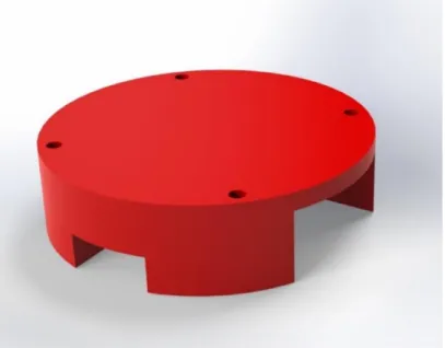
The bracket, which is shown in Figure 10, connects the handle to the body of the mug. A motor is mounted on both sides of the bracket, with one side on the mug handle and the other side on the outer mug shell. To ensure proper alignment during mounting and account for any misalignments in bracket or motor dimensions, we implemented mounting slots rather than holes.
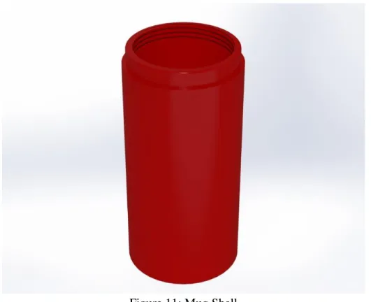
The outer mug shell, shown in Figure 11, contains the mug liner, along with the Inertial Measurement Unit (IMU), controller board, and battery. It is the large overall structure that gives the mug its shape. We included small cutouts to allow for wire routing and management. The top of the mug features threads to allow for an easy interface with the mug liner. We designed the mug shell to have a gap of approximately 2 inches between the bottom of the shell and the bottom of the liner when it is fully installed. This gap is where the battery, controller board, and IMU are stored. These components are held in place by the mounting fixture shown in Figure 13. The wires are routed from the motors down along the mug shell wall, where they connect to the controller board.
Figure 11: Mug Shell
Figure 12: Mug Liner
We designed a mounting fixture to hold the controller board, IMU, and battery secure in the bottom of the mug shell. These components need to be firmly held in place to ensure the mug does not experience any issues with connectivity or performance during usage. The mounting fixture, which is shown in Figure 13, also helps with easily removing the electronic components of the design if any issues arise that require troubleshooting. It attaches to the bottom of the mug shell with one mounting screw; removing this screw allows the mounting fixture assembly to be lifted and removed from the remainder of the mug assembly.
5.2Final Assembly
An exploded assembly view of our CAD model is shown in Figure 14. This highlights the various components of our final design and shows how the components fit together in relation to each other in the final product.
Figure 14: Exploded CAD Assembly
Figure 15: Mug Assembly
The image in Figure 16 was taken while the prototype was partially disassembled for testing, so not all of the wiring and electrical components are included. We constructed this structural protype to prove that our final design was feasible and that we were able to incorporate the various structural and electrical components into a single product. While our finalized structural prototype currently utilizes brushless DC motors that we purchased along with our controller board, testing and analysis showed us that these motors do not provide enough torque to effectively reduce tremors. Therefore, motors with higher torques were tested and implemented into the mug design as we continued in our iterations towards a final prototype to deliver at Senior Project Expo.
5.3Electronics
The electrical components of our design consist of a battery, two brushless motors, an inertial measurement unit (IMU), and a controller board. The motors, IMU, and controller board came from a GoPro camera stabilizer. These components were separated from their initial housing and linkages and integrated into our mug design.
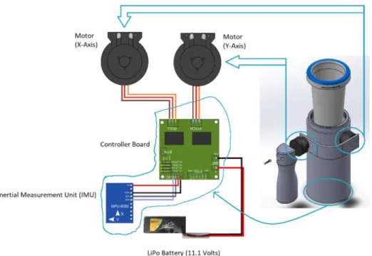
The various electrical components in our design are connected through wires, which are routed through our mug shell. The wiring diagram, shown in Figure 17, highlights the connection between these electrical components. The controller board serves as a central hub for all electrical components, relaying acceleration information from the IMU to the motors to initialize motion. The battery, IMU, and motors are all wired to connect with the controller board.
Figure 17: Wiring Diagram 5.4Software
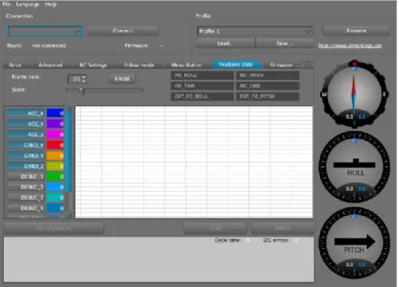
Figure 18: Controller Board Software Interface
The software also displays accelerations and gyro positions in real time on the grid space shown in Figure 19. This helped us in our calibration and tuning process. Viewing this data in real time, along with changing necessary values on the interface shown in Figure 18, allowed us to iterate control settings until we achieved desirable results from the controller.
Figure 19: Controller Board Real Time Data
5.5Motors
to hand tremors. We performed a three-dimensional dynamic analysis to solve for the required motor torque. Figure 20 shows the appropriate axis orientation and all length dimensions of each component in terms of variables (a, r, h, w, and b). During all the torque calculations, the axis in the XY plane is lined up with the centroid of the motors and bracket.
To determine the torques needed by the motors, we performed the following steps in our solution process. First, we applied a force representing the hand tremor force to the handle in the direction normal to both the x and y axes. We then calculated the corresponding angular acceleration in along the axis of the applied force. We used this angular acceleration to calculate the torque needed by the respective motor. All these calculations, in equation form, as well as the diagram and corresponding analysis are shown in Appendix D.
To complete these calculations, we simplified the physical components (mug, mug liner, motors, bracket, and handle) into basic geometry. We input exact values for length, masses, and moments of inertia into a MATLAB script for final calculations. As a result of this analysis, we determined that for a 5-pound tremor force applied to a handle, the two motors controlling the axes of rotation need to apply a torque of 2.94 N-m and 1.26 N-m respectively. We will use this knowledge to select motors rated for high enough torque as we iterate our design further.
5.6Safety Analysis
We performed a safety analysis on our design to identity potential hazards and failures and plan how to overcome these hazards in our design process. We created a design hazard checklist, which is included in Appendix E, to identify the potential hazards. Main hazards we identified include electrical components being exposed to water and moving linkages creating pinch points for the user. To counteract these hazards, we planned corrective actions for each case. To prevent electrical components from being exposed to water and shorting out, we will conduct performance tests without liquid in the mug. We will also ensure there is no exposed wiring, and that the mug liner is properly installed and watertight before introducing any liquid to the system. To prevent pinch points from harming the user, we ensured that our design minimized pinch points and placed them in areas less likely to affect the user.
5.7Cost Analysis
Table 5 shows all items used in our structural prototype and the cost of each of them. Our structural prototype came out to be much cheaper than we anticipated because we were able to 3D print all of our custom components. We were able to print for free through the QL+ lab so this drastically brought cost down. Additionally, we found a 2-axis gimbal assembly for a drone on eBay that contained all of the necessary electrical hardware needed to make our mug work for a very low price. Note that in Table 5, Part numbers 10007-10012 were all included in the gimbal assembly purchased on eBay, so the price listed for 10007 is the overall gimbal assembly cost.
Table 5: Cost Analysis of Structural Prototype
Part # Description Quantity Cost Total Cost
10001 Mug Shell 1 $0.00 $0.00
10002 Mug Liner 1 $0.00 $0.00
10003 Bracket 1 $0.00 $0.00
10004 Handle 1 $0.00 $0.00
10005 Mounting Fixture 1 $0.00 $0.00
10006 11.1V LiPo Battery 1 $16.14 $16.14
10007 Brushless 2-8 Series Motor 2 $35.72 $35.72
10008 BGC 3.1 Brushless Gimbal Controller 1 - -
10009 GY6050 Sensor (IMU) 1 - -
10010 Motor Cable 2 - -
10011 IMU Cable 1 - -
10012 Power Cable 1 - -
10013 M3x0.5-14mm Socket Head Cap Screw 8 $0.11 $0.85
10014 M2x0.4-10mm Socket Head Cap Screw 6 $0.10 $0.59
Total $53.30
6.0Product Implementation and Manufacturing
pandemic. Fortunately for our group, one team member had access to his own 3D printer. Since the manufacturing of our mug relies on 3D printed parts, we were able to continue iterating and producing prototypes.
6.1Initial Manufacturing Plan
Our initial plans for manufacturing our mug prototypes were outlined before we began making our structural prototype. We planned to acquire all the necessary parts for our mug from various sources. To manufacture our 3D printed parts, we used the QL+ lab on campus with a Ultimaker 3 printer.
Along with the printed components, we purchased some off the shelf parts to complete our design. The electronic components of the mug were extracted from an FPV 2-Axis Brushless Gimbal meant for GoPro cameras. These components include a controller board, an internal measurement unit (IMU), two motors, and wires to connect everything together. The entire gimbal was purchased online from eBay. The one electrical component not included in the gimbal system was the power supply. For this, we purchased a Tattu 11.1V LiPo battery from Amazon to power the entire system. Finally, to hold the mug together and to integrate the gimbal into our mug, we used M2.5 and M3 screws ordered online from McMaster Carr.
Once we completed building our structural prototype, we were able to test our mug for basic functionality and inspection purposes. After being able to test our design in use and receive feedback, we identified different components of the mug that could be improved on. As a result, a second iteration of our prototype was developed. The changes included in the final prototype are highlighted in the next section.
6.2Changes for Final Prototype
After the completion of our Critical Design Review (CDR), our first prototype design was iterated to incorporate feedback received during our review, along with implementing certain design changes we felt were necessary for the success of the project. The general design was kept the same, but the new prototype saw changes in the individual parts of the mug. Major design changes included incorporating stronger motors, stabilizing the IMU, and replacing the threaded liner with a key-lock mechanism to simplify manufacturing and product use.
6.2.1New Motors
that these motors did not provide enough torque to support and move the weight of the mug assembly. When the mug was subjected to slight tremors, the motors applied a little bit of power, but were unable to move the mug.
To overcome this problem, we upgraded to larger motors with higher torque outputs. Since we were buying these new motors as a standalone product rather than part of a gimbal system, we were able to look more closely into the specifications of the motors online. The motors we selected for our final design are Tiger GB36-1 Brushless Gimbal Motors, shown in Figure 21. These motors are much more powerful that the initial motors we used, rated at a payload of up to 4.2 pounds each. Due to the different dimensions of these motors, the fitting and sizing holes in our mug body, bracket, and handle were also changed.
Figure 21: Tiger GB36-1 Brushless Gimbal Motors (“Tiger GB36-1 Brushless Gimbal Motor (Hollow Shaft).”)
6.2.2New 3D Printed Parts
Figure 22: Updated Bracket Design for Final Prototype
As a result of feedback to make the handle more ergonomic and user friendly, the handle experienced another redesign after the completion of CDR. One of the recommendations for our handle was to utilize a horizontal overhang to allow the mug to rest on the hand. This idea was implemented in our new handle, shown in Figure 23, as an enclosed area to grip, similar to a coffee mug. This allows users with limited grip strength to easily pick up and hold the mug. The connection to the motor was changed to allow the edges to sit flush with the motors. The mounting holes were repositioned to align with the new motors, and the resulting bracket was more streamlined and ergonomically pleasing than the original.
We decided to improve the detachable liner, specifically the method in which the liner would attach and detach from the mug. The utilization of threads in our structural prototype caused a few problems. First, due to how the liner and base mug were 3D printed, there was an excessive amount of support material printed around the threads. This resulted in the required removal of the support material; a process that was time consuming, labor intensive, and even unsafe depending on the method of removal. Also, the practical use of threads brought up problems. Depending on the quality of print and the quality of removing the support material, the interface of the threads could end up being inadequate for commercial use. Rough edges would cause the threads to be get caught on themselves and due to the material being made of PLA, the thin threads would be susceptible to chip damage or full fracture. As a result of these issues, a new key-lock was designed and implemented. The CAD model of the new liner design are shown in Figure 24. This mechanism is much simpler to use and will be easier to 3D print with high quality. Our final prototype proved these improvements when in use, as the liner is now easier to attach and detach.
Figure 24: Updated Mug Liner Design for Final Prototype
Figure 25: Updated Mug Shell Design for Final Prototype
The mounting fixture, shown in Figure 26, also experienced some major changes. While troubleshooting performance issues with the structural prototype, we discovered a possible solution to the unstable vibrations was to ensure proper alignment and secure fastening of the IMU. To secure the IMU, a secondary structure was designed to attach to the top of the fixture. The remainder of the mounting fixture also featured some geometry updates to ensure it fit within our new mug shell design.
6.2.3New Final Assembly
An exploded assembly view of our final CAD model is shown in Figure 27, with all major parts and components labeled. It shows how the various components fit together in relation to each other to create our final product.
Figure 27: Exploded CAD Assembly View of Final Design
Figure 28: Completed CAD Assembly for Final Design
Once the final components were all redesigned and 3D printed, they were assembled into the final prototype shown in Figure 29.
6.33D Printing Process
To produce the custom components needed for our mug design, we utilized a 3D printer. The material we used and designed our model around was 1.75mm PLA as it is easily accessible to many 3D printers. As mentioned previously, two different printers were used in the making of our prototypes. The first is an Ultimaker 3 printer provided by the QL+ Lab. The second printer is the Monoprice Maker Ultimate provided by one of our group mates. Due to the size of our mug components, any printer with at least a 215x215x200mm build volume will work for printing. A picture of the Monoprice Maker Ultimate is provided in Figure 30.
Figure 30: Monoprice Maker Ultimate in Kai’s bedroom
Figure 31. 3D Printer in Process of Printing Mug Handle
Figure 33. 3D Printer in Process of Printing Mug Liner and Bottom of Mounting Fixture
6.4Bill of Materials
A final bill of materials is displayed in Table 6. This includes the cost for all components, both purchased and manufactured, that were used in our final prototype. The total cost for manufacturing our final prototype was $123.28.
Table 6: Bill of Materials
Part # Description Quantity Cost Total Cost
10001 Mug Shell 1 $3.66 $3.66
10002 Mug Liner 1 $2.89 $2.89
10003 Bracket 1 $0.54 $0.54
10004 Handle 1 $1.34 $1.34
10005 Mounting Fixture 1 $1.15 $1.15
10006 11.1V LiPo Battery 1 $16.14 $16.14
10007 Brushless 2-8 Series Motor 2 $29.88 $59.76
10008 BGC 3.1 Brushless Gimbal Controller 1 $35.72 $35.72
10009 GY6050 Sensor (IMU) 1 - -
10010 Motor Cable 2 - -
10011 IMU Cable 1 - -
10012 Power Cable 1 - -
10013 M2.5x0.45-6mm Socket Head Cap
Screw 8 $0.05 $0.37
10014 M3x0.5-6mm Socket Head Cap
Screw 8 $0.21 $1.71
6.5Operators Manual
We created a detailed operators manual to help with using the mug. It includes instructions for important tasks such as calibrating, using, and cleaning the device. The operator’s manual is in Appendix G.
6.6Assembly Instructions
Due to the flexibility of 3D printing the models we designed, the assembly of the mug only required screws. Detailed drawings for all custom manufactured components and exploded views to aid assembly are in Appendix H. The procedure to put the entire mug together is as follows:
To assemble:
1. Attach 1 of the Tiger Brushless Gimbal Motors to the handle using 4 M2.5x0.45-6mm screws.
2. Attach the other side of the motor to the bracket using 4 M3x0.5-6mm screws.
Figure 35: Attaching Bracket to Motor
3. Attach the second motor to the mug body using 4 M2.5x0.45-6mm screws
4. Attach the other side of the motor to the bracket using 4 M3x0.5-6mm screws
Figure 37: Attaching Bracket to Mug Shell 5. Assemble the mounting fixture assembly:
a. Secure the battery in the bottom slot of the mounting fixture using tape or other adhesive underneath the battery.
b. Secure the controller board in the mounting fixture by attaching the two mounting fixture halves together, with the mounting tabs passing through the controller board mounting holes.
c. Secure the IMU to the top of the mounting fixture using tape or other adhesive
6. Lower the mounting fixture into the mug body. Secure to the bottom of the mug shell by using 1 M3x0.5-6mm screw passing through the bottom of the mug shell and self-tapping into the mounting fixture. Hot glue can be used to secure the fixture into the bottom of the mug as well.
Figure 39: Placing Mounting Fixture Assembly in Mug Shell
7. Use the rectangular cutouts in the mug body to route the wires from the motors to the interior of the body, then attach the motor wires to the corresponding connection pins on the controller board.
8. Insert the mug liner into the mug body, lining up the key-lock tab on the liner with the key-lock cutout on the mug body. Rotate the liner clockwise to secure it in place.
Purchased components used in our final prototype:
• 9x M3x0.5-6mm and 8x M2.5x0.45-6mm screws from McMaster Carr
• BGC 3.1 Brushless Drone Gimbal kit from eBay, which was disassembled for its controller board and Inertial Measurement Unit (IMU)
• 11.1 Volt LiPo Battery from Amazon
• 2x Tiger GB36-1 Brushless Gimbal Motors from GetFPV 7.0Design Verification
As outlined in the Objectives section, we created eight engineering specifications that our design was required to meet. The first one is the overall liquid carrying capacity of 16 ounces. We also wanted to be able to reduce the effect of tremors by 50%. Next, our battery life was set to last for a minimum of one hour and our total production cost at a maximum of $200. The mug was required to weigh less than five pounds with liquid since weight can impact tremors negatively. The mug was also designed to survive a four-foot drop test and fit within a 6”x4”x4” envelope. Finally, the handle length was required to be 4” to allow for all hand sizes.
Due to COVID-19, our initial design verification plan had to be modified as our project came close to completion. Initially, we had plans to test or verify seven of our engineering specifications. However, due to time and resource restrictions placed on our team due to the uncertainties surrounding the spread of COVID-19, not all of our tests were able to be completed.
The first test completed was mug carrying capacity. We filled the mug liner with water and poured it into a Pyrex liquid measuring cup to ensure we met our requirement of a 16-ounce carrying capacity. Simultaneously, we were confirming that our design did not leak, and successfully contained the water. Both of these checks were successful, so the mug met our first design requirement.
The next test performed was for battery life. By leaving the mug powered on and providing input tremors through hand movements, we were able to verify that our mug could last through a whole meal without becoming dysfunctional. During our test, the mug battery lasted through one hour of continuous use, so it met this design requirement.
The weight of the system was determined by performing a simple inspection using a digital scale. We filled the mug with 16 ounces of water and verified that the mug, water, and all other components weighed less than five pounds collectively. This test was successful, as the mug assembly came out to a total weight of 1.9 pounds.
handle to ensure the grip area is large enough to accommodate most hand sizes. We used calipers to measure the height of the grip to compare to our 4-inch specification. Since the measured height was within 0.25 inches of our target 4 inches, we considered this specification met.
The two remaining design specifications were unable to be tested and verified due to the changing circumstances we faced as the project neared completion. Both tremor reduction tests and a structural drop test relied on access to materials or resources that we were unable to obtain. To test the tremor reduction of our system, we planned on using a high-speed camera to record an input into the handle and measure the angle that the mug itself moves. We were planning on using Cal Poly faculty member Dr. John Chen’s high-speed camera to run this test. However, due to campus being shut down, we were unable to gain access to this high-speed camera or any other one.
We planned on performing a drop test to ensure structural rigidity. By dropping the mug on a smooth concrete floor from a height of four feet and then powering the device on, we would be able to ensure it still works properly after experiencing a shock impact, which is a possible situation to occur during actual use. However, due to time restraints and the challenges of working remotely, we were unable to perform the drop test. We had limited access to supplies, so our team did not want to break a controller board or other component, which would prevent us from having a working prototype at the time of the senior project expo.
Our Design Verification Plan and Report can be seen in Appendix I. This document outlines each specification, the acceptance criteria, and the dates that each test was performed.
8.0Project Management
While designing the mug for tremors our biggest task was making it compact, attractive, and effective. The technology used to stabilize objects is already well engineered. Accelerometers are found in devices from drones to cell phones; however, getting all the electrical and mechanical components in a lightweight device that contains liquid is the main challenge. After understanding all of the electrical workings of accelerometers, motors, and computer chips used, we began to design a mug that can effectively conceal these components and reduce the effect of the tremors. Rapid prototyping was key in iterating our design and finding clever space saving solutions. Once we find a suitable design that holds the electronics and is aesthetically pleasing, we continued to fine tune the controller in order to reduce tremors as effectively as possible. As we iterated the design to reduce more tremors and cut down on weight, we narrowed down to the final device that is being presented to our challenger.
Table 7: Project Timeline
Deliverable Description Date
Preliminary Design Review Initial design direction for
approval 1/27/2020
Critical Design Review
Detailed design of updated solution with part drawings and costs
3/6/2020
Manufacture and Testing Review
Manufacturing plan, test manuals, and updated status of project
3/12/2020
Operational Manual Document safety hazards and
how to operate effectively 5/8/2020 Final Design Review Final design, prototype, and
report for presentation 6/5/2020
Due to the unfortunate events caused by COVID-19, we were unable to implement all of our design ideas. If we had been able to meet in person and have access to Cal Poly’s resources, we would have included a power button, an even better-looking design, and understand the software better in order to make our mug effective. We would have also liked to include a button or lever to be pushed while drinking to allow the mug to tip in one axis. If this project is extended to future teams, these are the new implementations that should be added and improved upon.
9.0Conclusion
When we started this project, we were tasked with delivering an effective, lightweight, and aesthetically pleasing product to solve the current issues veterans with hand tremors face when drinking liquids. This document outlines our background research, specification development, and concept design process, along with the iterations we took to reach a final design. Due to changing circumstances regarding COVID-19, we were unable to deliver a fully calibrated product that is as effective as we hoped to our sponsor. However, we finalized a compact, aesthetically pleasing design with all the hardware and electronic components needed to make this mug an effective solution to reducing hand tremors.
After completing this project, there are several design changes and improvements our team would make if given more time, or if COVID-19 did not drastically change the final few months of our design time.
down. Thus, we were not able to get technical advice from someone with more knowledge on the subject. We feel that properly calibrating and setting up the software for the mug would be a relatively simple and quick task for someone with experience, so we hope in the future that this design can be easily replicated and improved upon.
Additionally, if given more time to iterate until reaching a final design, our team would have optimized the motors to be more compact. More time for testing and feedback would have allowed us to find motors that were smaller than the ones currently selected, but still able to handle the loads imposed on the mug during use. If more compact motors were selected in the future, mounting holes on the bracket, handle, and mug shell would need to be updated to interface with the new motors.
Currently, the design does not feature a button or lever to disengage the motors. Adding this feature and disengaging the motors in one axis of rotation would make it much easier for users to tilt and drink from the mug. The software we currently use for tuning and calibrating the system has a parameter to add input signals from buttons and switches, so we feel it would be very straightforward to incorporate a small button on the handle that locks the rotation of the mug along one axis when pressed.
Works Cited
Hagen, Marc. “Picture of the Liftware™ Steady and Liftware™ Level.” Closing The Gap, Closing The Gap, Inc., 26 Oct. 2017, www.closingthegap.com/liftware-steady-level/.
“Home” HandSteady, handsteady.com/en-us/. “Imagiroo” Imagiroo, www.imagiroo.com/.
“Internal Diagram of How Liftware Steady Works.” Liftware Steady Starter Kit, Liftware, 2015, store.liftware.com/products/liftware-starter-kit.
“Liftware Steady.” Liftware, Verily Life Sciences, 2015, www.liftware.com/steady/.
Peacock, Chris. “Picture of HandSteady® Uses.” HandSteady®, HandSteady Ltd., 2017, handsteady.com/en/.
“Picture of Imagiroo Cup on a Table.” Imagiroo, 2014, www.imagiroo.com/.
Frothingham, Scott. “Average Hand Size: For Adults, Children, Athletes, and More.” Healthline, Healthline Media, 7 Aug. 2019, www.healthline.com/health/average-hand-size#adults. “Tiger GB36-1 Brushless Gimbal Motor (Hollow Shaft).” English,
Appendices
A. Table of Patents
B. Quality Function Deployment (QFD) C. Bracket Stress Calculations
D. Motor Torque Calculations E. Design Hazard Checklist F. FMEA
G. Operators Manual H. Drawing Package
Appendix A:Table of Patents
Patent Number Patent Title Description
US4052654A
Gyro stabilized inertial reference system with gimbal lock prevention means
This patent is about how a gyro allows freedom of rotation around the three axes and how to lock certain axes of rotations.
US20110005085A1 Eating Devices Which Reduce Tremors of the Hand
This patent changes the grip of how you hold silverware to help reduce tremors. It has a larger handle so someone could have more control of the silverware and not need to bend their wrist at strange angles
WO2007077009A2 Device for preventing undesired spilling of liquids from a container
A patent for a device that won’t spill using physical barriers instead of electronics. A
mechanical/geometric solution to no spillage.
US4130215A No spill beverage cup
This cup uses inner baffles that prevent liquid from splashing out. These baffles have holes to allow liquid to flow through for
drinking but not allow water to spill out of the cup when jostled.
US8179078B2 Handheld or vehicle-mounted platform stabilization system
Alpha_X = 32.174*12*Ft * ( ((h5/2)+r4) /
((Ixx1+Ixx2+Ixx3+Ixx4+Ixx5+Iyx3+Izx3) + ( (m1*(h1/2-a)^2) + (m3*y3bar^2) + (m4*(r3+w3+(h4/2))^2) + (m5*(r3+w3+(h4/2))^2) + (m5*(h5/2+r2)^2) )) );
% [rad/s^2]
Torque_X = Alpha_X * ( (m1*r1^2/4) + (m1*h1^2/12) + (m1*((h1/2)-a)^2) + m1*(h1^2-4));
% [lbm-in^2/sec^2]
% Torque in lbf-in
Torque_X_lbf_in=Torque_X/(32.174*12)
Torque_X_lbf_in =
26.0574
Published with MATLAB® R2019a
Appendix F:FMEA
Product: _Stabilizing Mug_
Team: __Mug For Tremors__
Design Failure Mode and Effects Analysis
Prepared by: __Jaret Wedow__
Date: _____6/4/2020___
System /
Function Potential Failure Mode Potential Effects of the Failure Mode
S e v er it y
Potential Causes of the Failure Mode
Current Preventative Activities O c cu re n c e Current Detection Activities Dete
c ti o n R P N Recommended Action(s) Responsibility & Target Completion Date Actions Taken S e v er it y O c cu re n c e C ri ti c al it y R P N Water Containment System / Water tight
Cup leaks - Electronics short, user is dissatisfied/wet 5
- 3D printed container not secured, Gap between liner and cup frame
- Check CAD model,
test material 3
- Normal use test (put water in the
cup)
4 60
- Check 3D printing process (primarily the final product before
implementing it with electronics)
Kai - Mid May
Mug liner tested before intergrating with electronics
5 2 2 20
Water Containment System / Water tight
Cup breaks - User is injured, water is not contained, product does not function 4
- 3D printed container not secured, 3D material weak/not waterproof, Impact from drop fractrues container, Gap between liner and cup frame
- Check CAD model (stress analysis/FEA), test material
3 - Normal use test
(max load test) 2 24 - - - 4 3 2 24
Electronics / Power the motor
Electronics short circuits - User is shocked, prodcut does not function 5
- Poor wire management (wire exposed/wire faulty/etc.)
- Insulate wires 2 - Checking circuit
after construction 3 30 - - - 5 2 3 30
Electronics / Power the motor
Runs out of power - Product does not function 2
- Runs out of battery power, Battery power drains faster than expected
- Include option to
replace battery 7
- Test battery life
of our battery 1 14 - - - 2 7 1 14
Electronics / Transfer tremor signal into motors
Loses communication - Product does not function 2
- Poor wire management (wires broken/wires pinched)
- Check wiring installation, check coding
4 - Normal use test 2 16 - - - 2 4 2 16
Electronics / Transfer tremor signal into motors
Code does not work properly - Product does not function, code could amplify tremors 3
- Code written wrong, test case failed/not accounted for
- Check coding (debug
a lot) 5
- Debug a lot/Normal use
test
5 75 - Confer with CS/CPE/ME
faculty/students Allen - March/ April
Professor Xing assisted with our coding and debugging
3 3 5 45
Electronics /
Actuate Motor Motor stops functioning - Product does not function 2
- Motor overheated/burnt out, faulty wiring, battery power out
- Select suitable
motors/batteries 3 - Motor use test 2 12 - - - 2 3 2 12
No power/not strong enough - Product does not satisfy user/meet needs 2
- Motor overheated/burnt out, faulty wiring, battery power out
- Select suitable
motors/batteries 4 - Motor use test 3 24 - - - 2 4 3 24
Linkage / Transmit motion to cup
Linkage break - Product does not function, water is not contained, user may be
injured 4
- Poor design (not enough analysis), material fracture (drop impact/poor 3D printing)
- Stress analysis 2 - Normal use test
(max load test) 2 16 - - - 4 2 2 16
Linkage deforms - Product may fail, product may not be as effective, not
aesthetically pleasing 3
- Poor design (not enough analysis), material fracture (drop impact/poor 3D printing)
- Stress analysis 2 - Normal use test
(max load test) 3 18 - - - 3 2 3 18
Linkage / Handle to user interface
Handle not comfortable - User is displeased 2 - Poor design, poor
choice of material
- Ergonomic research/analysis, material research/analysis
4 - User test (have
people hold it) 2 16 - - - 2 4 2 16
Handle flimsy/bending - Water spills out of mug, handle may break from mug 3
- Poor design (strength analysis), poor choice of material
- Stress analysis, material research/analysis
2 - Normal use test
(max load test) 2 12 - - - 3 2 2 12
Housing / Contain electronics saftey
Not watertight - Electronics short, user is wet/shocked 5
- 3D printed container not secured, 3D material weak/not waterproof, Impact from drop fractrues container, Gap between liner and cup frame
- Check CAD model,
test material 3
- Normal use test (fill up mug with
water)
4 60
- Check 3D printing process (primarily the final product before
implementing it with electronics)
Kai - Mid May
Mug Components tested before integrated with electronics
5 2 3 30
Faulty wiring - Electronics short, user is wet/shocked 5 - Poor instillation/design
of wiring, wear and tear - Wire
management/insulation 2
- Checking circuit
after construction 3 30 - - - 5 2 3 30
Appendix G:Operators Manual
Mug for Tremors User Guide
Operation
To turn on the device, connect the battery to the controller board using the small plug-in connecter. The liner must be removed to gain access to the battery cables. If the device has not been calibrated, follow the calibration guidelines. Once powered on and calibrated, the mug will actively reduce hand tremors at all times until powered off.
NOTE: The current version of the device does not have a power button, so the only way to activate and deactivate the power to the motors is to unplug the battery.
Caution: Do not expose electrical components to water.
This can cause the user to experience an electric shock and can damage the product. Make sure that the liner is properly secured before adding water.
Warning: This mug features moving components which can lead to pinch points
Calibration
Power on the device, then press and hold the small black button on the microcontroller for 3 seconds. Note that the Liner must be removed to have access to the controller board. Upon release, the controller indicator light will flash, and the motors will disengage. Position the assembly in the desired orientation, with the mug upright and handle oriented vertically. After 5 seconds, the controller board indicator light will stop flashing and the motors will start functioning again. The mug is now calibrated to the orientation
introduced by the user, and will resist tremors to maintain the calibrated orientation.
Maintenance
No active maintenance is required to keep the mug assembly working properly. Although the device is designed for repeated use, if 3D printed components wear out over time, they can be replaced by repeating the necessary manufacturing and assembly steps. The mug should not be exposed to extreme temperatures, as this can damage the electrical components.
Cleaning
The Mug features a removable liner, designed to quickly and easily be detached for
cleaning. Twist the liner to disengage the Key Insert that holds it in place, then lift the liner to separate it from the rest of the assembly. To sanitize the handle, bracket, or mug body, wipe down with a disinfectant wipe.
Charging
Appendix H:Drawing Package
Quanity Cost Total Cost Source More Info
10000
10001 1 $3.66 $3.66 Custom 3D PRINTED
10002 1 $2.89 $2.89 Custom 3D PRINTED
10003 1 $0.54 $0.54 Custom 3D PRINTED
10004 1 $1.34 $1.34 Custom 3D PRINTED
10005 1 $1.15 $1.15 Custom 3D PRINTED
10006 1 $16.14 $16.14 AMAZON
10007 2 $29.88 $59.76 EBAY
10008 1 $35.72 $35.72 EBAY
10009 1 - - EBAY
10010 2 - - EBAY LENGTHENED
10011 1 - - EBAY LENGTHENED
10012 1 - - EBAY LENGTHENED
10013 8 $0.05 $0.37 McMaster Pack of 25, Item 92290A056
10014 8 $0.21 $1.71 McMaster Pack of 50, Item 92290A111
Total $123.28 * All of the ebay parts sold as a kit
* IMU = Inertial Measurement Unit
* 3D printed parts cost calculated based on weight Power Cable
Handle
11.1V LiPo Battery
BGC 3.1 Brushless Gimbal Controller GY6050 Sensor (IMU)
Motor Cable IMU Cable
M2.5x0.45-6mm Socket Head Cap Screw M3x0.5-6mm Socket Head Cap Screw Bracket
GB36-1 Motor Mounting Fixture Mug For Tremors Assy
Part # Description
Part No: 10006 11.1V LiPo Battery
Brand: Tattu
Capacity(mAh): 450mAh
Voltage(V): 11.1V
Discharge Rate (C): 45C
Max Burst discharge Rate (C): 90C
Configuration: 3S1P
Net Weight(dev.20g): 40.5g
Length(dev.5mm): 55mm
Width(dev.2mm): 30.5mm
Height(dev.2mm): 16mm
Connector Type: JST-SYP-2P Plug
Wire Length(mm): 100mm
Balancer Connector Type: JST-XHR
Amazon Product Name:
Tattu 11.1V 450mAh 3S LiPo Battery Pack 45C with JST Plug for Small Size FPV E-flite Blade 180 CFX Torrent 110 Baby Hawk Micro 2
ASIN: B0714GN73V
Part No: 10007 GB36-1 Motor
Brand: Tiger Motors
Motor Dimensions (mm): 41.8x24.3
Shaft Size (mm): 5.6 hollow
Stator Bore: 25x25mm 4-M3
Rotor Bore: 15x15mm 4-M2.5
Kv Constant: 50
Motor Weight: 88g
Cable Length: 35cm
Configuration: 12N14P
Motor Torque: 1.5kg/4S
Internal Resistance: 15.6 Ω
Rated Voltage 3-6S
Part No: 10008, 10009,10010, 10011, 10012 2 Axis Brushless Gimbal, Controller & Sensor
Item Name: Brushless camera gimbal
Color: Black
Flight controller: BGC 2.2b2
Battery plug: JST
Weight: 212g / 7.5oz
Number of stabilization axes: 2
Power supply voltage: 8.18V (3s-4s LiPo) Maximum DC current to each motor: 2.8A
Limiting short-time current (with the
inclusion of protection) to each motor: 7.1A
Output current regulation: 8 or 32 KHz PWM
Sensor connection: I2C
Supported sensors: MPU6050
PC communication for configuration and
upgrade: on-board USB
Overcurrent protection: Yes
Overheat protection: Yes
Undervoltage protection: Yes
Reverse polarity protection: Yes
Dimensions: 50mm x 50mm
Mounting holes: M3, 45mm
Part No: 10013
M2.5x0.45-6mm Socket Head Cap Screw
6/4/2020 McMaster-Carr
https://www.mcmaster.com/92290A056 1/2
Super-Corrosion-Resistant 316 Stainless Steel Socket Head Screw
M2.5 x 0.45 mm Thread, 6 mm Long
$2.33 per pack of 25 92290A056
Head Typ e Soc k et
So c ket Head Pro file St and ard
Drive St yle Hex
Syst em o f Measurem ent Met ric
Thread Direc t ion Rig ht Hand
Thread Size M2.5
Thread Pit c h 0.45 m m
Thread Typ e Met ric
Thread Fit Class 6g
Leng t h 6m m
Thread ing Fully Thread ed
Thread Sp ac ing Co arse
Head
Diam et er 4.5m m
Heig ht 2.5m m
Drive Size 2 m m
Mat erial 316 St ainless St eel
Tensile St reng t h 70,000 p si
Hard ness Not Rat ed
Sp ec ific at io ns Met DIN 912, ISO 4762
RoHS Ro HS 3 (2015/863/EU) Co m p liant
REACH REACH (EC 1907/2006) (01/16/2020, 205 SVHC) Co m p liant
Co unt ry of Orig in Peo p les Rep ub lic Of China, o r Taiw an
These sc rew s are c orrosio n resist ant in w et environm ent s, no nm ag net ic , and elec t ric ally c o nd uc t ive. Leng t h is m easured fro m und er t he head .
Co arse t hread s are t he ind ust ry st and ard ; c ho ose t hese sc rew s if yo u d o n’t know t he p it c h o r t hread s p er inc h.
NUMBERPART
Information in this drawing is provided for reference only.
http://www.mcmaster.com
4.5 mm
2 mm Hex
2.5 mm
2.5 mm 6 mm
M2.5 x 0.45 mm Thread
92290A056
Stainless Steel Socket Head Cap Screw