J2X1-7677-05ENZ0(02)
June 2014
Windows/Linux
FUJITSU Software
ServerView Resource Orchestrator
Cloud Edition V3.1.2
Preface
Purpose of This Document
This manual explains the overview, setup, and operation of NS Option (*1), an optional product of FUJITSU Software ServerView Resource Orchestrator Cloud Edition (ROR CE).
*1: NS is the abbreviation of Network Service.
This manual focuses on explaining how to set up NS Option and make it available for use on systems where FUJITSU Software ServerView Resource Orchestrator Cloud Edition will be installed. Therefore, for content that is explained in FUJITSU Software ServerView Resource Orchestrator Cloud Edition manuals, only items are listed in this manual.
Intended Readers
This manual is written for system administrators who will use Resource Orchestrator to operate the infrastructure in private cloud or data center environments.
When using NS Option, it is assumed that readers have basic knowledge about FUJITSU Software ServerView Resource Orchestrator Cloud Edition.
Structure of This Document
This manual is composed as follows:Chapter 1 Overview
Provides an overview of NS Option.
Chapter 2 Design and Preparations
Explains how to design and prepare for NS Option installation.
Chapter 3 Setup
Explains the setup necessary for using NS Option.
Chapter 4 Operation
Explains how to operate NS Option.
Chapter 5 Maintenance
Explains the maintenance of the NS option.
Appendix A Commands
Provides an overview of the commands available in NS Option.
Appendix B Port List
Explains the ports used by NS Option.
Appendix C Pre-configuration Method for NS Appliances
Explains the preparations for performing auto-configuration using simple configuration mode for NS Appliance.
Document Conventions
The notation in this manual conforms to the following conventions.
-
When using Resource Orchestrator and the functions necessary differ due to the necessary basic software (OS), it is indicated as follows:[Windows Manager] Sections related to Windows manager [Linux Manager] Sections related to Linux manager [Windows] Sections related to Windows [Linux] Sections related to Linux [Solaris] Sections related to Solaris [VMware] Sections related to VMware [Hyper-V] Sections related to Hyper-V [Xen] Sections related to RHEL5-Xen [KVM] Sections related to RHEL-KVM [Solaris Zones] Sections related to Solaris zones
[OVM for x86 2.2] Sections related to Oracle VM Server for x86 2.2 [OVM for x86 3.2] Sections related to Oracle VM Server for x86 3.2 [OVM for SPARC] Sections related to Oracle VM Server for SPARC [Citrix Xen] Sections related to Citrix XenServer
[Physical Servers] Sections related to physical servers
-
Unless specified otherwise, the blade servers mentioned in this manual refer to PRIMERGY BX servers.-
Oracle Solaris may also be indicated as Solaris, Solaris Operating System, or Solaris OS.-
Oracle Solaris Zones may also be indicated as Solaris Containers or Solaris Container.-
Oracle VM Server for x86 may also be indicated as Oracle VM.-
In Resource Orchestrator, the following servers are referred to as SPARC Enterprise.-
SPARC Enterprise M3000/M4000/M5000/M8000/M9000-
SPARC Enterprise T5120/T5140/T5220/T5240/T5440-
In Resource Orchestrator, the following servers are referred to as SPARC M10.-
SPARC M10-1/M10-4/M10-4S-
Fujitsu M10 is the product name used for SPARC M10 when they are sold outside Japan.-
References and character strings or values requiring emphasis are indicated using double quotes ( " ).-
Window names, dialog names, menu names, and tab names are shown enclosed by brackets ( [ ] ).-
Button names are shown enclosed by angle brackets (< >) or square brackets ([ ]).-
The order of selecting menus is indicated using [ ]-[ ].-
Text to be entered by the user is indicated using bold text.-
Variables are indicated using italic text and underscores.-
The ellipses ("...") in menu names, indicating settings and operation window startup, are not shown.-
The ">" used in Windows is included in usage examples. When using Linux, read ">" as meaning "#".-
If using Windows 8 or Windows Server 2012, please note the following:Operations descriptions in this manual use examples assuming operating systems up to Windows 7 and Windows Server 2008 - if using this product with Windows 8 or Windows Server 2012, read instructions regarding the [Start] menu as if they were instructions for the [Apps] page.
-
When using Resource Orchestrator on Windows 8.1 and Windows Server 2012 R2, please note the following.When OS operations are explained in this manual, the examples assume OSs up to Windows 7 and Windows Server 2008. When using Resource Orchestrator on Windows 8.1 or Windows Server 2012 R2, take explanations regarding the [Start] menu as indicating the [Apps] screen.
The [Apps] screen can be displayed by swiping the [Start] screen from bottom to top, or clicking the downward facing arrow on the lower-left of the [Start] screen.
Menus in the ROR console
Operations on the ROR console can be performed using either the menu bar or pop-up menus. By convention, procedures described in this manual only refer to pop-up menus.
Regarding Installation Folder Paths
The installation folder path may be given as C:\Fujitsu\ROR in this manual. Replace it as shown below.
-
When using Windows 64-bit (x64)C:\Program Files (x86)\Resource Orchestrator
-
When using Windows 32-bit (x86) C:\Program Files\Resource OrchestratorCommand Examples
The paths used in command examples may be abbreviated. When using commands, execute them using the paths in the "Name" column in the "Reference Guide (Command) VE" and the "Reference Guide (Command/XML) CE".
Web Site URLs
URLs provided as reference sources within the main text are correct as of June 2014. Please understand that they are subject to change without notice.
Abbreviations
The following abbreviations are used in this manual:
Abbreviation Products
Windows
Microsoft(R) Windows Server(R) 2003 R2, Standard Edition Microsoft(R) Windows Server(R) 2003 R2, Enterprise Edition Microsoft(R) Windows Server(R) 2003 R2, Standard x64 Edition Microsoft(R) Windows Server(R) 2003 R2, Enterprise x64 Edition Microsoft(R) Windows Server(R) 2008 Standard
Microsoft(R) Windows Server(R) 2008 Enterprise Microsoft(R) Windows Server(R) 2008 R2 Standard Microsoft(R) Windows Server(R) 2008 R2 Enterprise Microsoft(R) Windows Server(R) 2008 R2 Datacenter Microsoft(R) Windows Server(R) 2012 Standard
Abbreviation Products
Windows Vista(R) Business Windows Vista(R) Enterprise Windows Vista(R) Ultimate Windows(R) 7 Professional Windows(R) 7 Ultimate Windows(R) 8 Pro Windows(R) 8 Enterprise Windows(R) 8.1 Pro Windows(R) 8.1 Enterprise Windows Server 2003
Microsoft(R) Windows Server(R) 2003 R2, Standard Edition Microsoft(R) Windows Server(R) 2003 R2, Enterprise Edition Microsoft(R) Windows Server(R) 2003 R2, Standard x64 Edition Microsoft(R) Windows Server(R) 2003 R2, Enterprise x64 Edition
Windows 2003 x64 Edition Microsoft(R) Windows Server(R) 2003 R2, Standard x64 Edition Microsoft(R) Windows Server(R) 2003 R2, Enterprise x64 Edition
Windows Server 2008
Microsoft(R) Windows Server(R) 2008 Standard Microsoft(R) Windows Server(R) 2008 Enterprise Microsoft(R) Windows Server(R) 2008 R2 Standard Microsoft(R) Windows Server(R) 2008 R2 Enterprise Microsoft(R) Windows Server(R) 2008 R2 Datacenter
Windows 2008 x86 Edition Microsoft(R) Windows Server(R) 2008 Standard (x86) Microsoft(R) Windows Server(R) 2008 Enterprise (x86)
Windows 2008 x64 Edition Microsoft(R) Windows Server(R) 2008 Standard (x64) Microsoft(R) Windows Server(R) 2008 Enterprise (x64)
Windows Server 2012
Microsoft(R) Windows Server(R) 2012 Standard Microsoft(R) Windows Server(R) 2012 Datacenter Microsoft(R) Windows Server(R) 2012 R2 Standard Microsoft(R) Windows Server(R) 2012 R2 Datacenter Windows PE Microsoft(R) Windows(R) Preinstallation Environment Windows XP Microsoft(R) Windows(R) XP Professional operating system
Windows Vista
Windows Vista(R) Business Windows Vista(R) Enterprise Windows Vista(R) Ultimate
Windows 7 Windows(R) 7 Professional Windows(R) 7 Ultimate Windows 8 Windows(R) 8 Pro Windows(R) 8 Enterprise Windows(R) 8.1 Pro Windows(R) 8.1 Enterprise Linux
Red Hat(R) Enterprise Linux(R) 5 (for x86) Red Hat(R) Enterprise Linux(R) 5 (for Intel64) Red Hat(R) Enterprise Linux(R) 5.1 (for x86) Red Hat(R) Enterprise Linux(R) 5.1 (for Intel64) Red Hat(R) Enterprise Linux(R) 5.2 (for x86) Red Hat(R) Enterprise Linux(R) 5.2 (for Intel64) Red Hat(R) Enterprise Linux(R) 5.3 (for x86) Red Hat(R) Enterprise Linux(R) 5.3 (for Intel64) Red Hat(R) Enterprise Linux(R) 5.4 (for x86) Red Hat(R) Enterprise Linux(R) 5.4 (for Intel64) Red Hat(R) Enterprise Linux(R) 5.5 (for x86) Red Hat(R) Enterprise Linux(R) 5.5 (for Intel64)
Abbreviation Products
Red Hat(R) Enterprise Linux(R) 5.6 (for x86) Red Hat(R) Enterprise Linux(R) 5.6 (for Intel64) Red Hat(R) Enterprise Linux(R) 5.7 (for x86) Red Hat(R) Enterprise Linux(R) 5.7 (for Intel64) Red Hat(R) Enterprise Linux(R) 5.8 (for x86) Red Hat(R) Enterprise Linux(R) 5.8 (for Intel64) Red Hat(R) Enterprise Linux(R) 5.9 (for x86) Red Hat(R) Enterprise Linux(R) 5.9 (for Intel64) Red Hat(R) Enterprise Linux(R) 5.10 (for x86) Red Hat(R) Enterprise Linux(R) 5.10 (for Intel64) Red Hat(R) Enterprise Linux(R) 6.2 (for x86) Red Hat(R) Enterprise Linux(R) 6.2 (for Intel64) Red Hat(R) Enterprise Linux(R) 6.3 (for x86) Red Hat(R) Enterprise Linux(R) 6.3 (for Intel64) Red Hat(R) Enterprise Linux(R) 6.4 (for x86) Red Hat(R) Enterprise Linux(R) 6.4 (for Intel64) Red Hat(R) Enterprise Linux(R) 6.5 (for x86) Red Hat(R) Enterprise Linux(R) 6.5 (for Intel64) SUSE(R) Linux Enterprise Server 11 for x86 SUSE(R) Linux Enterprise Server 11 for EM64T
Red Hat Enterprise Linux
Red Hat(R) Enterprise Linux(R) 5 (for x86) Red Hat(R) Enterprise Linux(R) 5 (for Intel64) Red Hat(R) Enterprise Linux(R) 5.1 (for x86) Red Hat(R) Enterprise Linux(R) 5.1 (for Intel64) Red Hat(R) Enterprise Linux(R) 5.2 (for x86) Red Hat(R) Enterprise Linux(R) 5.2 (for Intel64) Red Hat(R) Enterprise Linux(R) 5.3 (for x86) Red Hat(R) Enterprise Linux(R) 5.3 (for Intel64) Red Hat(R) Enterprise Linux(R) 5.4 (for x86) Red Hat(R) Enterprise Linux(R) 5.4 (for Intel64) Red Hat(R) Enterprise Linux(R) 5.5 (for x86) Red Hat(R) Enterprise Linux(R) 5.5 (for Intel64) Red Hat(R) Enterprise Linux(R) 5.6 (for x86) Red Hat(R) Enterprise Linux(R) 5.6 (for Intel64) Red Hat(R) Enterprise Linux(R) 5.7 (for x86) Red Hat(R) Enterprise Linux(R) 5.7 (for Intel64) Red Hat(R) Enterprise Linux(R) 5.8 (for x86) Red Hat(R) Enterprise Linux(R) 5.8 (for Intel64) Red Hat(R) Enterprise Linux(R) 5.9 (for x86) Red Hat(R) Enterprise Linux(R) 5.9 (for Intel64) Red Hat(R) Enterprise Linux(R) 5.10 (for x86) Red Hat(R) Enterprise Linux(R) 5.10 (for Intel64) Red Hat(R) Enterprise Linux(R) 6.2 (for x86) Red Hat(R) Enterprise Linux(R) 6.2 (for Intel64) Red Hat(R) Enterprise Linux(R) 6.3 (for x86) Red Hat(R) Enterprise Linux(R) 6.3 (for Intel64) Red Hat(R) Enterprise Linux(R) 6.4 (for x86) Red Hat(R) Enterprise Linux(R) 6.4 (for Intel64) Red Hat(R) Enterprise Linux(R) 6.5 (for x86) Red Hat(R) Enterprise Linux(R) 6.5 (for Intel64) Red Hat(R) Enterprise Linux(R) 5 (for x86)
Abbreviation Products
Red Hat(R) Enterprise Linux(R) 5.3 (for x86) Red Hat(R) Enterprise Linux(R) 5.3 (for Intel64) Red Hat(R) Enterprise Linux(R) 5.4 (for x86) Red Hat(R) Enterprise Linux(R) 5.4 (for Intel64) Red Hat(R) Enterprise Linux(R) 5.5 (for x86) Red Hat(R) Enterprise Linux(R) 5.5 (for Intel64) Red Hat(R) Enterprise Linux(R) 5.6 (for x86) Red Hat(R) Enterprise Linux(R) 5.6 (for Intel64) Red Hat(R) Enterprise Linux(R) 5.7 (for x86) Red Hat(R) Enterprise Linux(R) 5.7 (for Intel64) Red Hat(R) Enterprise Linux(R) 5.8 (for x86) Red Hat(R) Enterprise Linux(R) 5.8 (for Intel64) Red Hat(R) Enterprise Linux(R) 5.9 (for x86) Red Hat(R) Enterprise Linux(R) 5.9 (for Intel64) Red Hat(R) Enterprise Linux(R) 5.10 (for x86) Red Hat(R) Enterprise Linux(R) 5.10 (for Intel64)
Red Hat Enterprise Linux 6
Red Hat(R) Enterprise Linux(R) 6.2 (for x86) Red Hat(R) Enterprise Linux(R) 6.2 (for Intel64) Red Hat(R) Enterprise Linux(R) 6.3 (for x86) Red Hat(R) Enterprise Linux(R) 6.3 (for Intel64) Red Hat(R) Enterprise Linux(R) 6.4 (for x86) Red Hat(R) Enterprise Linux(R) 6.4 (for Intel64) Red Hat(R) Enterprise Linux(R) 6.5 (for x86) Red Hat(R) Enterprise Linux(R) 6.5 (for Intel64)
RHEL5-Xen Red Hat(R) Enterprise Linux(R) 5.4 (for x86) Linux Virtual Machine Function Red Hat(R) Enterprise Linux(R) 5.4 (for Intel64) Linux Virtual Machine Function
RHEL-KVM
Red Hat(R) Enterprise Linux(R) 6.2 (for x86) Virtual Machine Function Red Hat(R) Enterprise Linux(R) 6.2 (for Intel64) Virtual Machine Function Red Hat(R) Enterprise Linux(R) 6.3 (for x86) Virtual Machine Function Red Hat(R) Enterprise Linux(R) 6.3 (for Intel64) Virtual Machine Function Red Hat(R) Enterprise Linux(R) 6.4 (for x86) Virtual Machine Function Red Hat(R) Enterprise Linux(R) 6.4 (for Intel64) Virtual Machine Function Red Hat(R) Enterprise Linux(R) 6.5 (for x86) Virtual Machine Function Red Hat(R) Enterprise Linux(R) 6.5 (for Intel64) Virtual Machine Function DOS Microsoft(R) MS-DOS(R) operating system, DR DOS(R)
SUSE Linux Enterprise Server SUSE(R) Linux Enterprise Server 11 for x86 SUSE(R) Linux Enterprise Server 11 for EM64T OVM for x86 2.2 Oracle(R) VM Server for x86 2.2
OVM for x86 3.2
Oracle VM Server for x86 v3.2.1 Oracle VM Server for x86 v3.2.2 Oracle VM Server for x86 v3.2.3 Oracle VM Server for x86 v3.2.4 Oracle VM Server for x86 v3.2.6 Oracle VM Server for x86 v3.2.7 OVM for SPARC Oracle(R) VM Server for SPARC Oracle VM Manager Oracle(R) VM Manager
Citrix XenServer
Citrix XenServer(R) 6.0 Citrix XenServer(R) 6.0.2 Citrix XenServer(R) 6.1.0 ESC ETERNUS SF Storage Cruiser
Abbreviation Products
Navisphere EMC Navisphere Manager Solutions Enabler EMC Solutions Enabler MSFC Microsoft Failover Cluster
Solaris
Oracle Solaris10 05/09 (Update7) Media Pack Oracle Solaris11 11/11 Media Pack
Oracle Solaris11.1 Media Pack
SCVMM
System Center Virtual Machine Manager 2008 R2 System Center 2012 Virtual Machine Manager System Center 2012 R2 Virtual Machine Manager
VMware VMware vSphere(R) 4 VMware vSphere(R) 4.1 VMware vSphere(R) 5 VMware vSphere(R) 5.1 Vmware vSphere(R) 5.5 VMware ESX VMware(R) ESX(R) VMware ESX 4 VMware(R) ESX(R) 4 VMware ESXi VMware(R) ESXi(TM) VMware ESXi 5.0 VMware(R) ESXi(TM) 5.0 VMware ESXi 5.1 VMware(R) ESXi(TM) 5.1 VMware ESXi 5.5 VMware(R) ESXi(TM) 5.5 VMware Tools VMware(R) Tools VMware vSphere 4.0 VMware vSphere(R) 4.0 VMware vSphere 4.1 VMware vSphere(R) 4.1 VMware vSphere 5 VMware vSphere(R) 5 VMware vSphere 5.1 VMware vSphere(R) 5.1 VMware vSphere 5.5 VMware vSphere(R) 5.5 VMware vSphere Client VMware vSphere(R) Client VMware vCenter Server VMware(R) vCenter(TM) Server VMware vClient VMware(R) vClient(TM) VMware FT VMware(R) Fault Tolerance
VMware DRS VMware(R) Distributed Resource Scheduler VMware DPM VMware(R) Distributed Power Management VMware vDS VMware(R) vNetwork Distributed Switch VMware Storage VMotion VMware(R) Storage VMotion
VIOM ServerView Virtual-IO Manager BladeLogic BMC BladeLogic Server Automation
Internet Explorer
Windows(R) Internet Explorer(R) 8 Windows(R) Internet Explorer(R) 9 Windows(R) Internet Explorer(R) 10 Windows(R) Internet Explorer(R) 11
Abbreviation Products
RCVE ServerView Resource Coordinator VE
ROR FUJITSU Software ServerView Resource Orchestrator
ROR VE FUJITSU Software ServerView Resource Orchestrator Virtual Edition ROR CE FUJITSU Software ServerView Resource Orchestrator Cloud Edition
Resource Coordinator Systemwalker Resource Coordinator
Systemwalker Resource Coordinator Virtual server Edition SVFAB ServerView Fabric Manager
Export Controls
Exportation/release of this document may require necessary procedures in accordance with the regulations of your resident country and/or US export control laws.
Trademark Information
-
BMC, BMC Software, and the BMC Software logo are the exclusive properties of BMC Software, Inc., are registered with the U.S. Patent and Trademark Office, and may be registered or pending registration in other countries.-
Citrix(R), Citrix XenServer(R), Citrix Essentials(TM), and Citrix StorageLink(TM) are trademarks of Citrix Systems, Inc. and/or one of its subsidiaries, and may be registered in the United States Patent and Trademark Office and in other countries.-
EMC, EMC2, CLARiiON, VNX, Symmetrix, and Navisphere are trademarks or registered trademarks of EMC Corporation.-
HP is a registered trademark of Hewlett-Packard Company.-
Linux is a trademark or registered trademark of Linus Torvalds in the United States and other countries.-
Microsoft, Windows, MS-DOS, Windows Server, Windows Vista, Excel, Active Directory, and Internet Explorer are either registered trademarks or trademarks of Microsoft Corporation in the United States and other countries.-
Firefox is a registered trademark or trademark of Mozilla Foundation in the United States and/or other countries.-
NetApp is a registered trademark of Network Appliance, Inc. in the US and other countries. Data ONTAP, Network Appliance, and Snapshot are trademarks of Network Appliance, Inc. in the US and other countries.-
Oracle and Java are registered trademarks of Oracle and/or its affiliates in the United States and other countries.-
Oracle is a registered trademark of Oracle Corporation and/or its affiliates.-
Red Hat, RPM and all Red Hat-based trademarks and logos are trademarks or registered trademarks of Red Hat, Inc. in the United States and other countries.-
SUSE is a registered trademark of SUSE LINUX AG, a Novell business.-
VMware, the VMware "boxes" logo and design, Virtual SMP, and VMotion are registered trademarks or trademarks of VMware, Inc. in the United States and/or other jurisdictions.-
ServerView and Systemwalker are registered trademarks of FUJITSU LIMITED.-
All other brand and product names are trademarks or registered trademarks of their respective owners.Notices
-
The contents of this manual shall not be reproduced without express written permission from FUJITSU LIMITED.Issue Date and Version
Month/Year Issued, Edition Manual Code
July 2012, First Edition J2X1-7677-01ENZ0(00) October 2012, Second Edition J2X1-7677-02ENZ0(00) December 2012, Third Edition J2X1-7677-03ENZ0(00) January 2013, Fourth Edition J2X1-7677-04ENZ0(00) June 2013, Edition 4.1 J2X1-7677-04ENZ0(01) August 2013, Edition 4.2 J2X1-7677-04ENZ0(02) December 2013, Fifth Edition J2X1-7677-05ENZ0(00) April 2014, Edition 5.1 J2X1-7677-05ENZ0(01) June 2014, Edition 5.2 J2X1-7677-05ENZ0(02)
Copyright
Contents
Chapter 1 Overview...1
1.1 Merits of Installation...2
1.2 Function Overview... 3
1.2.1 Access Control Function...3
1.2.2 Network Address Translation Function... 4
1.2.3 Anomaly-based IPS Function... 6
1.2.4 Routing Function... 7
1.2.5 Server Load Balancer Function... 8
1.2.5.1 Server Distribution Method... 8
1.2.5.2 Server Failure Monitoring... 9
1.2.5.3 Web Acceleration... 10
1.2.5.4 Session Maintenance (Guarantee of Uniqueness)... 10
1.2.5.5 Access Limitation... 11 1.2.5.6 SSL Accelerator... 12 1.2.6 High-availability Function... 13 1.3 Software Environment... 14 1.3.1 Software Organization... 14 1.3.2 Software Requirements...15 1.3.2.1 Basic Software... 15 1.3.2.2 Required Software... 15 1.3.2.3 Exclusive Software... 15
1.3.2.4 Disk Space for Cloning Images... 15
1.4 Hardware Environment...16
1.4.1 Hardware Environment...16
1.4.2 Specifications Required for Servers Dedicated to NS Appliance...17
1.4.3 Admin LAN NIC Configuration...17
1.5 High Availability... 18
1.5.1 When Using SAN Storage... 18
1.5.2 When Using Internal Disks of a Server... 19
Chapter 2 Design and Preparations... 20
2.1 Design... 20
2.1.1 Designing the Server and Storage Environment...20
2.1.1.1 Blade servers...22
2.1.1.2 Rack mount servers...23
2.1.2 Designing the Network Environment... 24
2.1.3 Designing the L-Platform Network Environment... 24
2.1.3.1 When Performing Auto-configuration Using User Customization Mode... 25
2.1.3.2 When Performing Auto-configuration Using Simple Configuration Mode... 27
2.1.4 Resource Pools...29
2.2 Preparations... 29
2.2.1 Required License Confirmation...29
2.2.2 Preparations for NS Appliance... 30
2.2.3 Creating Definition Files... 30
2.2.3.1 Configuration information pre-definition file...30
2.2.3.2 Definition files combining ports of SAN storage... 30
2.2.3.3 Network Configuration Information Files... 30
2.2.3.4 NS Appliance Pre-configuration File... 32
2.2.3.5 Network Device Configuration File Management Function Definition... 33
2.2.3.6 Configuration Files for Creating Dedicated Physical L-Servers for NS Appliance... 33
2.2.4 Creating an Environment for Network Device Automatic Configuration...37
2.2.4.1 Creating Rulesets... 37
2.2.4.2 Creating a Folder for Registering Rulesets and Registering Rulesets... 37
2.2.4.3 Creating a Network Device Interface Configuration File...38
2.2.5.1 Preparations for LAN Switch Blades...38
2.2.5.2 Preparations for L2 Switches... 40
2.2.6 Preparations for Managed Servers... 42
2.2.6.1 Pre-configurations when using storage...42
2.2.6.2 Pre-configurations when using an internal disk of a server...42
Chapter 3 Setup... 44
3.1 Confirming Resource Registration States...44
3.2 Registering Resources to Resource Pools...44
3.3 Creating Dedicated Servers for NS Appliance... 45
3.3.1 Registering Cloning Images for NS Option...46
3.3.2 Creating Physical L-Servers (When Using Storage)... 46
3.3.3 Creating Physical Servers (When Using the Internal Disk of a Server)... 48
3.4 License Setup... 48
3.5 Creating NS Appliances...48
3.6 Configuring NS Appliances...51
3.7 Registering NS Appliances as Resources... 53
Chapter 4 Operation... 56
4.1 Operation of NS Appliances... 56
4.1.1 Pre-configuration of NS Appliances...56
4.1.2 Configuring Settings for LAN Switch Blades... 56
4.1.3 Configuring Settings for L2 Switches... 58
4.1.4 Registering NS Appliances to a Network Pool...60
4.1.5 Creating L-Platform Templates... 60
4.2 Operation... 60
4.2.1 Starting NS Appliances...60
4.2.2 Stopping NS Appliances... 61
4.2.3 Restarting NS Appliances... 61
4.2.4 Batch Starting of L-Servers... 61
4.2.5 Batch Stopping of L-Servers...61
4.2.6 Batch Restarting of L-Servers...62
4.2.7 Modifying Basic Information... 62
4.2.8 Confirming Server Status...63
4.2.9 Confirming Network Device Type and Status...63
4.2.10 Confirming Network Device Versions... 65
4.2.11 Deleting (Deleting NS Appliances)... 65
4.2.12 Cloning Image Operations... 65
4.2.13 Adding NS Appliances... 66
4.2.14 Reuse of NS Appliances... 66
4.2.14.1 Reuse Procedure when it is Unnecessary to Recreate the NS Appliance... 67
4.2.14.2 Reuse Procedure when it is Necessary to Recreate the NS Appliance... 68
4.3 Disaster Recovery Operations... 69
Chapter 5 Maintenance... 70
5.1 Preparations for Maintenance... 70
5.2 Application of Updates for NS Option... 70
5.2.1 Application of Patches for NS Appliance...71
5.2.1.1 Patch Application Procedure... 71
5.2.1.2 Store Patch Files... 72
5.2.1.3 Announce the Start of Maintenance Operations... 72
5.2.1.4 Set Maintenance Mode... 72
5.2.1.5 Back up the Environment Definition Information... 72
5.2.1.11 Announce the Completion of Maintenance Operations...74
5.2.2 Applying the NS Option Media Pack... 74
5.2.2.1 Patch Application Procedure... 74
5.2.2.2 Announce the Start of Maintenance Operations... 75
5.2.2.3 Set Maintenance Mode on NS Appliances... 75
5.2.2.4 Back up the Environment Definition Information... 75
5.2.2.5 Stop NS Appliances... 76
5.2.2.6 Delete Dedicated Servers for NS Appliances... 76
5.2.2.7 Recreate Dedicated Servers for NS Appliances... 76
5.2.2.8 Create NS Appliances... 76
5.2.2.9 Restore the Environment Definition Information... 76
5.2.2.10 Release the Maintenance Mode of NS Appliances...76
5.2.2.11 Announce the Completion of Maintenance Operations...77
5.3 Maintenance When Failure Occurs on Dedicated Servers for NS Appliances...77
5.4 Collection of Maintenance Data for NS Appliances... 78
5.4.1 Collecting Log Data...78
5.4.2 Collecting Packet Traces... 79
5.4.3 Collecting Maintenance Information... 80
5.4.4 Collecting Environment Definition Information... 80
5.4.5 Collecting Dump Data... 80
5.5 Maintenance Operations... 81
5.5.1 Confirming Redundancy Configuration Status...81
5.5.2 Switchover of Redundancy Status... 81
5.5.3 Exporting Data to an FTP Server...81
Appendix A Commands...82
A.1 rcxnetworkservice... 82
A.2 rcxadm nsoptctl... 89
Appendix B Port List... 92
Appendix C Pre-configuration Method for NS Appliances...94
C.1 Connection Method... 94
C.2 Pre-configuration...94
C.2.1 Pre-configuration to Use Simple Configuration Mode... 94
C.2.2 Pre-configuration to Use User Customization Mode... 96
C.3 Server Certificate and CA Certificate Operations...96
C.3.1 Registering Server Certificates and CA Certificates...96
C.3.2 Updating Server Certificates and CA Certificates... 98
C.3.3 Deleting Server Certificates and CA Certificates... 100
C.4 Error Page Response File Operations... 101
C.4.1 Registering Error Page Response Files... 102
C.4.2 Updating Error Page Response Files...103
C.4.3 Deleting Error Page Response Files...104
Chapter 1 Overview
This chapter provides an overview of NS Option.
NS Appliance is a virtual appliance for dividing multiple layers included in multiple systems, ensuring network security, distributing the server access in an L-Platform, and avoiding response delay due to inaccessibility or access concentration caused by server failure. Hereinafter this function is referred to as "NS Appliance".
By using NS Appliance, the security of each network segment on an Platform, or load leveling of a server which is deployed to an L-Platform, can be ensured easily and flexibly. In order to use NS Appliance, an NS Option license is required. Up to 10 NS Appliances can be created on a single server.
Figure 1.1 Image of Deployment on a Server
Figure 1.2 Example of NS Appliance Deployment Structure
Information
-
A dedicated server for NS Appliance can be created using a cloning image for NS Option. The resulting server will be the dedicated server for NS Option, which includes NS Appliance and the program that controls NS Appliance.-
NS Appliance operates as a VM on a dedicated server for NS Appliance deployed using a cloning image for NS Option on a server. It can be registered with a manager and managed as a network device.The same number of NS Appliances as NS Option licenses registered with the manager can be used.
1.1 Merits of Installation
Installing NS Option enables dynamic and flexible deployment of firewalls and server load balancers that were deployed in a static form, delivering the following merits:
Merit 1: Modifying the Network When Adding Tenants is Easy
The following work, which was necessary when adding tenants without NS Option, will be no longer necessary:
-
Designing a network associated with installing hardware appliances-
Pre-setup networking activities such as cablingMerit 2: Simultaneous Operation of Multiple Tenants is Easy
As it is possible to deploy an independent NS Appliance on each tenant, network security and server load balancer policies and logs can be separated on a tenant-by-tenant basis, simplifying operation.
Conventionally, when sharing a single hardware appliance unit between multiple tenants for management, the administrator in charge of the entire data center had to adjust and configure the settings while taking requests from individual tenants into consideration, because requirements for policy changes and log managements differ for each tenant.
-
Each tenant administrator can change the policy without affecting other tenants.-
As the log can be separated on a tenant-by-tenant basis, management is simplified.1.2 Function Overview
This section explains the security functions provided by NS Appliance. NS Appliance provides the following security functions:
-
Access Control Function-
Network Address Translation Function-
Anomaly-based IPS Function-
Routing Function-
Server Load Balancer Function-
High-availability Function1.2.1 Access Control Function
The access control function controls traffic of communication packets by referring to the information of communication packets which attempt to pass through NS Appliance.
The conditions to allow communication packets to pass through can be freely determined by defining a rule on the NS Appliance. By using this function, it is possible to allow only communication packets from authorized service users or specific communication packets. In this way, it is possible to control which packets are allowed, according to the system requirements.
Figure 1.3 Access Control Function Overview
The following information of communication packets can be used for defining rules on NS Appliance:
Table 1.1 Information of Communication Packets that can be Defined as Conditions to Allow or Deny
Communications
Definable Information Remarks
IP address
IP address Destination or sender IP address Destination IP address
-Definable Information Remarks
Interface Incoming interface
-ICMP session information
addr.mask Address Mask Request/Address Mask Reply echo / ping Echo/Echo Reply
info Information Request/Information Reply timestamp Timestamp/Timestamp Reply
any All ICMP session information is the target.
IP protocol number
1(icmp) Internet Control Message Protocol for IPv4 2(igmp) Internet Group Management Protocol 6(tcp) Transmission Control Protocol 8(egp) Exterior Gateway Protocol 9(igp) Interior Gateway Protocol 17(udp) User Datagram Protocol 45(idrp) Inter-Domain Routing Protocol 46(rsvp) Resource ReSerVation Protocol 47(gre) General Encapsulation Security Payload 50(esp) IP Encapsulating Security Payload (IPSec) 50(ipsec) Security Architecture for the Internet Protocol 51(ah) IP Authentication Header (IPSec)
58(icmpv6) Internet Control Message Protocol for IPv6 89(ospf) Open Shortest Path First Protocol
103(pim) Protocol Independent Multicast 108(ipcomp) IP Payload Compression Protocol 115(l2tp) Layer Two Tunneling Protocol 132(sctp) Stream Control Transmission Protocol 134(rsvp.e2e Aggregation of RSVP End-to-End
any All communication packets are targets.
1.2.2 Network Address Translation Function
The network address translation function translates sender and destination information of communication packets that pass through the NS Appliance.
This function enables communication with external network while hiding information internal to the data center. As a result, it is possible to strengthen network security.
The network address translation function provides the following translation functions:
-
Translation of sender IP addressesTranslates the sender IP address in the IP header of an outgoing packet which passes through the NS Appliance, according to a rule.
-
Translation of sender IP addresses and sender port numbersTranslates the sender IP address in the IP header and the sender port number in the TCP or UDP header of an outgoing packet which passes through the NS Appliance, according to a rule.
-
Translation of destination IP addressesTranslates the destination IP address in the IP header of an incoming packet which passes through the NS Appliance, according to a rule.
-
Translation of destination IP addresses and destination port numbersTranslates the destination IP address in the IP header and the destination port number in the TCP or UDP header of an incoming packet which passes through the NS Appliance, according to a rule.
How communication packets that pass through the NS Appliance are translated can be freely determined by defining a rule on the NS Appliance.
1.2.3 Anomaly-based IPS Function
Malicious users perform attacks (hereinafter "DoS attacks") to interrupt services provided by the target server. The anomaly-based IPS function defends a server against DoS attacks.
This function defends a server against DoS attacks performed by malicious users, enabling continuous services. NS Appliance provides the following defensive functions:
Table 1.2 Defensive Functions Provided by NS Appliance
Defensive Functions Action upon Detection
Anti SYN Flood attack
Follows the method set in the rule. Anti UDP Flood attack
Invalid IP packet
Invalid IP header length
Unconditionally drops the packet. Invalid IP data length
Invalid IP version number Invalid sender IP address Invalid destination IP address Invalid IP checksum value
Invalid TCP packet
Invalid TCP header length Invalid TCP checksum value
Invalid UDP packet Invalid UDP header length Invalid UDP checksum value
Invalid ICMP packet
Invalid ICMP packet length Invalid ICMP checksum value
Invalid ARP packet
Invalid ARP packet length Invalid ARP packet format Overlapped Fragment attack
Ping of Death attack Land attack
Figure 1.5 Anti SYN Flood Attack Function Overview
1.2.4 Routing Function
Routing information is the function to control the destination to send the communication packets based on the route information. There are two types of functions. One of which is statistic routing for configuring the route information in advance, and the other is dynamic routing for dynamically updating the route information.
NS appliances provide the following routing functions:
Table 1.3 Routing Functions Provided by NS Appliance
Functions Remarks
Static routing
Dynamic routing RIPv1 The version of RIP to use can be specified. Triggered update or split horizon are always valid.
-
Differences between RIPv1 and RIPv2RIPv1 is a prerequisite for using the same subnet mask in the same network address.
Sends RIP messages using IP broadcast addresses.
More than two types of subnet masks can be used for RIPv2.
Use the IP multicast address (224.0.0.9) in order to send RIP messages. Variable Length Subnet Mask (VLSM) and Classless Inter-Domain RIPv2
Functions Remarks
-
Unicast RIP (limited to adjacent routers)-
Silent RIP (RIP, not published)-
Metric value manipulation-
RIPv2 authentication1.2.5 Server Load Balancer Function
The server load balancer function is the function for distributing access from users based on configured rules, by virtualizing multiple servers (L-Servers) on an L-Platform as a single server.
Using this function provides the service including individual server load leveling, stable response, and flexible expansion.
Figure 1.6 Overview of the Server Load Balancer Function
When a server (L-Server) error occurs on an L-Platform, inaccessibility can be avoided by distributing access to other operating servers (Servers). Response delay when access is concentrated can be avoided by distributing access to multiple servers (Servers) on an L-Platform.
Server maintenance or scale out can be performed by continuing the services, as multiple servers (L-Server) are used for operation. NS Appliances provide the following functions:
-
Server Distribution Method-
Server Failure Monitoring-
Web Acceleration-
Session Maintenance (Guarantee of Uniqueness)-
Access Limitation-
SSL Accelerator1.2.5.1 Server Distribution Method
When transferring the request from the client to the servers, the algorithm used to select the transfer destination server is called the server distribution method.
Table 1.4 List of Server Distribution Methods Provided by NS Appliances
Server Distribution Method Description
Round robin Transfers requests from the client to the server in order, regardless of the load of each distribution target server.
Simple number of minimum connections Transfers the access from the client to the server with the minimum number of connections, based on the number of connections being processed by each distribution target server.
1.2.5.2 Server Failure Monitoring
Monitors the operating statuses of servers, and when a failure is detected the failed server or application is excluded from the targets of transfer of requests from clients.
Figure 1.7 Overview of the Server Failure Monitoring
NS appliances provide the following server failure monitoring:
Table 1.5 List of Server Failure Monitoring Provided by NS Appliances
Server Failure Monitoring Description
Device monitoring (Layer 3 level health check)
Monitors server failure depending on whether a response is received, by sending PINGs (ICMP Echo requests) at specified intervals
Service monitoring (Layer 4 level health check)
Monitors the operating status of applications based on the response for the TCP port and the UDP port of the applications operating on each server.
Checks if a TCP connection is established for the TCP port.
When a UDP probe packet is sent to the UDP port, if there is no response, it is regarded as normal. When ICMP unreachable packets are received, it is regarded as an error. Application monitoring
(Layer 7 level health check)
Supports the operation status of applications by monitoring their responses to requests sent to the application layers.
Supports monitoring of the following application:
-
HTTPIssues the HEAD or GET requests using the specified URL path names, and monitors the response codes.
Table 1.6 List of Option Functions of Server Failure Monitoring Provided by NS Appliances
Option Function Description
URL redirection When a request from a client cannot be distributed to the distribution target server during HTTP communication, NS appliance returns an HTTP response to the client which redirects them to the notification URL.
HTTP error message response When all load balancing target servers have a high load or fail, NS appliance responds to the client, using error messages registered in NS appliance beforehand.
Connection reset When a server error is detected during TCP communication, the client is notified using a TCP RST packet for the TCP connection which is currently connected.
Connection Purge When a server error is detected during UDP communication, the management information of the UDP virtual connection which is currently connected is discarded.
Figure 1.8 Overview of the Option Functions of the Server Failure Monitoring
1.2.5.3 Web Acceleration
The function reduces the load of the web server, by decreasing the number of TCP connection establishment processes performed for each access from the client, by establishing TCP connections between an NS appliance and the web server in advance.
Figure 1.9 Overview of Web Acceleration
1.2.5.4 Session Maintenance (Guarantee of Uniqueness)
Figure 1.10 Overview of Session Maintenance
NS appliances provide the following session maintenance:
Table 1.7 List of Session Maintenance Provided by NS Appliances
Unit Description
Node Transfers the access from a specific node to the same server, using the node (IP address of client) as the unit.
Connection Selects the optimal server for each connection (TCP connection or UDP flow), and transfers to using the connection as the unit.
When using a TCP connection (connection type), as long as the connection is established, the session is distributed to the same target server.
When using UDP communication (connectionless type), the session is distributed to the same target server for a certain period of time (90 seconds).
When using DNS communication, the session is distributed to the same target server for each query (request for DNS communication).
1.2.5.5 Access Limitation
Limiting the amount of access guarantees stable operation of the distribution targets.
NS Appliance provides the following access limitation:
Table 1.8 List of Access Limitation Provided by NS Appliances
Limitation Target Description
Number of nodes Limits clustered servers based on the number of the nodes.
When the access limit is exceeded, packets received from the client are discarded. Number of connections Limits clustered servers based on the number of connections.
When the access limit is exceeded, packets received from the client are discarded.
1.2.5.6 SSL Accelerator
This function enables load distribution by converting HTTPS to HTTP communication, and improves the high availability of web servers (L-Servers).
Figure 1.12 Overview of SSL Accelerator
SSL encryption and decryption during HTTP communication by NS appliance makes it possible to show the communication as the HTTP communication of a web server (L-Server). It is not necessary to prepare the encryption function for each web server (L-Server). NS Appliance supports the following protocols:
-
SSLv3.0-
TLSv1.0NS Appliance supports the following cipher suites:
For a CA certificate, the key length can be up to 4,096 bits, and for a server certificate, the key length can be up to 2,048 bits.
Table 1.9 List of Cipher Suite for SSLv3.0
Name of Cipher Suite Key Exchange (*1) Encryption (*2) Message Approval
SSL_RSA_WITH_DES_CBC_SHA RSA(4096) DES(56) SHA1
SSL_RSA_WITH_3DES_EDE_CBC_SHA RSA(4096) 3DES(168) SHA1 SSL_RSA_EXPORT_WITH_DES40_CBC_SHA RSA(512) DES(40) SHA1 SSL_RSA_EXPORT_WITH_RC2_CBC_40_MD5 RSA(512) RC2(40) MD5 SSL_RSA_EXPORT_WITH_RC4_40_MD5 RSA(512) RC4(40) MD5 SSL_RSA_EXPORT1024_WITH_DES_CBC_SHA RSA(1024) DES(56) SHA1 SSL_RSA_EXPORT1024_WITH_RC2_CBC_56_MD5 RSA(1024) RC2(56) MD5 SSL_RSA_EXPORT1024_WITH_RC4_56_MD5 RSA(1024) RC4(56) MD5
Name of Cipher Suite Key Exchange (*1) Encryption (*2) Message Approval
SSL_RSA_EXPORT1024_WITH_RC4_56_SHA RSA(1024) RC4(56) SHA1
SSL_RSA_WITH_RC4_128_MD5 RSA(4096) RC4(128) MD5
SSL_RSA_WITH_RC4_128_SHA RSA(4096) RC4(128) SHA1
SSL_RSA_WITH_AES_128_CBC_SHA RSA(4096) AES(128) SHA1 SSL_RSA_WITH_AES_256_CBC_SHA RSA(4096) AES(256) SHA1
*1: The number in () is the maximum key length (bit) used for key exchange
When the key length of the certificate is shorter than the number in (), use the key length of the certificate. When the key length of the certificate is longer than the number in (), use the key length of the number in ().
*2: The key length (bit) used for encryption during bulk transfer.
Table 1.10 List of Cipher Suite for TLSv3.0
Name of Cipher Suite Key Exchange (*1) Encryption (*2) Message Approval
TLS_RSA_WITH_DES_CBC_SHA RSA(4096) DES(56) SHA1
TLS_RSA_WITH_3DES_EDE_CBC_SHA RSA(4096) 3DES(168) SHA1 TLS_RSA_EXPORT_WITH_DES40_CBC_SHA RSA(512) DES(40) SHA1 TLS_RSA_EXPORT_WITH_RC2_CBC_40_MD5 RSA(512) RC2(40) MD5 TLS_RSA_EXPORT_WITH_RC4_40_MD5 RSA(512) RC4(40) MD5 TLS_RSA_EXPORT1024_WITH_DES_CBC_SHA RSA(1024) DES(56) SHA1 TLS_RSA_EXPORT1024_WITH_RC2_CBC_56_MD5 RSA(1024) RC2(56) MD5 TLS_RSA_EXPORT1024_WITH_RC4_56_MD5 RSA(1024) RC4(56) MD5 TLS_RSA_EXPORT1024_WITH_RC4_56_SHA RSA(1024) RC4(56) SHA1
TLS_RSA_WITH_RC4_128_MD5 RSA(4096) RC4(128) MD5
TLS_RSA_WITH_RC4_128_SHA RSA(4096) RC4(128) SHA1
TLS_RSA_WITH_AES_128_CBC_SHA RSA(4096) AES(128) SHA1 TLS_RSA_WITH_AES_256_CBC_SHA RSA(4096) AES(256) SHA1
*1: The number in () is the maximum key length (bit) used for key exchange
When the key length of the certificate is shorter than the number in (), use the key length of the certificate. When the key length of the certificate is longer than the number in (), use the key length of the number in ().
*2: The key length (bit) used for encryption during bulk transfer.
1.2.6 High-availability Function
The high-availability function is the function to configure a reliable, high-availability network system. NS Appliance provides the following functions:
-
Duplication function-
Gateway failsafe functionIn order to use this function, NS option licenses for the operating side and standby side are required, as two NS appliances are required. Prepare one dedicated server for NS appliance on the operating side and another server for NS appliance on the standby side.
Duplication Function
This function involves preparation of two NS appliances, in order to take over operations without continuing L-Platform communications, by the process of the standby NS appliance taking over from the operating NS appliance, even if the operating NS appliance goes down.
Figure 1.13 Overview of the Duplication Function
Gateway failsafe function
This is the function to monitor LAN channels from the NS Appliance to the gateway unit (router unit).
When no response is received to the ICMP Echo request messages which are sent by the NS appliance regularly (monitoring intervals) even after a certain period of time (the response waiting time), the operating NS appliance switches over to the standby NS appliance, as it assumes there is a gateway device problem, or there is a problem with the LAN channels to the gateway device.
Figure 1.14 Overview of the Gateway Failsafe Function
1.3 Software Environment
NS Option is composed of the following DVD-ROM.
-
FUJITSU Software ServerView Resource Orchestrator NS Option1.3.1 Software Organization
Table 1.11 Software Organization
Software Function Overview
FUJITSU Software ServerView Resource Orchestrator V3.1.2 NS Option
-
Controls network security functions-
Controls server load balancer functions-
Controls NS Appliance-
Deploys the cloning image for NS Option on the admin server and allocates it to a particular managed server for operation1.3.2 Software Requirements
This section explains the software requirements for installation of NS Option.
1.3.2.1 Basic Software
For the basic software required to use NS Option, refer to the manager section of "2.4.2.1 Required Basic Software" in the "Design Guide CE".
1.3.2.2 Required Software
When using NS Option, FUJITSU Software ServerView Resource Orchestrator Cloud Edition is required.
1.3.2.3 Exclusive Software
There is no software that cannot be used in combination with NS Option.
1.3.2.4 Disk Space for Cloning Images
When using NS Option, the following disk space is required for storing cloning images for NS Option in the image file storage folder(*1) of ROR CE Manager.
Table 1.12 Disk Space Required for Storing Cloning Images for NS Option
Software Disk Space (Unit: MB)
NS Option 650 * Number of NS Option cloning images to be stored
*1: The name of the image file storage folder (directory) specified during installation of NS Option. [Windows]
When Windows is installed on C:\, the default location is as follows:
-
Windows 64-bit (x64)C:\Program Files (x86)\Resource Orchestrator\SVROR\ScwPro\depot
-
Windows 32-bit (x86)C:\Program Files\Resource Orchestrator\SVROR\ScwPro\depot [Linux]
The default location is as follows: /var/opt/FJSVscw-deploysv/depot
1.4 Hardware Environment
This section explains hardware requirements that must be met when using NS Option.
1.4.1 Hardware Environment
This section explains the devices on which NS Option operates.
Table 1.13 Required Hardware Conditions
Hardware Remarks
Blade servers
Chassis PRIMERGY BX900 chassis
-Server blades
PRIMERGY BX924 S2 PRIMERGY BX924 S3 PRIMERGY BX924 S4
-
Only on-board NICs can be used. (Do not mount a LAN expansion card.)-
NIC1 and NIC2 are used as the NICs of the admin LAN and public LAN by performing redundancy.-
When using SAN storage, VIOM is necessary.-
When using SAN storage, use an Emulex Fibre Channel card.LAN switch blades
PY-SWB104(PG-SW109) Mount this on CB1 and CB2.
Fujitsu PRIMERGY Converged Fabric Switch Blade (10Gbps 18/8+2)
-
Mount this on CB1 and CB2.-
Only the default VFAB or a single virtual fabric configuration can be used.Rack mount servers PRIMERGY RX300 S7 PRIMERGY RX300 S8
-
An on-board or LAN expansion card can be used.-
NIC1 and NIC2 of the on-board NICs are used as the NICs of the admin LAN and public LAN by performing redundancy. Also, NIC3 and NIC4 of a LAN expansion card NIC are used by performing redundancy.-
Only one Dual port LAN card can be used as a LAN expansion card. Do not mount two or more Dual port LAN cards, or other LAN expansion cards.-
When using SAN storage, VIOM is necessary.-
When using SAN storage, use an Emulex Fibre Channel card.Storage
SAN Storage
Storage device that can be connected with Physical L-Server. (*1)
FC connections will become single path. Necessary when deploying the physical L-Server of an NS appliance on SAN storage. Do not mount an internal disk on a server.
Internal Disk of a Server
SAS SSD SAS HDD
An internal disk with an SAS connection can be used.
Necessary when deploying the physical server of an NS appliance on the internal disk of a server.
*1: For the storage that can be connected with Physical L-Server, refer to "2.5 Hardware Environment" in the "Design Guide CE".
For the L2 switches that can be used with this product, refer to "2.5 Hardware Environment" in the "Design Guide CE".
1.4.2 Specifications Required for Servers Dedicated to NS Appliance
Specifications required for dedicated servers for NS Appliance are as follow:CPU
A dual core CPU or higher is required.
Memory Size
The required memory size is as follows:
Table 1.14 Required Memory Size
Item Memory Size (Unit: MB)
Server 6,144 or larger
Estimate the memory size required for the server, using the following formula:
Memory size necessary for a server = 4096 + 2048 * Number of NS appliances created as firewalls(*1) + 4096 * Number of NS appliances created as integrated network devices (*1)
*1: A total of 10 instances of NS Appliance can be created on each dedicated server for NS Appliance.
Disk Space
The disk space required for deploying a dedicated server for NS Appliance is shown below:
Table 1.15 Disk Space Required for Deploying a Dedicated Server for NS Appliance
Item Disk Space (Unit: GB)
A dedicated server for NS Appliance 100 (*1)
*1: The static disk space required regardless of the number of NS Appliances created on a dedicated server.
Information
When using rack mount servers, and also when using the internal disk in the storage, other devices (example: DVDs) connected using "SATA" cannot be used.
1.4.3 Admin LAN NIC Configuration
This appendix explains the admin LAN NIC configuration of physical L-Servers for NS Appliance.
It is necessary to configure the NICs which are used for the admin LAN of the physical L-Server for NS Appliance in a redundant configuration.
If NICs are not in a redundant configuration, NS Appliance creation will fail.
Table 1.16 When Using PRIMERGY BX900 Chassis
Blade Server NIC in Redundant Configuration
(Physical Network Adapter Number)
Remarks
PRIMERGY BX924 S2 PRIMERGY BX924 S3 PRIMERGY BX924 S4
1, 2 NIC1 and NIC2 of the on-board NICs are used as the NICs of the admin LAN and public LAN by performing redundancy.
Table 1.17 When Using Rack Mount Servers
Rack Mount Server NIC in Redundant Configuration
(Physical Network Adapter Number)
Remarks
PRIMERGY RX300 S7 PRIMERGY RX300 S8
2 arbitrary NICs NIC1 and NIC2 of the on-board NICs are used as the NICs of the admin LAN and public LAN by performing redundancy. Also, NIC3 and NIC4 of a LAN expansion card NIC are used by performing
redundancy.
1.5 High Availability
This section explains high availability of NS Appliance.
1.5.1 When Using SAN Storage
This section explains high availability when using the storage used in the environment on which the NS appliance is deployed.
-
High Availability as a Resource-
Physical L-Server redundancyWhen server recovery is specified during creation of a physical L-Server for NS Appliance, if an error is detected on the server where the physical L-Server is deployed, it is possible to switch to its spare server for automatic switchover.
-
Server switchover when a chassis failsIf a chassis in a configuration where ROR CE manages multiple chassis fails, operations can be re-started by starting the physical L-Server on a chassis that operational.
-
Switchover of operating or standby status of storageRealizes the switchover between operating and standby disks in configurations in which replication of the operating storage volume used by a physical L-Server to a standby storage volume is configured.
-
Redundancy Function of NS ApplianceThis function is to take over operations without continuing L-Platform communications, by the process of a standby NS Appliance taking over from the operating NS Appliance, even if the operating NS Appliance goes down.
For details on the redundancy function of NS Appliance, refer to "1.2.6 High-availability Function".
See
For details on high availability of managed resources, refer to "Chapter 18 High Availability of Managed Resources" in the "Operation Guide CE".
-
Disaster RecoveryPhysical L-Servers for NS Appliances are targets of Disaster Recovery. For details, refer to "4.3 Disaster Recovery Operations".
1.5.2 When Using Internal Disks of a Server
This section explains high availability when using the internal disk of the server used in the environment on which the NS appliance is deployed.
-
High Availability as a Resource-
Redundancy Function of NS ApplianceThis function is to take over operations without continuing L-Platform communications, by the process of a standby NS Appliance taking over from the operating NS Appliance, even if the operating NS Appliance goes down.
For details on the redundancy function of NS Appliance, refer to "1.2.6 High-availability Function".
-
Disaster RecoveryPhysical servers for NS Appliances are not the targets of Disaster Recovery.
When taking over the settings of an NS Appliance being used by a primary site to the backup site, perform the following procedure:
1.
Regularly back up the definition of the NS Appliance of the primary site.For details, refer to "10.2.2 Backup of Network Devices" in the "Operation Guide CE".
2.
Restore the definition backed up in step 1 to an NS Appliance when migrating to the backup site. For details, refer to "10.2.3 Restoration of Network Devices" in the "Operation Guide CE".Chapter 2 Design and Preparations
This chapter explains the design and preparations necessary for using NS Option.
2.1 Design
When using an NS Appliance, decide the following information from within the system to be created using ROR CE. For the configuration of an entire ROR CE system, refer to "2.6 System Configuration" in the "Design Guide CE".
-
Designing the Server and Storage EnvironmentDecide the number of servers and storage required to use the NS Appliance.
-
Designing the Network EnvironmentDesign the network configuration for the environment using NS Appliance.
-
Designing the L-Platform Network EnvironmentDecide the information necessary to design the network environment of the L-Platform where the NS Appliance will be used.
-
Resource PoolsDefine the usage method of resource pools associated with NS Appliance.
2.1.1 Designing the Server and Storage Environment
Define the servers and storage required to use an NS Appliance.How to Define Servers
Define the servers to be used for NS Appliances.
1.
Determine how many NS Appliances are necessary.When using the redundancy function of NS Appliances, design the environment with two NS Appliances (one for active and another for stand-by).
2.
Determine how many servers are necessary.Based on the specifications (CPU and memory size) of the dedicated servers for NS Appliances, determine how many NS Appliances will operate on each server, and then determine how many servers are required to operate the same number of NS Appliance calculated in step 1.
Note the following points:
-
For details on required specifications for servers that can be used for NS Option, refer to "1.4.2 Specifications Required for Servers Dedicated to NS Appliance".-
When using the redundancy function of NS Appliances, it is necessary to configure active NS Appliances and stand-by NS Appliances on separate dedicated servers.-
A total of 10 instances of NS Appliance can operate on each dedicated server for NS Appliances.3.
Determine the servers to use.Determine as many servers as the number of the servers for NS Appliances estimated in step 2.
-
When installing NS Option at the same time as ROR CEDefine the servers and specification of the system to be created using ROR CE, including the servers to be used for NS Option.
-
When installing NS Option on a system with ROR CE installedDefine the servers to be used for NS Option from among the servers in the system. If no servers satisfy the requirements, add servers that satisfy the requirements.
How to Define Storage
Define the storage to be used for NS Appliances.
1.
Define the required disk space based on the number of servers estimated in "How to Define Servers".2.
Define the storage to use.-
When installing NS Option at the same time as ROR CEDefine the storage and specifications of the system to be created using ROR CE, including the storage to be used for NS Option. For details on the storage that can be used for NS Option, refer to "1.4 Hardware Environment".
-
When installing NS Option on a system with ROR CE installedDefine the storage to be used for NS Option from among the storage in the system that meets the requirements described in "1.4 Hardware Environment".
If no storage satisfies the requirements, add storage that satisfies the requirements.
An example of estimating the number of servers and disk space of the storage is given below:
Example
In this example, two servers are required because the CPU and disk size meet the requirements for servers dedicated to NS Appliances but the memory size is insufficient.
For details on specifications required for servers, refer to "1.4.2 Specifications Required for Servers Dedicated to NS Appliance".
-
Number of NS Appliances: 6-
For use as firewalls: 4 (Required memory size: 8 GB)-
For use as integrated network devices: 2 (Required memory size: 8 GB)-
Server specifications (Common to all servers)-
CPU: Intel(R) Xeon(R) Processor L5609-
Memory size: 12 GB-
Disk space: 300 GB2.1.1.1 Blade servers
This section explains system configuration using NS Appliance with blade servers. "Figure 2.2 Example of Blade Server System Configuration" is an example of a system configuration using SAN storage. For details on the hardware that can be used, refer to "1.4 Hardware Environment".
Figure 2.2 Example of Blade Server System Configuration
ROR Manager
Software required for the use of NS Option operating on the admin server. A CE license is required.
ServerView Operations Manager
Software that monitors the hardware status of servers (PRIMERGY) and sends notification of any errors detected via the network.
ServerView Virtual-IO Manager
Software that provides I/O virtualization technology which changes WWNs retained by server HBAs and MAC addresses retained by NICs.
This software is necessary when using SAN storage.
ETERNUS SF Storage Cruiser
Software used for management of configurations, relationships, troubles, and performance of storage related resources such as ETERNUS.
This software is necessary when using SAN storage.
Blade Server (for L-Servers)
The blade server for deploying L-Servers during L-Platform creation.
ROR Agent
An ROR CE program that operates on a managed server.
Blade Server (Dedicated to NS Option)
A dedicated server for NS Option, on which a physical L-Server is deployed using a cloning image for NS Option to operate NS Appliance.
Storage
Storage used as the disk necessary when deploying a physical L-Server on the blade server (dedicated to NS Option). It is necessary when using SAN storage. It is managed by the admin server.
2.1.1.2 Rack mount servers
This section explains system configuration using NS Appliance with rack mount servers. "Figure 2.3 Example of Rack Mount Server System Configuration" is an example of a system configuration using SAN storage. For details on the hardware that can be used, refer to "1.4 Hardware Environment".
Figure 2.3 Example of Rack Mount Server System Configuration
ROR Manager
Software required for the use of NS Option operating on the admin server. A CE license is required.
ServerView Operations Manager
Software that monitors the hardware status of servers (PRIMERGY) and sends notification of any errors detected via the network.
ServerView Virtual-IO Manager
Software that provides I/O virtualization technology which changes WWNs retained by server HBAs and MAC addresses retained by NICs.
This software is necessary when using SAN storage.
ETERNUS SF Storage Cruiser
Software used for management of configurations, relationships, troubles, and performance of storage related resources such as ETERNUS.
This software is necessary when using SAN storage.
Rack Mount Server (Dedicated to NS Option)
A dedicated server for NS Option, on which a physical L-Server is deployed using a cloning image for NS Option to operate NS Appliance.
Storage
Storage used as the disk necessary when deploying a physical L-Server on the rack mount server (dedicated to NS Option). It is necessary when using SAN storage. It is managed by the admin server.
2.1.2 Designing the Network Environment
In order to design the network configuration for using NS Appliance, define the following information:
The information defined here will be used when configuring the environment of NS Appliance and when registering network devices.
-
Host name (equivalent to the device name for a network device)-
SNMP community-
Administrator information (user name, password, and privileged administrator password)-
Management method (PING, SNMP)-
Admin IP address, VLAN ID-
Define the IP address and VLAN ID of the network used by dedicated servers for NS Appliances and individual NS Appliances. In the following cases, use different VLANs for the dedicated servers for NS Appliances and individual NS Appliances.-
When ensuring the security of the admin LAN of each tenant individually-
When there are not enough IP addresses on the admin LANIn the example network configuration shown below, "100" is used for the VLAN ID and the same VLAN is used for the dedicated servers for NS Appliances and individual NS Appliances.
-
Admin LAN settings-
When using the same VLAN for the dedicated servers for NS Appliances and individual NS Appliances For the admin LAN for the NS Appliances, configure a VLAN (untagged).-
When using different VLANs for the dedicated servers for NS Appliances and individual NS Appliances For the admin LAN for the NS Appliances, configure a VLAN (tagged).-
Communication Route (NIC)-
For the NICs to be used, refer to "1.4.3 Admin LAN NIC Configuration".-
NICs are shared between the public LAN and the admin LAN.-
Admin LAN routing information (routing information)Define the following items during "2.1.3 Designing the L-Platform Network Environment".
-
NS Appliance type (firewall or integrated network device)-
Public LAN IP address, VLAN ID-
Public LAN routing information (routing information)For the same content as the one applied for ROR CE, refer to "Chapter 9 Defining and Configuring the Network Environment" in the "Design Guide CE", as that content is omitted from this manual.
2.1.3 Designing the L-Platform Network Environment
Decide the following information to design the network environment of the L-Platform where NS Appliances will be used.
-
Public IP address, VLAN ID-
The IP address of the interface set by the Automatic Configuration FunctionIn the example network configuration shown below,"20", "30", and "40" are used for the VLAN IDs.
-
The IP address of the interface that requires pre-configurationIn the example of network configuration shown below, "10" is used for the VLAN ID for internet connection and "15" is used for the intranet connection (using automatic configuration using simple configuration mode).
-
Public LAN routing information (routing information)-
NS Appliance type (firewall or integrated network device) and automatic configuration modesWhen using an NS Appliance as a firewall, the following two modes can be used for auto-configuration of the NS Appliance.
-
User customization mode-
Simple configuration modeFor details on the auto-configuration function, refer to "2.2.7.4 Network Device Automatic Configuration" in the "Design Guide CE". If there is a possibility the server load balancer function will be used when scaling out an L-Server on an L-Platform, ensure the NS Appliance is designed as an integrated network device.
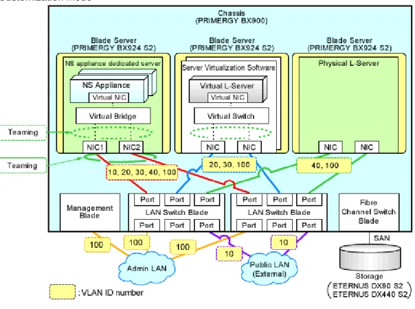
2.1.3.1 When Performing Auto-configuration Using User Customization Mode
For public networks that require auto-configuration or pre-configuration, decide the public LAN IP address, VLAN ID, and routing information.
The L-Platform network environment when performing auto-configuration using user customization mode is explained below.
Figure 2.4 Scope Configured by the Auto-configuration Function when Performing Auto-configuration Using User
Customization Mode
Figure 2.5 Example Network Configuration of Blade Servers when Performing Auto-configuration Using User
Customization Mode
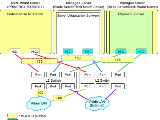
Figure 2.6 Example Network Configuration of Rack Mount Servers when Performing Auto-configuration Using
User Customization Mode
Information
The settings for internal connection ports of LAN switch blades, which are the network items to be protected by the security function of NS Appliance, need to be manually configured.
When creating an L-Platform using an L-Platform template, deployment of L-Servers triggers performance of the following network configuration:
-
Creation of Virtual NICs-
Creation of Virtual Switches-
VLAN Settings for LAN Switch BladesFor details, refer to "4.1.2 Configuring Settings for LAN Switch Blades" and "4.1.3 Configuring Settings for L2 Switches".
2.1.3.2 When Performing Auto-configuration Using Simple Configuration Mode
For public networks that require auto-configuration or pre-configuration, decide the public LAN IP address, VLAN ID, and routing information.
The L-Platform network environment when performing auto-configuration using simple configuration mode is explained below. For details on the network configuration and the information for design, refer to "Appendix I Auto-configuration and Operations of Network Devices Using Simple Configuration Mode" in the "Design Guide CE".