Megapixel IP Camera
User manual
2013.9.16 V2.0.0
Introduction
Productions are embedded system software and 38 special high definition IP camera modules, own compression, video data processing functions, are formed by video compression encoder, input and output channel, network interface, video interface, RS422 serial interface, protocol interface and software interface and so on, also offer video processing function, finish image data collection, H.264 image data compression, internet transmission data, transmit real time image through wired network.
Production adopts arithmetic speed more fast digital processing unit, compress size to get more clear image, use advanced operating system, video compression algorithms, let image transmission more smoothly and show more clearly, uses embedded server, break away from PC platform completely, system scheduling efficiency, code solidify in Flash, system running is stable and reliable. It supports remote image visit through Internet Explorer, support dynamic IP address, achieve image network transmission easily.
Features:
Support two channels video; two channels independently, 60 FPS activity video p er second.
H.264 video compression standard.
Embedded Web Server, support Internet Explore monitoring, configuration and u pdate.
Video frame can adjust owing to bandwidth.
Support variable bit rate, can restrict video image quality and compression bit stre am at the same time.
Support two level domain names; achieve dynamic IP address (ADSL dial). Video code rate can adjust continuously (50Kbps-8Mbps) and frame (1-25). Support snapshot, local recording.
Dynamic detection support (set area and sensitivity). Alarm pre-record function.
10/100M Ethernet interface support.
Support IO interface to connect other equipments.
RS485 interface, network transparent channel connection, client can control RS485 through device’s transparent channel.
Support multi users visit at the same time.
Support OSD.
Support client remote monitor software. Support Platform.
Support mobile monitor. Support cross service.
Our suggestions to customer PC basic configuration as follow:
CPU four core 3.0GHz, 4G memory, 512 M independent video memory, 2.1 audio, audio output, Mic input, Windows2000/XP/2003/7, Microsoft IE 6.0~9.0.
The user manual is edited based on present issued software, there may be some inaccurate and incomplete places on user manual technology problem owing to software update, modify and upgrade, please understand our work. Our user manual will update periodically without notice.
CONTENT
INTRODUCTION ... 1
CONTENT ... 3
1 DEVICE AND INSTALLATION... 1
1.1 SPECIFICATIONS ... 1
1.2 APPEARANCE AND DIMENSION ... 2
1.3 DEVICE CONNECTION... 2
1.4 CONTROLS INSTALLATION ... 4
1.5 VIDEO BROWSING ... 6
2 NETWORK... 10
2.1 NETWORK STATUS ... 10
2.2 ETHERNET SETUP ... 10
2.3 WIFI SETUP ... 11
2.4 ADSL SETUP ... 14
2.5 DDNS SETUP ... 14
2.6 UPNP SETUP... 15
2.7 FTP ACCOUNT SETUP... 15
2.8 SMTP ACCOUNT SETUP ... 16
2.9 MEDIA STREAM SETUP... 17
2.10 PLATFORM SETUP... 17
2.11 PPTP SETUP... 17
3 MEDIA ... 19
3.1 VIDEO CAPTURE ... 19
3.2 TIME AND TITLE SETUP ... 20
3.3 VIDEO ENCODE ... 20
3.4 PICTURE CAPTURE ... 22
3.5 PRIVACY MASK ... 22
3.6 MEDIA INFO... 22
4 STORAGE... 24
4.1 STORAGE MANAGE ... 24
4.1.1 UNINSTALL OF STORAGE DEVICE... 24
4.1.2 FORMATTING OF STORAGE DEVICE ... 24
4.2 STORAGE SETTING ... 25
4.2.1 BASIC SETUP ... 25
4.2.2 MOTION ALARM RECORD ... 25
4.2.3 MOTION ALARM SNAP ... 26
4.2.5 LINK DOWN CAPTURE... 28
4.2.6 SCHEDULE RECORD... 28
4.3 STORAGE DEVICE INFORMATION ... 30
5 ALARM ... 31
5.1 MOTION ALARM... 31
5.2 VIDEO LOST ALARM ... 32
5.3 STORAGE FULL ALARM ... 33
6 SYSTEM SETUP... 34
6.1 ACCOUNT MANAGE ... 34
6.1.1 ADD USER ... 34
6.1.2 MODIFY USER ... 35
6.1.3 DELETE USER... 35
6.2 TIME SETUP ... 36
6.3 LOG SETUP... 36
6.4 LOG FILE MANAGE ... 37
6.5 SYSTEM MAINTENANCE ... 37
6.6 REGULAR MAINTENANCE ... 40
6.7 DEVICES LANGUAGE ... 40
6.8 VERSION INFO ... 41
7 PLAYBACK ... 42
7.1 THE SEARCH OF FILE ... 42
7.2 PLAYBACK OF FILE ... 43
7.2.1 PLAYBACK OF RECORD FILE ... 43
7.2.2 PLAYBACK OF PICTURE... 44
7.3 THE DOWNLOAD OF FILE ... 45
7.4 THE DELETE OF FILE... 47
1 Device and installation
1.1 Specifications
Model 1.0MP 1.3MP
Embedded LINUX RTOS ,dual core 32 bits DSP (HI3518) System Structure
Pure hardware compression, watchdog, 16M Flash, 128M DDR3.
Image Sensor 1/4’’ 1.0 Megapixel CMOS Image sensor 1/3’’ 1.3 Megapixel CMOS Image sensor Lens Mount CS ( M12/M14/M20 optional )
Minimum Illumination [email protected] ( color), [email protected] (B/W) Photoresistance
Linkage
Support linkage between photoresistance input sign, image, IR-Cut and IR lamp. 1 photoresistance interface.
Day & Night IR cut filter with auto switch, IR sensor. 1 IR lamp control interface , algorithm control IR lamp open and close
Video compression H.264 compression ,dual stream ( 0.1M-6Mpbs adjustable) Frame Rate 30 FPS ( 1-30 FPS adjustable)
Main Stream:1280×720 Main Stream: 1280×960 1280×720 Image Output
Sub Stream: 640×360, 320×180
Alarm Function Motion detection and IO alarm linkage ip camera storage supported 1RJ45 Ethernet interface, 10/100M adaptation
Network Interface
Protocols : RTSP/FTP/PPPOE/DHCP/DDNS/NTP/UPnP
WEB configure and OSD supported, real time recording, transmission and playback, download. Network Function Free UC2 client software supported, VM6000 platform supported, SDK for customer software
development; POE/ optional
Lens Mount 4/6/8/12mm 1.0/1.3MegaPixel Lens
Power Supply DC12V±5%
1.2 Appearance and Dimension
1.3 Device connection
The connection schematic diagram for entire system frame of device is as figure 1.1. Connect the computer and device directly by switch or a network cable and configure network parameter as follow: First, the default IP address of device is 192.168.0.123, net mask is 255.255.255.0, accessing the device, you must make sure your computer and the device in the same network segment. If not, add a network segment for your computer. Second, the net mask of the computer and the device must be the same. Last, make sure the direct network is open, operating as follow: “Start”-“Run”-enter “cmd”, then enter “ping 192.168.0.123” and press “enter” on the keyboard. As figure 1.3, 1.4, and1.5. While the network is not open, please check the network connection and the network configuration.
Figure1.1 network connection diagram
Figure1.2 enter “cmd”
Figure1.4 network is open
Figure 1.5 network is not open
1.4 Controls installation
After connected device and finished configuration network parameter, connect the power, one minute later, open the IE browser, and enter IP address, press “Enter”, then come out the login interface as figure 1.9. If this is the first time to access device by browser, it will prompt that you need install controls first. Steps are as follows: a. After entering IP address, maybe come out the interface as figure1.6, this is
because our controls has not legalized by IE, but it makes no difference. Click
Figure 1.6 Security Warning
b. Then come out the message says that: “Please install the plug!”.
Figure 1.7 Please install the plug
c. After that, you will see the interface of controls’ installation, of course, different browser version has different interface. If there is no the interface of figure 1.8, look down, in the bottom of the browser, there is a line of writing says that: “Please install the plug!”, click it, with the same function that it will link to the interface of controls’ installation.
Figure 1.8 controls installation interface
d. According prompt message to install controls step by step. It should be noted that, during installation, you must close all browser windows, otherwise the installation maybe failure.
Figure 1.9 the login interface of device
Notice:
1. During the installation of controls, because different browser versions may be different interfaces, users need install according prompt message. Some antivirus software may prompt there are security risks, this because our controls have not do safety certification, but in fact there is no security risk. Those prompt messages can be ignored.
2. Before the installation of controls, you must close all browser windows.If there is more than one installation is unsuccessful, it is recommended to clear your browser's cache and then re-install.
In the login interface, enter correct username and password, the default username and password of IPC are “admin” and “123456”. After correct entering, click the button of “Login”, then you can login successfully. In the login interface, there is a link to install controls and you can choose interface language also. There are five languages can choose, they are Simplified Chinese, Traditional Chinese, English, Russian and Turkish language.
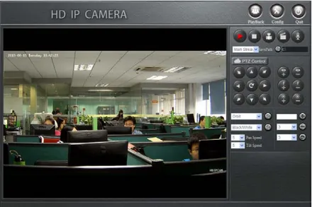
1.5 Video browsing
After successful login, you will enter the interface of video browsing.
Figure 1.10 the interface of video browsing
The video browsing interface is made up of three parts: the function button located at the top of the zone, the video window located at the lower left and the PTZ control panel area located at the lower right.
a. The function button area: include three buttons: Playback, Config and Quit. Click the button of Playback, this camera with storage device, then come out playback interface, otherwise notice you the camera has not connected storage device. Click the button of Config then come out the interface of config. Click the button of Quit then you will login out.
b. Video-play window: when you are playing real-time stream, you can choose playing sub-stream or main- stream by yourself. And double-click the window the video will play in full screen.
c. PTZ control panel:
Play Video: when the middle triangle is red, means there is video stream; when is white, means there is no stream.
Stop Play: clicking this button, video will stop and clear window.
Snap Picture: clicking this button, will take photos of the current video screen. Pictures default saved in the path of C disk, and creates a new folder which name is today’ date. Of course, the save path can be modified by yourself.
Record: clicking this button, device will record. Button flicker means recording. Records default saved in the path of C disk, and creates a new folder which name is today’ date. Of course, the save path can be modified by yourself. It should be noticed
that when the free space is less than 2G, you can not record.
Voice: if this device with the function of audio and opened it, click this button, you can talk between PC and device. Button flicker means in the talk.
Stream setting: this button is to set that the video window is play main stream or sub stream.
Save Path: to configure the save path of snap picture and record. If snap pictures or records, system will auto-create a new folder which name is current date in the setting path. It should be noticed that the setting path will not saved if you login out. PTZ direction control: connect to the PTZ, you can control it to turn up, down, left, right, left up, right up, left down, right down and auto.
Zoom In: zoom focal length. Zoom Out: pull away focal length. Focus Far: increase focal length. Focus Near: shorten focal length.
Iris Open: enlarge iris, the larger iris, the brighter screen. Iris Close: reduce iris.
Figure 1.11 the setting of orbit/scan function
Orbit: Select “Orbit” and click “Run” then the PTZ will turn among all preset number.
Stop Orbit: Select “Orbit Stop” and click “Run” to stop orbit.
Scan Start Point: Turn lens and select “Scan Start Point” in the “Orbit/Scan List” and click “Run”, then this point is “Scan Start Point”
Scan Stop Point: Turn lens again and select “Scan Stop Point” in the “Orbit/Scan List” and click “Run”, then this point is “Scan Stop Point”
Start Scan: When the “Scan Start Point” and “Scan Stop Point” is done, then select “Start Scan” in the “Orbit/Scan List”, and then the lens will turn between this two points.
Stop Scan: While the “Start Scan” is running, select “Stop Scan” to stop.
Figure 1.12 preset related operations
Add preset: the preset number range from 1 to 255, first turn lens and enter preset number, click the button of “+”, then add preset successfully. The preset number from 1 to 64 can be deleted or called, 65 to 255 can not be deleted but can be called by manually entering.
Delete preset: select a preset number to be deleted from the option box and click “-” bottom.
Call preset: select a preset number from the option box and click “ ” then the lens will turn to the preset point location.
Figure 1.13 PTZ advanced function
Advanced Function: Includes “Black/White”, ”Color”, ”Mirror Off/On”, “Freeze Off/On”, “Steps Off /On”, “Screen Off/On”, “Lumen Off/On”, “ILL Off/On”, “Camera Reset/Switch”, “B/W Auto”, “WB R/G/B/M”, “Initial Set”, “Menu”, “Track Off/On”, “Path On/Off” and so on.
For example, for “Black/White” and “Color”: we can see the preset number of “Black/White” and “Color” is 64, but “Black/White” is “Set preset” and “Color” is “Call preset”. The work of the advanced function is “set preset” and “call preset”. So select “Black/White”, it will play in black/white mode, while select “Color” it will play in color mode.
All the functions are same with them, but different camera with difference, please refer to the corresponding user manual of camera.
Speed: when turns, the speed ranges from 0 to 10, Data larger and speed faster. It should be noticed that if you change interface or login out, the modified speed will not saved.
In the main interface click the button of “Config”, will come out the dialog of “Remote Config”. Then you can configure the parameter of Network, Media, PTZ, Storage, Alarm, system and so on.
2 Network
2.1 Network Status
Click [Network]-[Network Status], it will display interface as figure 2.1. In this interface you can view the information such as MAC Address, IP type, IP address, Gateway, Net Mask and DNS and so on. The detail information please refers to the actual configuration.
Figure 2.1 Network status
Notice:
When enable WIFI, this interface will show the connection status of it.
2.2 Ethernet Setup
[Ethernet Setup] is to set network parameter of this device. The setup parameter will show in the interface of [Network Status].
MAC Address is hardware address of device. If not must please don’t change. You can only save the legitimate and correct MAC address.
When you access the device you need use its IP address. Here, you can enter a new address to change it. Also, you can modify the IP address by IP search software or other tools. Make sure the IP address of device and IP address of your PC are in the same network segment, but not the same. After reset IP address the device will reboot, then use the new IP address to access the T38R/R2 device.
Net mask matches with IP address to distinguish network address and local address, usually set it as 255.255.255.0. The correct net mask is the premise for saving it. Gate way is point between two networks such as router. So you can enter the router IP
address. The gateway and IP address must in the same network segment.
DNS server address is the host IP address running in the domain server, which provide by network operators. When you don’t know how to set it, you can search in the internet, or you can enter 8.8.8.8 which is common used in the world.
DHCP is a network protocol in local area network. Enable DHCP function device can obtain IP address automatically in local area network. But achieve this function must ensure your router enables DHCP function also.
Figure 2.2 Ethernet setup
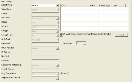
2.3 WIFI Setup
WIFI setup as figure 2.3, First you need to set wireless router called AP for short.
Figure 2.3 WIFI setup
When set the WIFI network parameter of wireless router, such as TP-LINK (the type is TL-WR941N), first enter setup interface, enable wireless function and SSID broadcast, custom the SSID which is the name of this WIFI, choose wireless channel. WIFI mode usually choose 11n only or 11bgn mixed, also you can set by yourself;
Fill other parameters according to the actual situation.
The encryption of WIFI is to ensure security. Different router has different encryption methods. Please according to your own needs and the system prompt messages to set it.
After configured wireless router, we can start configure the WIFI parameter of device. Enter the interface of [WIFI Setup], there are four function areas: AP search, WIFI config, WIFI network and ping watch dog.
The interface of AP search as figure 2.4, click the button of “search”, device will auto-search available WIFI access point in local network and show in the list, as figure 2.5. This list detailed shows SSID, quality, encrypt type, level and other information of each AP, user could make a choice through those parameters. Double click will automatically fill AP information into WIFI configuration list.
Figure 2.4 AP search interface
Figure 2.5 AP information list
Figure 2.6 click AP, automatically fill information
The interface of WIFI Config as figure 2.7, when use the function of AP search, double-clicking can auto add the configuration of WIFI parameter, but if the AP you added enable encrypt, you need enter the right password.
You can also manually enter the information to add AP. First enable WIFI function. Values of ESSID, MAC mode, region, bit rate and encryption-related information please according to the setting of wireless router.
Figure 2.7 the interface of WIFI configuration
When device connects with WIFI and without wired network, you can access it by wireless IP address. Manual set or use DHCP function can get wireless IP address. When enable DHCP, the wireless router must enable DHCP too, otherwise the device can’t get IP address.
Figure 2.8 the configuration of WIFI network
To avoid device drops in the case of abnormal, we can enable the function of ping watch dog. Right fill ping IP address, ping time interval, ping maximum timeout and save, then during the operation of the device, it will every time interval ping IP address once, if request timed out, the timer add one, otherwise, set to 0. If the value of timer bigger than maximum timeout, device will reboot automatic.
Figure 2.9 ping watch dog configuration
Notice:
Only when the device is properly connected with a WIFI module, you can see [WIFI Setup].
2.4 ADSL Setup
ADSL setup is as figure 2.10.The username and password of the ADSL are provided by network operators, enter correct username and password, enable ADSL and save it. We can’t judge username and password if right when save, but only right username and right password can dial successfully.
Figure 2.10 ADSL Setup
2.5 DDNS Setup
DDNS setup is as figure 2.11.First you must have a domain name. www.3322.org is recommended; please remember
the username, password and domain name.
Then enable DDNS, select the DDNS Server as “3322.org”. If your domain name is “test.3322.org”, please enter “test” in the DDNS Domain, and the User Name and Password is the username and password that applied in the www.3322.org. Set the Refresh Time as 1 minute, then DDNS will work after 1 minute.
Last you can access the device by domain name.
Figure 2.11 DDNS Setup
2.6 UPNP Setup
UPNP setup is as Figure 2.12.Usually, when device accesses the internet, if not in an independent network, it need port mapping. That is to say, we need map a device’s media access port, PTZ control port and web access port in router, after that we can access this device in the internet. In my mind, these operations are very complex. But when enable UPNP, just enter the IP address of router add this device’s web access port, you can access this device in the internet.
Figure 2.12 UPNP Setup
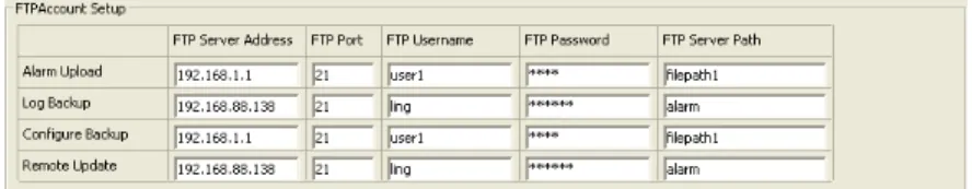
2.7 FTP Account Setup
FTP account setup is as Figure 2.13.First a FTP server is indeed. Then apply a FTP account from the FTP server (username and password). And you must create four directory as “alarm”, “log”, “set”, “update” or other directory name, also you can enter “./” then the entire document will be save in the root of the FTP server.
The default port of FTP is 21. The information of the interface must be correct to make sure the FTP function run correct.
Alarm upload, log backup, configure backup and update can be uploaded by FTP.
Figure 2.13 FTP Account Setup
2.8 SMTP Account Setup
SMTP account setup is as figure 2.14.This function not only support internal mail transfer but also internet.
SMTP Server Address is refers the IP address of mail server, such as QQ is smtp.qq.com, NetEase,Inc is smtp.163.com.
SMTP Server Port usually set as the default port 25.
SSL/TLS connect is a mode to verity security. When SMTP server enables this function here must enable, otherwise the same.
Mail Account is a user or to say an address in SMTP servers. You must enter a correct account and the correct password.
Show Account is the same as Mail account.
User Mail Address is the mail address that you want to receive the mail. SMTP Server Address and User Mail Address, if former is internal the latter must internal, otherwise if former is internet the latter must internet too. CC Mail Address is means when the device set mail to User Mail Address, it will copy the mail and set to CC Mail Address. CC Mail Address has the same rule with User Mail Address.
Mail Subject is the subject of the mail, you can write it by yourself.
Figure 2.14 SMTP Account Setup
2.9 Media Stream Setup
Media Stream Setup is as figure 2.15.Access Protocol: while the device is in public network, TCP is a better choose, while the device and the user are the same network then UDP is a better choose.
The default WEB port is 80. You can change it at will. But if you change it as 8080, then you enter 192.168.0.123:8080 for accessing the device.
All the port in the interface can change at will but can not be the same or the used port such as 3000, 8888. When you do not want to set the port as default port them must bigger than 1000. Only when the three ports set legitimate value you can normally access the device.
Figure 2.15 Media Stream Setup
2.10 Platform Setup
Platform Setup is as figure 2.16.Figure 2.16 Platform Setup
The device can login platform server on the premise that the server IP and Server port is corresponding to the server. The server account and password can enter them wt will. Of course enable login server is indeed.
Figure 2.17 PPTP Setup
PPTP is a multi-protocol network technology for virtual private network. When need access, enable it first, then right enter the access server IP, access server account and access server password, last save. When information is correct will achieve this function.
3 Media
3.1 Video Capture
Video Capture includes two sides: IRCUT setting and video Capture Setup.
IRCUT has five work modes: active mode, day and night, passive, manual and inverse passive.
The working principle of active mode is that it use module to set control signal to control light board, according light intensity auto switch color and black/white mode; day and night mode is by setting night start time and night end time, after enabled, during the time video always in black/white mode; passive mode use level control signal that send from light board to control the switch of module IRCUT; manual mode is to switch day or night mode manual. The principle of inverse passive is the same with passive, but has opposite result.
The function of “Keep color” means even if in black/night mode the video also colorful. “Sensitivity” is only function in active mode.
Figure 3.1 IRCUT setting
Video capture setup include “Brightness”, “Saturation”, “Sharpness” , “Contrast”, “Backlight Control” and so on , different country with different “Video Format”, in China just PAL format.
Figure 3.2 Video Capture Setup
You can enter number to set the parameter of “Brightness”, “Saturation”, “Sharpness”, “Contrast” and “Backlight Control”; also click “default” is a good method. High “Saturation” means color is more obvious; High “Contrast” means the effect is more obvious. All the parameters must according to the physical environment.
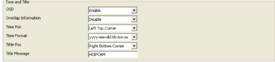
3.2 Time and Title Setup
As we know, time and title are displayed in the video window. When disable it, the OSD information will be hidden.
Overlap information is to set if display the resolution or bit rate information or not. There are four options: “Disable” means don’t display, “Resolution” means display the resolution information only, “Bit rate” means display the bit rate information only, “Resolution and Bit rate” means both display. You can set by yourself.
There are 8 time format, you can choose under preference.
There are 4 time/title positions, time and title display position to be in a different horizontal position.
The max length of the title message is 31 byte. Do not forget to save it!
Figure 3.3 time and title
3.3 Video Encode
Video encode includes two sides: Video Encode Parameter Setup and Video Encode Advanced Parameter Setup.
Video has two streams, one is main stream another is sub stream, the encode format of both are H.264.
Main stream of T38R/R2 has three resolution, they are 720P, D1, VGA. The default value is 720P. Users could set it as their demand. Sub stream has ten resolutions to set.
the quietly of video. When the network bandwidth is stable, you can choose constants bit rate (called CBR for short). The third method is called CVBR, it give priority to CBR and compatible with VBR. So you should choose control method according to the network environment.
I frame is the key frame in video encode. In a bad network bandwidth environment, if I frame interval is too big, the quality of the video will be poor, even can not receive real video. In a good environment, there is no limit to set it. A good setting you can get by previewing the setting effect.
High frame rate means more fluent video. Low frame rate may cause picture update slow and bad interactive sense, so the suggestion setting is higher than 20.
Bit rate related to the speed of network transmission, that is to say how many kb information it could transfer every second. Because the resolution of main stream is times than sub stream, the date information need transferred in per second more, so need bigger bit rate. When the resolution is 1080P, the “Bit rate” at least 6000 kbps and when the resolution is QVGA, the “Bit rate” at least 300 kbps. The bit rate is too small result in poor image. Do not forget to save it!
Figure3.4 Video Encode
Base profile: when device need access some manufacturers supporting embedded NVR, you must enable base profile. But if enabled it, the video maybe with the problem of update slowly, so, if not must, it suggested disabled.
Private date: When the video is not smooth, enable it will make this problem be improved.
Figure 3.5 video encode advanced parameter setup
User could click the button of “default” to set all parameter as default value, only after click “save” you can save your setting.
3.4 Picture Capture
In this interface, “Picture Source”, “Picture Quality” and “Capture Speed” need to be set. Of course, the default parameter is another way.
Figure 3.6 Picture Capture
Picture source include “Main Stream” and “Sub Stream”; Picture quality range from 20 to 100, you also can drag the slider; Capture speed between 1 and 2, means 1 or 2 pictures per second.
3.5 Privacy Mask
If you hope that some areas in the video to be hided you can set privacy mask area. You can respectively configure four privacy mask areas for main stream and sub stream. Every privacy mask area is determined by four coordinate values. The area being privacy areas will be black screen whether in real-time stream or in record.
Figure 3.7 privacy mask setting
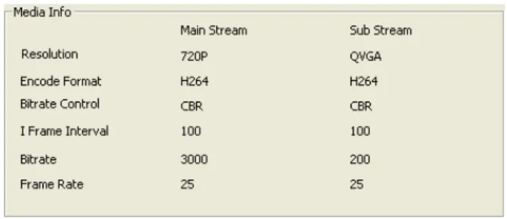
3.6 Media Info
In this interface, the main duty is display the status of video encodes.
4 Storage
4.1 Storage Manage
4.1.1 Uninstall of storage device
“Uninstall” means remove the storage from the device with a safe way, in order to prevent data been destruct. Choose the storage device that you want to uninstall, click the button of “uninstall”, it will pop-up a dialog as figure 4.2. Click “OK” it will uninstall this storage device. Once uninstall a storage device, it will stop using. When need use it again, you can restart the camera.
Figure 4.1 Storage Information
Figure 4.2 if ensure to uninstall storage device?
4.1.2 Formatting of storage device
lose and can’t restoration, so if there is some important date you’d better transfer it to other place.
Figure 4.3 if ensure to format storage device?
4.2 Storage setting
4.2.1 Basic Setup
The basic setup of storage setting is as figure 4.4.
Figure 4.4 basic setup
Local Storage: here must set “enable” then the device can record and snap.
Storage Strategy: the treatment when the storage space is not enough. It has two choices: shop record when the storage space is full or overwrite the old record when it full.
Storage media: to select the storage order of storage devices. A camera could connect three storage devices at all, they are SD1, SD2 and USB, so there are seven choices include the choice of auto select. You can select the order by yourself.
Max Time each file: when the configuration is schedule record, it refers to the record time of each record file. There are three choices. To limit record time can avoid too large record may open slowly or can not playback.
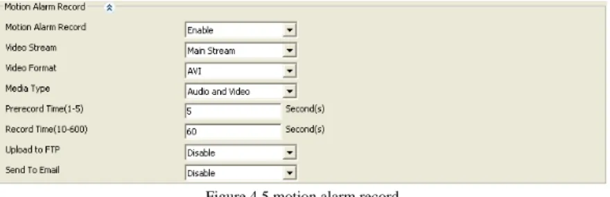
4.2.2 Motion Alarm Record
The setting of motion alarm record is as figure 4.5. Once enable this function, when there is motion alarm, the device will record according to the configuration.
Figure 4.5 motion alarm record
Motion alarm record: only when it enables others parameters can be changed. Video stream: there are two choices “Main Stream” and “Sub Stream”. Main stream has clearer stream, but record same time needs more storage space, so you can choice by your needing.
Video format: you can just choose AVI.
Media type: “Audio and Video” means the record file you will get with sound, so video without sound. But this not means that you choose “Audio and video”, you will get record file with sound. The premise is that your camera with the function of audio and there is audio input, moreover, the camera has enable the function of audio encode.
Prerecord time: before start record, camera saves date in temporary buffer, once start record, then call those dates, this is the function of pre-record. The most prerecord time our camera supports is 5 seconds.
Record time: time of a record file, range from 10 seconds to 600 seconds.
Upload to FTP: when you have right configured parameter of FTP, enable this function, when end record, camera will send this record file to server.
Send to Email: when you have right configured parameter of SMTP, enable this function, when end record, camera will send this record to the mailbox.
4.2.3 Motion Alarm Snap
When there is motion alarm, if the storage space is not enough or you need not record, but you need know what cause this alarm, you can choose the function of motion alarm snap. Enable this function, when there is motion alarm, camera will snap picture according to the configuration.
Figure 4.6 motion alarm snap
Motion Alarm Snap: only when it enables others parameters can be changed. Pre-capture time: before start snap, camera saves date in temporary buffer. Once start snap, then call those dates, this is the function of pre-capture. The most pre-capture time our camera supports is 5 seconds.
Capture time: time of a snap picture, usually one second one picture.
Upload to FTP: when you have right configured parameter of FTP, enable this function, when end snap, camera will send this picture to server.
Send to Email: when you have right configured parameter of SMTP, enable this function, when end snap, camera will send this picture to the mailbox.
It should be noticed that, when you enable motion alarm snap, want to get picture, you must enable the function of picture capture first. Enter the interface of [Media] - [Picture Capture], ensure “Snap Picture” is enabled, others parameters please refer to section 3.4
Figure 4.7 picture capture
4.2.4 Link down record
Network camera achieves the function of surveillance by network, but sometime the network maybe disconnect because of human or un-human cause. To avoid lose important information during this time, the camera has the function of link down record.
Figure 4.8 link down record
Link down record: only when it enables others parameters can be changed.
Video stream: there are two choices “Main Stream” and “Sub Stream”. Main stream has clearer stream, but record same time needs more storage space, so you can choice by your needing.
Video format: you can just choose AVI.
Media type: “Audio and Video” means the record file you will get with sound, so video without sound. But this not means that you choose “Audio and video”, you will get record file with sound. The premise is that your camera with the function of audio and there is audio input, moreover, the camera has enable the function of audio encode.
Prerecord time: before start record, camera saves date in temporary buffer, once start record, then call those dates, this is the function of pre-record. The most prerecord time our camera supports is 5 seconds.
Record time: time of a record file, range from 10 seconds to 600 seconds.
4.2.5 Link down capture
When links down, if the storage space is not enough or you need not record, but you need view the video now, you can choose the function of link down capture. The configure interface of link down capture as figure 4.9. Enable this function, when links down, camera will capture picture according to the configuration.
Figure 4.9 link down capture
Link down capture: only when it enables others parameters can be changed.
Pre-capture time: before start snap, camera saves date in temporary buffer. Once start snap, then call those dates, this is the function of pre-capture. The most pre-capture time our camera supports is 5 seconds.
Capture time: time of a snap picture, usually one second one picture.
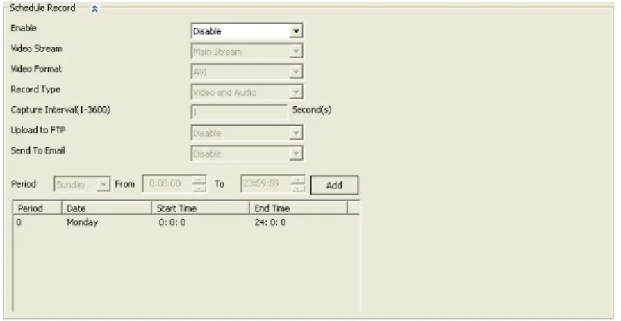
4.2.6 Schedule Record
Motion alarm record (snap) and IO alarm record (snap) is touched off relevant alarm, we call them alarm record. In addition, camera supports another form record (snap), it don’t need triggering condition, once enable, camera will record (snap) according to the configuration. We call it schedule record (snap).
It should be noticed that schedule record (snap) and schedule record can’t enable in the same time.
Figure4.10 schedule record
Enable: only when it enables others parameters can be changed.
Video stream: there are three choices “Main Stream”, “Sub Stream” and “snap picture”. When you choose “Main Stream” or “Sub Stream”, you will get record file, or you will got picture.
Video format: according the different video stream, there is different video format. Record type: “Audio and Video” means the record file you will get with sound, so video without sound. But this not means that you choose “Audio and video”, you will get record file with sound. The premise is that your camera with the function of audio and there is audio input, moreover, the camera has enable the function of audio encode.
Capture Interval: when the “Video stream” is “snap picture”, this option can set. It is to set how long device snaps a picture.
Upload to FTP: when the “Video stream” is “snap picture”, this option can set. When you have right configured parameter of FTP, enable this function, when end record, camera will send this record file to server.
Send to Email: when the “Video stream” is “snap picture”, this option can set. When you have right configured parameter of SMTP, enable this function, when end record, camera will send this record to the mailbox.
Record time setting: to set the time of schedule record (snap). It consists of date, start time and end time. After set a record time, click the button of “Add”, then this record time will show in below list. A camera can add twenty-four record time most. Once enable schedule record, during the setting time, device will record (snap) according to
1. The record or snap is the function of device that does not depend on network. So, once you enable record or snap, and set parameter in right way, when the device connects with power, it will record or snap according to the configuration. 2. If there is no storage device, camera can’t record.
3. If there is no storage device but enable snap picture, and enable “Upload to FTP” or “Send to Email”, if the configuration of FTP or SMTP is right, camera can snap picture and send to server or the mailbox.
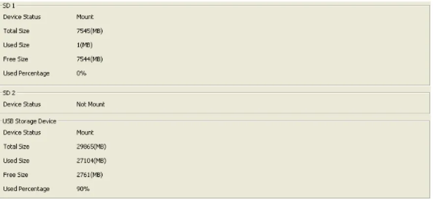
4.3 Storage device information
In the interface of storage device information, detail shows device status, total size, used size, free size and used percentage for every storage device.
Figure 4.11 the information of storage device
5 Alarm
5.1 Motion Alarm
The setting of motion alarm is as figure 5.1.
Figure 5.1 motion alarm
Motion alarm: only when it enables others parameters can be changed.
Sensitivity: the sensitivity of motion detection. The value is larger and more easily to create alarm.
Alarm threshold: to measure whether create alarm or not when the video changes. The value is smaller and more easily to create alarm.
Black count: to select the way to divide video. After divided, just the video change in the area that surrounded by red box will create motion alarm.
Enable night time: when the camera is working, maybe to the same video change, it needs different result in different time, this can be achieved by the function of “Enable night time”. Once enable it, during the setting time, night parameter makes function. If there is a conflict between standard time and night time, night parameter is first. Night start time: the start time that night parameter makes function.
Night end time: the end time that night parameter makes function. Night sensitivity: the sensitivity of night parameter.
Night alarm threshold: the alarm threshold of night parameter.
After set related parameter of motion detection, you need set alarm time, this function can be achieved by motion detect alarm schedule, as figure 5.2.
Figure 5.2 motion detect alarm schedule
The period number is auto create. A period consists of date, start time and end time. After set an alarm time, click the button of “Add”, then this alarm time will show in below list. A camera can add twenty-four alarm time most. The time among different period can not conflict, or can’t add successfully, as figure 5.3. You can’t modify a period, when the added time has question, you can delete it and add a new period. The deleting step is click this period, right-click the mouse, then come out an option of “Delete”, click it.
Figure 5.3 time conflict
Alarm output is another way for alarm. Enable “alarm output” and connect external device for output such as speaker, flash lamp Etc, to tell surveillance person that there is a motion alarm. Parameters you need to set as follows: enable alarm output or not, alarm output port, alarm output type and alarm duration. After set those parameters, click the button of “Save”, the setting will make function.
Figure 5.4 alarm output
5.2 Video Lost Alarm
Too many reasons can cause video lost, such as disconnect video cable. In this case,
parameters for it.
Figure 5.5 video lost alarm
5.3 Storage Full Alarm
If the camera with storage device, then you can enable “Storage Full Alarm”, it will alarm when the usage of the storage more than a value.
In this page, “Alarm Rate” is the usage rate of storage device. For example, we set it 95, it means that it will alarm when the use space more than 95%.
Storage full alarm has the same function of alarm output likes motion alarm, the interface as figure 5.6.
6 System Setup
6.1 Account Manage
In order to better manage device, we add functions of adding user, modifying user, deleting user and dividing different permission to different user.
Figure 6.1 account manage
6.1.1 Add user
Steps of adding a user as follows: first select “Add User”; Second enter the username, password and confirm password; Third select the user group and user status; Last click the button of “Save”, then add a user successfully.
Figure 6.2 add user
When add user the username and password can’t be null, and the password and confirm password must be the same. User group is to limit user privilege:
administrator without any limit; Operator can change configuration information but can’t view device status information; Viewer has instead permission of operator. User status is to set the effectiveness of user, when enable, the added user can login successfully, or can’t login.
6.1.2 Modify user
When need modify the information of a user, we can use the function of modify user. When modify user information, the username can’t be modified.
Figure 6.3 modify user
In the user list, click the modified user, the user information will show below, then select “Modify User”. The username displays gray, can’t be modified. You can modify others information, after modified, click the button of “Save”, then user information modified successfully.
6.1.3 Delete user
When a user no longer use, we can delete it. Select “Delete User”, you can achieve this function. It should be noticed that when delete user, you can’t delete the user that are logging, that is to say, you can’t delete yourself.
Figure 6.4 delete user
In the user list, click the user that needs to be deleted, the user information will show below, then select “Delete user”. Click the button of “Save”, the user will be deleted. Deleted user will no longer show in user list, and can’t use its username and password login device.
6.2 Time Setup
There are two types of update mode in this system. One is “Manual”, another is “NTP Server”.
NTP server is a protocol that syncs the time of device. It can make device synchronization with the server or clock source, which can provide high precision time correction. Select “NTP Server”, right set the device’s time zone, the IP address of NTP server, the port of NTP server, random set “Refresh Time”, after saved device will with the function of time synchronization. It should be noticed that, the default configuration of NTP Synchronization is use network to achieve this function, so you must ensure the device can connect to internet first.
Figure 6.5 the interface of NTP time setting
Manual is means that enter year, month, day, hour, minute, second and saved, then the device’s time is manually entered time. When select “Manual”, there is a function named “Synchronize with the Local Time”, select it will make the device time syncing your PC time.
Figure 6.6 the interface of manual time setting
6.3 Log Setup
Log is operation record during device is running. The output log type that device supports are “Debug”, “Run”, “Error”, “Operation”, “Alarm”, “Statistic” and “Common”, you can select according to actual needing.
Save day means a log file can save for how many days, once set, when the log file saved bigger than this value, it will be deleted.
Storage strategy is to select when the storage space is full, device deletes the oldest
Figure 6.7 System Log Setup
6.4 Log File Manage
Device supports query, download and delete function of log file.
Clicking the button of “Query” can query all log file in this device, and will show in the above list.
Select one or more log file, click the “Download” button, those log file will download to local computer. You can change the save path by yourself, but once you login out the setting will not be saved.
Select one or more log file, click the “Delete” button, those log file will be deleted. After deleted, log file can not recover.
Figure 6.8 log file manage
6.5 System Maintenance
The interface of system maintenance has three parts: configuration file manage, system update and system restore.
The interface of configuration file manage is as figure 6.9, it supports the function of uploading and downloading configuration file.
Figure 6.9 configuration file manage
When upload configuration file, you need select a file from local computer. While uploading, device will judge the format of this file, when the format matches, system will prompt as figure 6.10. If you click the button of “OK”, then begin uploading and overwriting configuration. After that, device will auto restart. The whole process lasts about one minute, during this time, please do not cut off the power of device. When the format not match, system will prompt as figure 6.11, because now just judges the file name not file content, so if you are sure the selected file is configuration file, you can click “OK” to continue. This step system will judge the content of your file, if in fact it’s a configuration file, it will upload success, or come out the prompt as figure 6.12.
Figure 6.10 if be sure to upload configuration?
Figure 6.11 the file format not match
Figure 6.12 the file format error
When download configuration file, you need set “Save Path” first. System default path is “C:\”, when you need change it, click the button of “Loading”, and select a path in your local computer. After setting the save path, click “Download” button, then can achieve the configuration file download function.
The interface of “System Update” is as figure 6.13. Click “Loading” button, jump to local computer, select a firmware file that needs to update, as figure 6.14, click the button of “Open”, then the file path auto written in the text box which behinds the “Firmware File”, click “Upgrade” button, update beginning. The firmware update include three stages: First is the upload of firmware file, as figure 6.15; Then is firmware upgrade, while this step, system will countdown; Last is device restart, after restart system will auto jump to the interface of login. From begin to end, it about continues two minutes, during this time, please do not cut off the power of device.
Figure 6.13 system update
TH38C
firmware_TH38C-ONVIF-V2.5.0.6_20140325180316.binTH38R
firmware_TH38R4-ONVIF-V2.5.0.6_20140325175914.binFigure 6.14 select the firmware file
Figure 6.15 firmware file uploading
The interface of “System Restore” is as figure 6.16. It includes two functions: factory default setting and reboot. If device recover to factory default setting, the current configuration information such as IP address, video parameter etc, will recover to default and can not regain again, so before you use this function, please think carefully.
System reboot will stop all processes of device, after rebooting, system will jump to the interface of login.
Figure 6.16 System restore interface
Figure 6.17 are you sure to restore the factory default setting?
6.6 Regular Maintenance
The function of “Regular Maintenance” can make device auto reboot in setting time. To achieve this function you need set maintenance date and maintenance time, you can set the device reboots every day or reboots one time in one week. The function of regular maintenance can make device initializing some functions when device running too long. And it can extend device using life.
Figure 6.18 regular maintenance
6.7 Devices Language
This version supports five languages: Simplified Chinese, Traditional Chinese, English, Russian and Turkish language. Select the language you need, click the button of “save”, then set language successfully. After that, system will auto jump to login interface. When you access this device again, the login interface is the language here you set.
Figure 6.19 Device Language setting
6.8 Version Info
In this interface you can view kernel version, file system version, serial number and web control version.
7 Playback
When device connects with storage device, click the button of “playback” in the main interface, it will come out a dialog of “Record file play back”, as figure 7.1. In this interface, we can do operations as search, playback, download and delete for record files or snap pictures. If there is no storage device, it will prompt as figure 7.2.
Figure 7.1 playback interface
Figure 7.2 the device without storage device
7.1 The search of file
When search file, you need set the searching conditions first, as figure7.3. File search conditions include “Record type”, “Media type”, “Stream type”, “Start time” and “End time”.
Record type divides according to the trigger condition of files. They are motion,
schedule and alarm.
Media type includes audio and video, only video and picture. The type of “audio and video” with audio date when it record, if the device with audio input, it will with sound when playback.
Stream type include main stream and sub stream. When “Media type” selects “Sound”, this button can’t be selected.
The start time and end time are to limit searching time, the default value is from zero to now time, and this time reference local computer. Because when record or snap pictures, the time reference device time, if the time of device and the time of local computer are not the same, you need enter the right time range to search, or maybe you can’t search any file.
Figure 7.3 the setting of file search
After setting search conditions, click “Search” button, the device will search according the setting. While search, there are text prompt search progress below playback window. Search over, the search result will show in the right list, as figure 7.4.
Figure 7.4 search result
7.2 Playback of file
7.2.1 Playback of record file
After searched some video file, select one or more, click the box that in front of those video file, video file playing button will show below the playing window, as figure 7.5.
Figure 7.5 record file playing buttons
Click the button of “Play”, then begin playback video file. During this time, the button changes to “Pause”. When playing video file, double click the window, video will display in full screen.
Clicking the button of “Stop” will stop the playing, the window recovers to black. Click the button of “Fast”, video will play in the speed of N times than normal speed, times are 2X, 4X, 8X, 16X, 32X, user can set according to their actual needing. Click the button of “Slow”, video will play in the speed of 1/N times than normal speed, times are 1/2X, 1/4X, 1/8X, 1/16X, 1/32X, user can set according their actual needing.
When playing video file, you can select more than one file, during playback, when a video is over, then will auto skip to the next. The name of playing video file shows in the right side of playback button.
Figure 7.6 the playback of video file
7.2.2 Playback of picture
After searched some pictures, select one or more, click the box that in front of those pictures, pictures playing button will show below the playing window, as figure 7.7.
Click the button of “Play”, picture will show in the playback window. Double click the window, picture will display in full screen.
If select more than one picture, you can switch pictures by buttons of “Previous” and “Next”, button switches just limit in the selected pictures. When the playing picture is the first one in selected, even there are many unselect pictures above it, now click “Previous”, will come out the tips as figure 7.8; contrary, when the playing picture is the last one in selected, will come out the tips as figure 7.9.
Figure 7.8 is the first picture
Figure 7.9 is the last picture
When playing picture, device needs link its address first, and download picture date, then you can view this picture. If the network is not good, this process will spend much time. When a picture played one time, system will save it date into local computer, when play this picture again, system will read local date no longer need by network. This function is achieved by cache. In this way, we can view picture faster. Click “cache” button, you can set the cache path in local computer.
Figure 7.10 download file
When you need download video files or snap pictures to local computer, you can use the function of “Download”.
After searched files, select one or more, click the button of “Download”, come out the dialog as figure 7.10. To achieve the function of download, you must select files first, or will come out the dialog as figure 7.11.
Figure 7.11 the tips when select no file
Before download, you need set the save path first, the default path is “C:\”. After set, click the button of “Download”, file will begin downloading. During this process, you can’t change the save path. And now the button changes into “Stop”, if you click it, the downloading will stop.
Figure 7.12 downloading video file
Figure 7.13 download complete
7.4 The delete of file
When you don’t need a file, you can delete it. select the file that need deleted, click the button of “Delete”, then come out the dialog as figure 7.14, click “OK”, the selected file will be deleted. Once delete, the file can’t recover, so you need think carefully.