Compression End
Series User Manual
Pneumatically, Electrically and Manually Actuated Ball Valves
This User Manual covers Gemini’s Models; A500 Pneumatic Actuators, 600 Electric Actuators, and 82 Ball Valves. The publication of these instructions are intended as a guide only. Installation should only be performed by qualifi ed personnel. Additional support is also available by contacting Gemini Valve @ Telephone: 603 244-7931, Email: [email protected].
Contents
SL14-1807Ball Valve Model 82
2. Installation / Specifi cations 3. Specifi cations (continued) 4. Maintenance
Pneumatic Actuator Models A500
5. Installation
6. Installation
(continued)7. Specifi cations / Operation / Maintenance
Pneumatic Actuator Accessory - Solenoid Model GP
8. Installation 3GP 9. Installation 4GP
10. Specifi cations / Maintenance
Pneumatic Actuator Accessory - Limit Switch Model LS-1
11. Installation
12. Wiring / Specifi cations / Maintenance
Electric Actuator Models 600
13. Installation
14. Wiring AC Models 15. Wiring DC Models
16. Manual Override Handle Operation 17. Specifi cations / Maintenance
2 Otter Court, Raymond, NH 03077 USA
Model 82 Ball Valve
Installation
Note: If the ball valve you are installing is equipped with an actuator, the actuator can be dismounted from the ball valve if desired to facilitate ease of installation. For further instructions see associated Pneumatic Actuator Models A500, Installation, Page 6, Actuator Removal for Ball Valve Installationor, Electric Actuator Models 600, Installation, Page 13, Actuator Removal for Ball Valve Installation. Tube (initial assembly):
1. Ensure the tube end is square and free from burrs, nicks, scratches and debris.
2. Loosen the NUT by turning it counter-clockwise one turn. Insert the tube through the NUT and FERRULES until it sits against the internal VALVE SHOULDER. Tighten the NUT (clock-wise) hand tight. Continue tightening the NUT with a wrench for 1 to 1-1/4 turns or until snug.
Note: for re-assembly, after initial assembly, approximately 1/4 turn with wrench is generally required to re-tighten.
Speci
fi
cations
TEMPERATURE*: -50°F to 450°F
VALVE BODY PRESSURE RATING*: 1,000 P.S.I**. C.W.P.*** MAXIMUM PRESSURE DIFFERENTIAL: 400 P.S.I.**
*see Differential Pressure - Temperature Chart **P.S.I. = Pounds Per Square Inch
***C.W.P. = Cold Working Pressure to 150°F VACUUM: 20 Micron
SATURATED STEAM: 150 P.S.I.
CONNECTION - STYLE: Tube Compression End
BODY DESIGN / SIZE RANGE: Two Piece Body - Standard Port 1/4” - 1” MATERIALS:
BODY;
Brass - ASTM B-16
316 Stainless Steel ASTM A276,
BALL AND STEM; 316 Stainless Steel - ASTM A276)
SEATS AND STEM SEAL; Glass Reinforced P.T.F.E. (Tefl on ®)
SHOWN: CORRECT ORIENTATION OF NUT & FERRULES
Model 82 Ball Valve
Speci
fi
cations
(continued)Cv
Note: The values derived from the fl ow equation are for estimating purposes only. Product variances or systemic factors may alter actual performance.
To Calculate Pressure Differential
Compare the Upstream media pressure to the Downstream. The pressure differential should not exceed 400 P.S.I. See examples below;
Examples:
Upstream Pressure of 1,000 P.S.I. less Down-stream of 625 P.S.I. equals 375 P.S.I. which is below 400 P.S.I. differential i.e. OK
Upstream Pressure of 600 P.S.I. Less Down-stream of 0 P.S.I. equals 600 P.S.I. which is above 400 P.S.I. differential - outside of ratings not recommended.
DIFFERENTIAL PRESSURE - TEMPERATURE
CHART
P.T.F.E. Glass Filled Reinforced Te
fl
on®
To Use the Pressure - Temperature Chart
Draw an imaginary line from your media Differential Pressure to your media Temperature to confi rm it falls within the valve rating.
Model 82
Maintenance
Typical ball valve designs will
fi
rst show signs of wear via media leakage at the stem seal.
Gem-ini’s Compression End Series Ball Valves feature a self compensating stem seal design which use a pair of Belleville Spring Washers that when energized (fl attened) maintains a preload (squeeze) of the stem seal to stem, providing an extended period of leak-tight service without any maintenance required. Depending on the application media, temperature, pressure and cycles, the stem seal may eventually wear to the point that the Belleville Spring Washers no longer can compensate for stem seal wear i.e. loosen (de-energize). Evidence of this can be seen by media seepage and eventually leakage from be-tween the top of the valve body and the bottom of the actuator bracket. Depending on the corrosive nature of the valve media, if left, damage to the valve and or actuator materials may require replace-ment of the complete assembly vs. simple maintenance or replacereplace-ment of the worn valve.In many cases, readjustment of the stem nut may enable the valve to be returned to service. The fol-lowing outlines the procedure to readjust the stem nut. If adjustment does not stop media leakage from the stem seal this would indicate the ball valve is worn out and in need of replacement. Please note that Gemini’s Pneumatic and Electric Actuators may provide service life for two or more ball valves during their life expectancy. Additionally, the cost of a replacement ball valve is a small portion of the overall actuated ball valve assembly.
Caution: Before attempting any adjustment, isolate the valve media from the valve being adjusted i.e. no media pressure should be present. Protective clothing and eye wear is recommended.
1. Prevent the stem from turn-ing as the nut is tightened by inserting a wooden or plas-tic dowel through the valve, or if the valve is in-line (service), hold the ‘fl ats’ of the stem then tighten the stem nut until the Belleville Spring Washers have just become fully compressed (fl attened). If a torque wrench is available refer to the Stem Nut Torque Table.
Although the stem nut may spin freely when fi rst tightened, the torque needed to contin-ue tightening will increase pro-gressively after the stem nut contacts the drive key and the Belleville Spring Washers begin to defl ect.
The torque required to tight-en further will increase sharp-ly once the Belleville Spring Washers have become fully fl at-tened. Tightening beyond this point should not be attempted
as damage to the stem seal will result.
2. The correct orientation of the stem nut to the drive key is shown in Figure 1; this orien-tation is necessary to permit engagement with the twelve-point socket in the actuator pin-ion driver.
In order to achieve the desired orientation, loosen the stem nut until the nut / drive key relation-ship corresponds to either ‘A’ or ‘B’ in Figure 1. This adjustment should require less than one-twelfth (1/12) turn of the nut.
Pneumatic Actuator Models A500
Installation
These instructions detail the procedure for installing a Gemini Model A500 Pneumatic Actuator on a drive-key equipped Gemini Valve Model 76, 86 or 96 Ball Valve.
Figure 3
Check / Adjust Bracket Locator Screws
Before assembly of the Actuator Bracket to the Actuator, confi rm the proper position of the tor Screws. The Actuator Bracket uses two Loca-tor Screws to align the valve body to the actuaLoca-tor bracket. See Table 1, Figure 1. Adjust if required.
Figure 1 Table 1
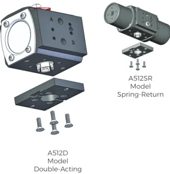
Assemble Bracket to Actuator
1. Position the actuator upright with driver and the A & B ports oriented as shown below, Figure 2.
2a: Standard Mounting: Inline
With the counter sunk holes exposed, position the bracket as shown. The bracket should be oriented perpendicular to the actuator body.
2b: Optional Mounting: Cross Mounted
With the counter sunk holes exposed, position the bracket 90° to that shown in Figure 1. The bracket should then be parallel to the actuator body.
3. Install the 4 hex fl at socket head mounting screws (Figure 2) to (60 inches lbs. to secure bracket to the actuator body. Important: To en-sure positive fastening mounting screws and bracket counter sunk holes must be clean and dry.
Assemble Valve to Actuator
Standard Mounting: Inline as shown below, Fig-ure 3.). Figure 2 A512D Model Double-Acting A512SR Model Spring-Return
Pneumatic Actuator Models A500
Installation
(continued)Standard Mounting: Inline (continued)
1. Confi rm the ball valve to be mounted has drive-key perpendicular to valve body meaning the ball valve is in closed position, Figure 4.
If it is not, rotate the ball valve stem using a wrench on the ‘fl ats’ of the stem.
2. Confi rm the red Actuator Position Indicator atop the actuator is perpendicular to Actuator Body (Figure 3). If it is not, rotate the actuator shaft us-ing a wrench on the ‘fl ats’ of the top output shaft. 3. Place the actuator with the bracket attached, atop the valve so that the 12 point socket of the actuator output shaft engages the ball valve stem and drive-key. The locator screws should straddle the valve body hex. Some valve models may re-quire the valve body be rotated 180°.
4. Slide the Retaining Strap over the valve and align with actuator bracket holes. Secure strap with two hex head cap screws. Alternate tighten-ing the strap bolts to obtain even tension on the strap and to avoid skewing. Do not over-tighten. A gap should remain between strap and bracket when assembly is complete.
Actuator Removal for Ball Valve Installation
In many cases it may be desirable to dismount the actuator from the ball valve for ease of ball valve installation. To do so simply loosen and re-move the two hex head cap screws (Figure 4) and re affi x following Instruction 4.
Figure 4
Optional: Cross Mounting
Standard build Double-Acting models can be cross mounted for both Normally Closed and Nor-mally Open operation. Standard build Spring-Re-turn Actuators can be cross mounted for Normally Open operation only. If cross mounted Normally Closed is desirable, purchase of model A512NOSR is required.
Normally Closed Operation (Double-Acting only) 1. Confi rm the ball valve to be mounted has drive-key perpendicular to valve body, meaning the ball valve is in closed position, Figure 4. If it is not, ro-tate the ball valve stem using a wrench on the ‘fl ats’ of the stem.
2. Confi rm the red Actuator Position Indicator atop the actuator is parallel to Actuator Body. If it is not, rotate the actuator shaft using a wrench on the ‘fl ats’ of the top output shaft.
Normally Open Operation
1a. Confi rm the ball valve to be mounted has drive-key parallel to valve body meaning the ball valve is in open position. If it is not, rotate the ball valve stem using a wrench on the ‘fl ats’ of the stem. 2a. Confi rm the red Actuator Position Indicator atop the actuator is perpendicular to Actuator Body. If it is not, rotate the actuator shaft using a wrench on the ‘fl ats’ of the top output shaft. 3. Place the actuator with the bracket attached, atop the valve so that the 12 point socket of the actuator output shaft engages the ball valve stem and drive-key. The locator screws should straddle the valve body hex. Some valve models may re-quire the valve body be rotated 180°.
4. Slide the Retaining Strap over the valve and align with actuator bracket holes. Secure strap with two hex head cap screws. Alternate tighten-ing the strap bolts to obtain even tension on the strap and to avoid skewing. Do not over-tighten. A gap should remain between strap and bracket when assembly is complete.
Pneumatic Actuator Models A500
Speci
fi
cations
TEMPERATURE: -20° F to 350° F
CYCLE (INDEX) TIME: Approximately 1/2-1 Second (Load Dependent)
AIR SUPPLY: 60 - 125 P.S.I. Suffi cient air delivery must be available at the actuator to ensure depend-able operation. The following precautions should be observed: Air supply should be clean and free of moisture. When dirty or wet air is a problem; a fi lter / separator should be specifi ed; these units are most effective when installed as close as possible to the actuator. A fi lter, when used, should permit a minimum fl ow of 4 scfm at an upstream pressure of 60 P.S.I. Eliminate severe restrictions to air fl ow (certain solenoid valves & fi ttings). The most restricted passage must have an area no smaller than .012 inches square, the area of 1/8” diameter orifi ce. If more than a single actuator is to be supplied by an individual pilot, the minimum passage requirement applies per actuator. All actuator models are permanently lubricated and are not recommended to be used with any other air supply lubricants. TUBING: For short runs up to 5 feet 5/32” I.D. is suitable, 1/4” I.D. will serve up to 30 feet. For lon-ger runs, use 3/8” I.D. or larlon-ger.
AIR CONNECTIONS: Female 1/8” NPT / NAMUR Interface MATERIALS:
BODY - Aluminum with Tefl on ® Impregnated Hard Anodized (PolyLube®) Surfaces EXTERNAL HARDWARE - (Pinion Shaft, Driver, End Caps) 300 Series Stainless Steel
SPRING MODULES-Aluminum with Tefl on® Impregnated Hard Anodized (PolyLube®) Surfaces, 300 Stainless Hardware
EXTERNAL TRIM - 300 Series Stainless Steel
Operation
Double-Acting Model A512D
Use air to move the internal pistons in two directions which rotates the actuator pinion 90° which is attached to the ball valve stem. Air supplied to port ‘A’ causes counter clockwise rotation, which with a normally closed assembly, opens the ball valve. Air supplied to port ‘B’ causes clockwise rotation, which in turn closes the ball valve. For most applications a four-way solenoid valve like the Gemini model 4GP is used to pilot the air. Remote piloting can also be achieved utilizing the ‘A’ & “B’ air sup-ply ports. In summary the solenoid (pilot) valve uses an electric signal to cycle air in and out of the pneumatic actuator, subsequently opening / closing the ball valve.
Spring-Return Models A512SR
Use air to move the internal pistons in one direction and springs in the others which rotates the actu-ator pinion 90°. Air supplied to port ‘A’ causes counter clockwise rotation which on a normally closed assembly opens the ball valve. Upon release of air, springs cause clockwise rotation which closes the ball valve. For most applications a three-way solenoid valve like the Gemini model 3GP is used to pilot the air. Remote piloting can also be achieved utilizing the ‘A’ air supply port. In summary the sole-noid (pilot) valve uses an electric signal to cycle air in and out of the pneumatic actuator subsequently opening / closing the ball valve.
Maintenance
Gemini’s pneumatic actuators are engineered to be maintenance free. No adjustments or mainte-nance is required to achieve maximum service life. Care must be taken to ensure a clean / dry air supply is provided per the above AIR SUPPLY recommendations.
Pneumatic Actuator Accessory - Solenoid Model GP
Installation
These instructions describe the operation and installation of the 3-way (3GP) and 4-way (4GP) Gemini pilot (solenoid) valves. The 3GP pilot valve is used with spring-return actuators. The 4GP pilot valve is used with double acting actuators.
Our GP Solenoid Valve is commonly referred to as a pilot valve in that it controls the air supply via means of an electrical signal. With a normally closed assembly when the coil on the GP is energized air is supplied into the actuator causing it to cycle / open the ball valve. When the coil is de-energized the actuator cycles again to close the ball valve.
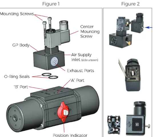
3GP - Spring Return Models Installation Normally Closed Operation. Valve is in closed position when coil is de-ener-gized. Figure 1.
1. If equipped, remove the 1/8” exhaust fi lter from actuator port marked ‘B’.
2. Fit the two o-ring seals into the pockets on the underside of the pilot valve body.
3. Position the pilot valve so that the Exhaust Ports are located on the same side as the Position In-dicator.
4. Insert the mounting screws (M5X32) through the mounting holes in the pilot body valve and tighten until secure.
5. Connect the air supply (50 - 125 P.S.I.) to the 1/8” NPT inlet port and wire for the voltage marked on the coil.
6. GP coil is usually equipped with a ‘DS’ DIN x Strain (Figure 2.) or ‘DC’ DIN x Conduit elec-trical connector. To wire the connector, remove the center mounting screw and, with a small screwdriver, pry the inner element from the body of the connector to expose the termi-nal blocks inside. Route the wire through the hub of the
connector. For the ‘DS’ loosen the sealing nut and ensure the wire insulation passes through the rubber grommet inside the hub. Affi x the wires to the ap-propriate terminal block. Re-tighten sealing nut to secure the wire and provide a seal.
Installation - Normally Open Operation Valve in open posi-tion when coil is de-energized. For Normally Open operation the purchase of a normal-ly open actuator is suggested
i.e. A512NOSR. These models have the internal components assembled so that the actua-tor position indicaactua-tor refl ects the correct position of the valve. Field retrofi t is not suggested and will void warranty.
For those applications where the actuator position indication is not required, remove the red position indicator and install the ball valve in the open position and mount the pilot valve as per Normally Closed Operation.
Pneumatic Actuator Accessory - Solenoid Model GP
Installation
(continued)4GP - Double Acting Models Installation - Normally Closed Operation. Valve in closed po-sition when coil is de-energized. Figure 3.
1. Fit the two o-ring seals into the pockets on the underside of the pilot valve body.
2. Install the orientation screw (M5X10) into the hole on the actuator mounting pad directly beneath the letter ‘A’ ( identifi ed as ‘Normally Closed’ in fi gure 2), leaving 1/16” - 1/8” of the screw protruding above the surface of the mounting face.
3. Position the pilot valve so that actuator orientation screw
fi ts into the shallow drilled hole in the GP body. Nameplate on Pilot Valve Body should face
op-posite Position Indicator.
4. Insert the mounting screws (M5X35) through the mounting holes in the pilot valve body and tighten until secure.
5. Connect the air supply (60 - 125 P.S.I.) to the 1/8” NPT inlet port and wire for the voltage marked on the coil.
6. GP coil is usually equipped with a ‘DS’ DIN x Strain, Figure 4., or ‘DC’ DIN x Conduit elec-trical connector. To wire the connector, remove the center mounting screw, and with a small screwdriver, pry the inner element from the body of the connector to expose the termi-nal blocks inside. Route the wire through the hub of the connector. For the ‘DS’ loosen the sealing nut and ensure the
wire insulation passes through the rubber grommet inside the hub. Affi x the wires to the ap-propriate terminal block. Re-tighten sealing nut to secure the wire and provide a seal.
Installation - Normally Open Operation. Valve in open posi-tion when coil is de-energized. Follow the same instructions for Normally Closed substituting item 2 as follows;
2. Install the orientation screw (M5X10) into the actuator mounting pad directly beneath the letter ‘B’ hole identifi ed as ‘Normally Open’ in fi gure 1. Leave 1/16” - 1/8” of the screw protruding above the surface of the end cap.
Pneumatic Actuator Accessory - Solenoid Model GP
Speci
fi
cations
T
EMPERATURE: -20° F to 350° FAIR SUPPLY: 60 - 125 P.S.I. Suffi cient air delivery must be available at the actuator to ensure depend-able operation. The following precautions should be observed: Air supply should be clean and free of moisture. When dirty or wet air is a problem; a fi lter / separator should be specifi ed; these units are most effective when installed as close as possible to the actuator. A fi lter, when used, should permit a minimum fl ow of 4 scfm at an upstream pressure of 60 P.S.I. Eliminate severe restrictions to air fl ow (certain solenoid valves & fi ttings). The most restricted passage must have an area no smaller than .012 inches square, the area of 1/8” diameter orifi ce. If more than a single actuator is to be supplied by an individual pilot, the minimum passage requirement applies per actuator. All actuator models are permanently lubricated and are not recommended to be used with any other air supply lubricants. TUBING: For short runs up to 5 feet 5/32” I.D. is suitable, 1/4” I.D. will serve up to 30 feet. For longer runs, use 3/8” I.D. or larger.
AIR CONNECTION: Female 1/8” NPT for Model 4GP, 1/4” NPT for Model 3GP
OPERATING COIL: Operating coil technical data is dependent on the specifi c model selected, howev-er, all standard coils as designated by the ‘SC’ code and conform to the following:
Wattage: 5 Watts
Class: F, continuous duty
Protection: IP65 (with connector) dusttight, water resistant, Connection: Mini-DIN Standard MATERIALS:
BODY - PTFE / Anodized Aluminum SPOOL - 18-8 Stainless Steel
SEALS - Nitrile / Viton®
HARDWARE - 18-8 Stainless Steel COIL / BODY - GF Nylon / GF Zytel
Maintenance
Gemini’s model GP Solenoid Valves are engineered to be maintenance free. No adjustments or main-tenance is required to achieve maximum service life. Care must be taken to ensure a clean / dry air supply is provided per the above AIR SUPPLY recommendations.
Pneumatic Actuator Accessory - Limit Switch Model LS-1
Installation
Attachment of Limit Switch NAMUR Mounting Bracket
1. Remove the position indicator from atop the actuator and secure the NAMUR 30 Shaft Cou-pling to the model A500 Actuator Shaft Exten-sion with the #6-32 Set Screw using a medium strength, non-permanent thread locker user supplied.
2. Place the Limit Switch NAMUR Mounting Bracket on top of the actuator.
3. Fasten the Limit Switch NAMUR Mount-ing Bracket to the actuator usMount-ing (2) MountMount-ing Bracket Screws.
4. Slide the position indicator over the NAMUR 30 Shaft Coupling until it ‘snaps’ into place just above the bracket.
Attachment of Limit Switch
1. Fit the bushings, which extend from the Limit Switch housing, into the matching holes in the mounting pad. Push switch housing against pad and verify that switch body touches pad. Secure switch body to pad with two #10-24 set-screws using a medium strength, non-perma-nent thread locker user supplied.
Note: Hex wrench supplied with Gemini Limit Switch Mounting Kits, LSNM-A510-K.
Pneumatic Actuator Accessory - Limit Switch Model LS-1
Wiring
Wiring Specifi cations
Wire Size
#12 AWG Maximum #24 AWG Minimum
Wiring
1. Route the wire to be terminated through the conduit hub and up through the ac-cess space to the terminal block.
2. Strip insulation back 1/4”, insert the stripped ends directly into the proper ter-minal clamps and tighten screws.
3. Internal interconnections between terminal-block and switches, Figure 1. A copy is also inside the Limit Switch Cover. NOTE: If the Switch is installed in a haz-ardous location i.e. where fl ammable vapors or dust are present in the atmo-sphere, replace the cover and tighten securely before connecting the electrical supply circuit. If necessary, a screwdriver shank or similar tool may be engaged in the cover wrenching lugs to assist remov-al and replacement. Terminal Strip Switch Adjustment Screws Figure 1
Speci
fi
cations
MATERIALS:Body / Cover - Aluminum with Tefl on® Impregnated
Hard Anodized (PolyLube®) Surfaces Probes - 316 Stainless Steel
Cover Seal / Probes - Buna N TEMPERATURE: 10° F to 180° F CONDUIT CONNECTION: 1/2” NPT
ELECTRICAL RATING: 10 amp. 250VAC maximum; 1/2 amp. 125VDC; 1/4 amp. 250VDC; 5 amp. 125VAC lamp load. Note: each pole must be the same polar-ity to utilize these ratings.
MICROSWITCHES: Mechanical S.P.D.T. (Single Pole Double Throw)
INTERNAL WIRING CONNECTORS: Screw Clamp NEMA STANDARDS: NEMA 1 (General Purpose); NEMA 4 (Watertight & Dusttight); NEMA 7 (Hazard-ous Locations, Class I Groups B, C, & D); NEMA 9 (Haz-ardous Locations, Class II, Groups E, F, & G); NEMA 12 (Oiltight and Driptight); and NEMA 13 (Oiltight and Dusttight).
UL® LISTINGS: Industrial Control Equipment for use in Hazardous Locations, Class I, Groups B,C, & D and Class II, Groups E, F, & G
Maintenance
Gemini’s model LS-1 Limit Switch is engineered to be maintenance free.
Electric Actuator Models 600
Installation
These instructions detail the procedure for installing a Gemini Model 600 Electric Actuator on a drive-key equipped Gemini Valve Model 76, 86 or 96 Ball Valve.
1. Install locator screws in bottom of the electric ac-tuator and tighten with 4mm hex drive torqued to 30-40 inch lbs. (Figure 1)
2. Place the mounting bracket on actuator so that lo-cator screws fi t into blind holes on bottom of bracket. 3. Check to make sure the bracket is seated fl ush against bottom of electric actuator mounting pad. Install bracket mounting screws with 5mm hex drive torqued to 65-75 inch lbs.
4. Check to make sure that valve is in the closed posi-tion and that the stem nut is in the proper orientaposi-tion with respect to the drive key (Figure 2). Note: Valve will not engage driver unless stem nut is in proper orientation.
5. Verify that the actuator is in the closed position. The override handle should be parallel to the short side of the unit as illustrated.
6. Install the valve into the mounting bracket as shown in Figure 3. Engagement of the valve and drive mechanism should require little effort. The top of the valve should lie fl at in the appropriate step so that the bracket straddles the sides of the hex to re-sist any rotation.
7. Position the retainer on the underside of the valve and fasten to the actuator bracket with the two hex head cap screws. Alternate tightening the screws to ensure balanced tension and to avoid skewing of the valve retainer strap relative to the valve body. A gap should remain between the lower surface of the bracket and the retainer ‘ears’ when the assembly is complete (Figure 4).
Actuator Removal for Ball Valve Installation
In many cases it may be desirable to dismount the actuator from the ball valve for ease of ball valve in-stallation. To do so simply loosen and remove the two Valve Retainer Bolts (Figure 3) and re affi x follow-ing Instruction 7.
Figure 1
Figure 2
Figure 3
Electric Actuator Models 600
Wiring - AC Models
These instructions detail the procedure for wiring Gemini Model 615-120AC.
1. Unlatch and open the override handle to access the handle nut. Remove nut with 3/4” wrench. 2. Remove two (2) socket head screws with 4mm hex wrench. The other (6) screws used to secure the cover are located inside enclosed in a plastic bag. If actuator was previously in service all (8) screws would need to be removed. Remove cover by pulling straight up.
3. Route the wire to be terminated through conduit hub and up through the access space to the terminal block. Strip insulation back 1/4”, insert the stripped ends directly into the proper terminal clamps and tighten screws. All internal connections are labeled in the diagram below.
4. Attach grounding wire to green screw that is located on top of conduction bar. 5. Verify that cover o-ring is properly seated in groove. Replace cover and screws.
120 AC Wiring Schematic
Neutral to Terminal 1 and Hot (+) to Terminal 2 Ball Valve / Actuator will Open. Neutral to Terminal 1 and Hot (+) to Terminal 3 Ball Valve / Actuator will Close. Terminals 4 & 5 can be used for position feedback using motor voltage. NOTES:
AC models require a SPDT (Single Pole Double Throw) switch or device.
Negative (-) to Terminal 1 and Positive (+) to Terminal 2 Ball Valve / Actuator will Open. Positive (+) to Terminal 1 and Negative (-) to Terminal 3 Ball Valve / Actuator will Close. Terminals 4 & 5 can be used for position feedback using motor voltage.
NOTES:
AC models require a SPDT (Single Pole Double Throw) switch or device.
A copy of the above Wiring Schematic can also be found on the inside of the actuator cover. 1. Unlatch and open the override handle to access the handle nut. Remove nut with 3/4” wrench. 2. Remove two (2) socket head screws with 4mm hex wrench. The other (6) screws used to secure the cover are located inside enclosed in a plastic bag. If actuator was previously in service all (8) screws would need to be removed. Remove cover by pulling straight up.
3. Route the wire to be terminated through conduit hub and up through the access space to the terminal block. Strip insulation back 1/4”, insert the stripped ends directly into the proper terminal clamps and tighten screws. All internal connections are labeled in the diagram below.
4. Verify that cover o-ring is properly seated in groove. Replace cover and screws.
Electric Actuator Models 600
Wiring - DC Models
These instructions detail the procedure for wiring Gemini Models 615-12DC and 615-24DC.
Electric Actuator Models 600
Manual Override Handle Operation
Lever Release Buttons
The actuator features a simple push-button oper-ated override with exclusive fold-out lever handle. The push-button manual override system allows the user to easily disengage the electric drive gear train for manual operation of the actuator / ball valve.
All external power must be off prior to using the manual override feature. The actuator manu-al override handle can be used in the closed or open (lever extended) position to provide addi-tional leverage.
To open the handle, pinch the Lever Release But-tons and pull up.
Manual Override Button
Press down the manual override button (atop the center) and turn the handle to manually open or close the actuated valve assembly.
To reengage the drive train, release the override button and turn the handle until the manual override button ‘clicks’ signaling the re-engage-ment of the drive train. The manual override lever handle can then be closed.
Electric Actuator Models 600
Speci
fi
cations
TEMPERATURE: 40° F to 150° F
MOTOR: Reversing, Brushless, Capacitor-Run with Auto-Reset Thermal Overload Protection. GEAR TRAIN: Permanently Lubricated, Maintenance Free
POWER: 120VAC 50/60 Hz Single Phase, 12&24VDC OVERRIDE: Manual - Fold Out Lever Handle
PORTS: (2) 1/2” N.P.T. Conduit CYCLE (INDEX) TIME: 6 Seconds DUTY CYCLE /AMPS:
Model DUTY CYCLE: AMPS: (Full Load)
615-120AC 78% 0.3
615-12VDC 100% 1.0
615-24VDC 100% 0.5
MATERIALS:
Enclosure - Dupont® FR50 Cover, Tefl on® Coated Cast Aluminum Base Shaft - 18-8 Stainless Steel
External Trim - 300 Series Stainless Steel
Maintenance
Gemini’s model 600 Electric Actuators are engineered to be maintenance free. No adjustments or maintenance is required to achieve maximum service life.
All specifi cations herein are subject to change without notice or obligation.
Seller warrants its products for a period of one (1) year, to be manufactured in accordance with our written speci-fi cations and free from material defects in material and/or workmanship. Seller, at its option, will promptly repair or replace any products returned intact to the factory, transportation charges prepaid, which Seller determines to be defective in material and/or workmanship. The foregoing shall constitute the sole remedy for any breach of Seller’s warranty. Care must be taken to assure that the internal media and external environment are com-patible with the materials of the ball valve. For a complete copy of our Warranty please see our Standard Terms and Conditions at www.geminivalve.com
Customer Satisfaction Promise - If for any reason our product(s) or service do not meet / exceed your expec-tations please contact us for prompt support. T 603 244-7931 E [email protected]