C A S E S T U D Y
Open Access
Design of a P-&-O algorithm based MPPT
charge controller for a stand-alone
200W PV system
Salman Salman, Xin AI
*and Zhouyang WU
Abstract
Solar cells convert sun light into electricity, but have the major drawbacks of high initial cost, low photo-conversion efficiency and intermittency. The current-voltage characteristics of the solar cells depend on solar insolation level and temperature, which lead to the variation of the maximum power point (MPP). Herein, to improve photovoltaic (PV) system efficiency, and increase the lifetime of the battery, a microcontroller-based battery charge controller with maximum power point tracker (MPPT) is designed for harvesting the maximum power available from the PV system under given insolation and temperature conditions. Among different MPPT techniques, perturb and observe (P&O) technique gives excellent results and thus is used. This work involves the design of MPPT charge controller using DC/DC buck converter and microcontroller. A prototype MPPT charge controller is tested with a 200 W PV panel and lead acid battery. The results show that the designed MPPT controller improves the efficiency of the PV panel when compared to conventional charge controllers.
Keywords:PV system, Maximum power point tracker (MPPT), Perturb and observe (P&O) technique, Charge controller, Microcontroller
1 Introduction
Solar energy is one of the most important renewable energy resources because it is inexhaustible and eco-friendly, and has been used to provide light, heat and electricity [1, 2]. Solar PV modules have two major problems of low effi-ciency and intermittency, i.e. their effieffi-ciency of converting sun light into electric power is generally less than 17%, and the generated electric power changes with weather condi-tions [3–5]. Moreover, PV cell characteristics (I-V or V-P) are nonlinear and changes with insolation and temperature. In stand-alone solar PV systems, the PV modules and teries are the most expensive components. When the bat-teries are directly connected to the PV modules, there is no protection against overcharging and consequently, battery life-span decreases. To protect batteries from overcharging charge controllers can be used, though conventional charge controllers do not operate PV modules at MPP, resulting in lower efficiency. To improve the efficiency, it is desirable to
operate the PV module at peak power point to deliver max-imum power to the batteries.
MPPT techniques are used to extract the maximum output power from PV modules [6–10], and different DC/ DC converter topologies are used to transfer maximum
power from PV modules to loads/ batteries [11, 12].
Different techniques of MPPT have been proposed, e.g. open circuit voltage methods [13,14], short circuit current methods [15, 16], fuzzy logic technique [17, 18], perturb and observe (P&O) [19–21], incremental conductance (IC) technique [22–24].
In this work, a MPPT charge controller based on the P&O technique is designed, to operate a fixed PV mod-ule at MPP. The hardware implementation of the de-signed 200 W MPPT charge controller is carried out and the prototype is tested for the PV charging system. The results show that such type of MPPT controller im-proves the efficiency of PV panels when compared to conventional charge controllers.
* Correspondence:[email protected]
State Key Laboratory of Alternate Electrical Power System with Renewable Energy Sources, North China Electric Power University, Beijing 102206, China
2 Case description
The renewable energy sources, especially solar cells are attracting the interests of researchers worldwide due to their direct conversion of light into electricity. However, the high-cost, low photo-conversion efficiency and inter-mittency are still need to be addressed. The case study involves the design of MPPT charge controller using DC/ DC buck converter and microcontroller. A prototype MPPT charge controller is tested with a 200W PV panel and lead acid battery. The as-designed MPPT controller improves the efficiency of the PV panel when compared to conventional charge controllers.
3 Discussion and Evaluation
3.1 Photovoltaic system
In PV panels, PV cells convert sunlight into electrical energy, which is one of the best approaches for achieving electrical power for long duration. The conversion from sun light to electrical power greatly depends on various factors such as the insolation level and cell efficiency. Solar PV systems are used today in many applications such as lighting, battery charging, water pumping, and satellite power systems etc. [25].
3.2 PV cell equivalent circuit
An ideal PV cell can be presented by a current source with a diode connected in parallel. In the ideal case, the series and shunt resistances are considered to be zero and infin-ite, respectively. However, in real system, both the series and shunt resistances have finite values and must be con-sidered. In Fig.1, both the ideal and practical equivalent
circuits of a solar cell are shown. From Fig.1bthe gener-ated current (I) by the PV cell is given by
I¼Isc−Id−Ish ð1Þ
I¼Isc− VþIRs
Rsh
−Io e vþIRs nV T−1
ð2Þ
Where VT is the thermal voltage,Rs and Rshrepresent the internal series and parallel resistances, respectively.Isc is the short-circuit current, Io is the reverse saturation current,VDis the voltage across the diode,Iis the current output andnis the ideality factor of the diode (1~ 2).
A simplified model after neglecting the shunt resist-ance is shown in Fig. 1a, and accordingly the following equation can be derived.
I¼Isc−Io e vþIRs
nV T−1
ð3Þ
PV cell output voltage can be found by considering T= KT/qin (3) as
V¼−IRsþAKT
q ln
IscþIo−I
ð Þ
Io ð
4Þ
3.3 PV cell I-V curve
PV cells have nonlinear I-V characteristic, which change with irradiation level and temperature. For standard temperature (25 °C) and irradiation level (1000 W/m2), the I-V curve of a PV cell is shown in Fig. 2, where the maximum power point is always at the knee of the curve as indicated.
Fig. 1Equivalent circuit of Solar cellaideal,bpractical
Fig. 2General I-V curve of PV cell
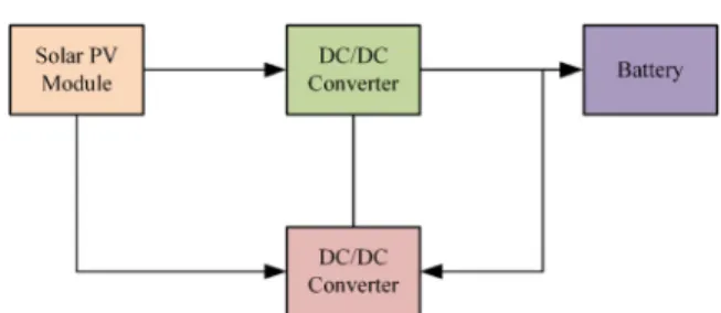
Fig. 3Block diagram of PV system with MPPT charger
3.4 Block diagrams of the proposed system with MPPT charge controller
An off-grid PV system usually consists of PV modules and batteries, which are connected through charge con-trollers. To improve system efficiency, an MPPT charge controller has been introduced as shown in the block
diagram in Fig. 3. The MPPT charge controller is
con-nected between the PV module and battery to extract maximum power from the PV module and deliver to the battery.
3.5 DC/DC converter
DC/DC converters convert one level of DC voltage to another. In the designed project, a buck DC/DC con-verter is used which step down the voltage and step up the current. The basic components used in the converter are a power semiconductor switch (M1), an inductor (L), a diode (D) and a capacitor (C) as shown in Fig.4.
A buck DC/DC converter has two operation modes
associated to switch M1 being closed and opened,
re-spectively. When the switch M1 is closed at time t= 0, the input power is supplied to the load through inductor
L. At that time the diode is reverse biased, and IL
current increases at the rate of:
diL
dt ¼
vL
L ¼
vin−vo
L ;t∈½0;Dt ð5Þ
During this period inductor Lis charging. At timet=
t1, switch M1 opens and the energy stored in the
in-ductor is delivered to the load through diode D which becomes forward biased. The inductor is now dischar-ging andILdecreases at the rate of.
diL
dt ¼
vL
L ¼
−vo
L ;t∈½Dt;T ð6Þ
The diode remains in forward biased until M1 switch is closed. During one switching cycle, the average in-ductor voltage vLis zero under steady state. Since there are two states of vL, both having constant voltage, the average value of the output voltage is given by
vo¼
1
T
Z T
0
voð Þt dt¼
1
T
Z Dt
0
vinð Þt dt¼Dvin ð7Þ
Hence,
vo¼Dvin ð8Þ
Duty cycle (D) is given as:
D¼ ton
tonþtoff ð
9Þ
For continuous conduction mode, the required mini-mum value of inductance can be expressed as:
L¼ voð1−DÞ
2IofPWM
ð10Þ
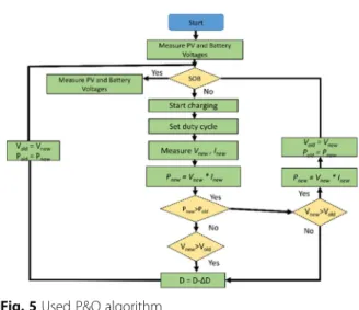
Fig. 5Used P&O algorithm
Fig. 6Picture of the designed MPPT Fig. 7Value of output Voltage and Current on LCD
Table 1Solar panel specification at 1000 W/m2and cell
temperature of 25°
Parameters Specification
Peak Power (Pmax) 200 W
Open circuit voltage/Voc 32.4 V
Max power voltage/Vmp 27 V
Short circuit current/Isc 8A
The capacitor value can be calculated considering the output ripple voltage as
C¼ io
4ΔVfPWM
ð11Þ
Where iois the output current, fPWMis the switching frequency andΔVis the output voltage ripple.
3.6 Maximum power point tracking
To harvest maximum power from the PV panel a charge controller with MPPT capability is proposed in this paper. The two broad categories of MPPT
techniques are the indirect techniques and direct techniques. Indirect techniques include the fixed volt-age, open circuit voltage and short circuit current methods. In this kind of tracking, simple assumption and periodic estimation of the MPPT are made with easy measurements. For example, the fixed voltage technique only adjusts the operating voltage of the
solar PV module at different seasons with the
assumption of higher MPP voltages in winter and lower MPP voltages in summer at the same irradi-ation level. This method is not accurate because of the changing of irradiation and temperature level within the same season.
Another most common indirect MPPT technique is the open circuit voltage (OV) method. In this method, it is assumed that:
VMMP¼kVoc ð12Þ
Where k is a constant and its value for crystalline sili-con is usually to be around 0.7 to 0.8. This technique is simple and is easier to implement compared to other techniques. However the constant k is just an approxi-mation Leading to reduced efficiency, and each time the system needs to find the new open circuit voltage (Vout) when the illumination condition changes. To find the new open circuit voltage, each time the load connected to the PV module must be disconnected causing power loss. Direct MPPT methods measure the current and voltage or power and thus are more accurate and have faster response than the indirect methods. Perturb and observe (P&O) is one of the direct MPPT techniques, which is used here with some modifications.
3.7 Perturb and observe algorithm (P&O)
Typically, P&O method is used for tracking the MPP. In this technique, a minor perturbation is introduced to, cause the power variation of the PV module. The PV output power is periodically measured and compared with the previous power. If the output power increases, the same process is continued otherwise perturbation is reversed. In this algorithm perturbation is provided to the PV module or the array voltage. The PV module voltage is increased or decreased to check whether the power is increased or decreased. When an increase in voltage leads to an increase in power, this means the op-erating point of the PV module is on the left of the MPP [26]. Hence further perturbation is required towards the right to reach MPP. Conversely, if an increase in voltage leads to a decrease in power, this means the operating point of the PV module is on the right of the MPP and hence further perturbation towards the left is required to reach MPP. The flow chart of the adopted P&O algo-rithm for the charge controller is given in Fig.5. When the MPPT charge controller is connected between the
PV module and battery, it measures the PV and battery voltages. After measuring the battery voltage, it deter-mines whether the battery is fully charged or not. If the battery is fully charged (12.6 V at the battery terminal) it stops charging to prevent battery over charging. If the battery is not fully charged, it starts charging by activat-ing the DC/DC converter. The microcontroller will then calculate the existing powerPnewat the output by meas-uring the voltage and current, and compare this calcu-lated power to the previous measured powerPold. IfPnew is greater thanPold, the PWM duty cycle is increased to
extract maximum power from the PV panel. If Pnew is
less than Pold, the duty cycle is reduced to ensure the system to move back to the previous maximum power. This MPPT algorithm is simple, easy to implement, and low cost with high accuracy [26–28].
3.8 MPPT charge controller hardware
The proposed MPPT charge controller is designed using the Altium Designer software, an electronic design automa-tion for printed circuit board (PCB), field -programmable gate array (FPGA) and embedded software design. The pic-ture of the designed hardware shown in Fig.6.
The developed MPPT charge controller is connected between a PV module and battery following the specifi-cations given in Table1. In the first observation, the out-put power of the PV module and the MPPT controller are calculated. The measured output voltage and current of the MPPT controller are shown in Fig.7, and the out-put power for the PV module and the MPPT controller are 86.05 W and 79.69 W, respectively.
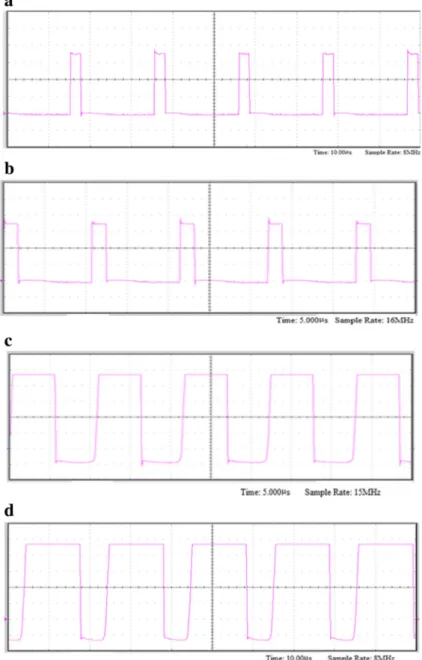
During the tests, the weather was partially cloudy and the output of the PV module varied. The output power of the MPPT controller mainly depends on the PWM duty cycle, which is shown in Fig.8.
Two types of experimental testing were performed. Conventional PWM charge controller was connected to one panel and the MPPT charge controller was con-nected to the other panel with the same specifications. To check the behavior of the controllers at different weather conditions and irradiance levels, three results of input and output power were from 2 pm to 3:30 pm at
Table 2Comparison of PWM and designed MPPT charge controller
Input Reading Output Reading
time Ipv (A) Vpv (V) Ppv (W) Iout (A) Vout (V) Pout (W) Efficiency (%)
PWM charge controller 14:00 7.8 14.4 112.32 5.1 12.6 64.26 57.21%
14:30 6.2 14.1 86.05 4.5 12.5 56.25 65.36%
15:00 4.5 13.9 63.45 3.92 12.7 49.7 78.32%
MPPT charge controller 14:00 7.8 14.4 112.32 6.202 14.1 87.45 77.85%
14:30 6.2 14.1 86.05 5.75 13.86 79.69 92.60%
30 min interval as listed in Table 2. The efficiencies
shown in Table 2 were determined according to the
measured input and output power.
As shown in Table 2, compared to the conventional
charge controller, the developed MPPT charge controller significantly improve efficiency for each of the test time. These results prove that maximum power is harvested from the PV module by using the MPPT charge control-ler. When the battery is fully charged (12.6 V), the MPPT charge controller still provide low current (5 mA) to avoid self-discharge of the battery. Hence, the overall efficiency is improved by using the MPPT charge controller. These results are also depicted in Figs. 9 and 10.
4 Conclusion
To harvest maximum power from a PV module, MPPT based on modified P&O algorithm is implemented in this paper. The hardware consists of a high efficiency DC/DC buck converter and a microcontroller based MPPT controller, and is tested for battery charging. A conventional charge controller and the designed charge controller are compared when charging a 12 V battery from a 200 W solar PV module. It shows that the modi-fied P&O algorithm provides an efficient and reliable maximum power tracking performance under rapid change in irradiance and temperature conditions. The experimental results show that the proposed system is more efficient than the conventional design.
Fig. 10Input and output power when: MPPT charge controller is connected
Abbreviations
MPP:Maximum power point; MPPT: Maximum Power Point Tracker; P&O: Perturb and observe; PCB: Printed circuit board; PV: Photovoltaic; PWM: Pulse width modulation
Funding
2016 national key R & D program of China to support low-carbon Winter Olympics of integrated smart grid demonstration project (2016YFB0900501).
Availability of data and materials
All data is given in the paper or properly cited wherever necessary.
About the Authors
Salman Salman (1987-), male, PHD and Engineer, He received BE degree. From Baluchistan university of engineering and technology in electrical engineering; the MS degree from CIIT Islamabad, Pakistan in 2015. He is currently doing PhD from NCEPU in Major power system.
Xin AI (1964-), male, PHD and Professor, he received the B.S. degree from the Nanjing Institute of Technology, Nanjing, China (now Southeast University); the M.S. degree from the China Electric Power Research Institute, Beijing, China; and the Ph.D. degree from North China Electric Power University (NCEPU), Beijing, in 1985, 1988, and 1999, respectively, all in electrical engineering. He was a Senior Research Scholar with Brunel University, London, U.K., in 2003. He was the Director of the Institute of Power Systems, NCEPU, where he was engaged in research and teaching on power system and automation. He is currently a Professor and a Doctoral Tutor with the School of Electrical and Electronic Engineering, NCEPU. His current research interests include power system analysis and control, and transactive energy. Zhouyang Wu (1994-), male, MS and Engineer, he received B.S. degree from BUAA, now working M.S. degree in electrical engineering at NCEPU in electrical engineering, major in the planning of power system.
Authors’contributions
SS contributed to analysis, modelling and manuscript preparation, Professor AI brought up the original conception and guide the study as a corresponding author, ZW participated in revision and typesetting of the manuscript. All authors read and approved the final manuscript.
Authors’information
Salman Salman is currently pursuing Ph.D. from Department of electrical engineering, North china electric power university, Beijing, China. He received MS degree with Honors in Electrical Power Engineering from Comsats institute of information technology, Islamabad, Pakistan. He received BE degree form Baluchistan University of engineering and technology, khuzdar, Pakistan. His area of interest is power System Protection, Micro grids, DER’s, Renewable Energy Resources, Transactive control and Electrical vehicle-grid integration.
Ai Xin, he received B.S. degree from the Nanjing Institute of Technology, Nanjing, China (now Southeast University); the M.S. degree from the China Electric Power Research Institute, Beijing, China; and the Ph.D. degree from North China Electric Power University (NCEPU), Beijing, in 1985, 1988, and 1999, respectively, all in electrical engineering. He was a Senior Research Scholar with Brunel University, London, U.K., in 2003. He was the Director of the Institute of Power Systems, NCEPU, where he was engaged in research and teaching on power system and automation. He is currently a Professor and a Doctoral Tutor with the School of Electrical and Electronic Engineering, NCEPU. His current research interests include power system analysis and control, and transactive energy.
Zhouyang Wu, he received B.S. degree from BUAA, now working M.S. degree in electrical engineering at NCEPU in electrical engineering, major in the planning of power system.
Competing interests
The authors declare that they have no competing interests.
Received: 1 July 2017 Accepted: 31 July 2018
References
1. Leva, S., & Zaninelli, D. (2006). Technical and financial analysis for hybrid photovoltaic power generation systems. WSEAS Transactions on Power Systems, 5(1), 831–838.
2. Contino, R., Leva, S., & Zaninelli, D. (2007). Integrated renewable sources for supplying remote power systems.WSEAS Transactions on power systems, 2(2), 41–48.
3. Faranda, R., Leva, S., & Maugeri, V. (2008). MPPT techniques for PV systems: Energetic and cost comparison. In Power and Energy Society General Meeting-Conversion and Delivery of Electrical Energy in the 21st Century, 2008 IEEE(pp. 1-6). IEEE.
4. Dubey, S., Sarvaiya, J. N., & Seshadri, B. (2013). Temperature dependent photovoltaic (PV) efficiency and its effect on PV production in the world–a review.Energy Procedia, 33, 311–321.
5. Hamrouni, N., Jraidi, M., & Chérif, A. (2008). Solar radiation and ambient temperature effects on the performances of a PV pumping system.Rev Energ Renouv, 11(1), 95–106.
6. Sivakumar, P., Kader, A. A., Kaliavaradhan, Y., & Arutchelvi, M. (2015). Analysis and enhancement of PV efficiency with incremental conductance MPPT technique under non-linear loading conditions.Renew Energy, 81, 543–550. 7. Ishaque, K., & Salam, Z. (2013). A review of maximum power point tracking
techniques of PV system for uniform insolation and partial shading condition.Renew Sust Energ Rev, 19, 475–488.
8. Bendib, B., Belmili, H., & Krim, F. (2015). A survey of the most used MPPT methods: Conventional and advanced algorithms applied for photovoltaic systems.Renew Sust Energ Rev, 45, 637–648.
9. Ramli, M. Z., & Salam, Z. (2014). A simple energy recovery scheme to harvest the energy from shaded photovoltaic modules during partial shading.IEEE Trans Power Electron, 29(12), 6458–6471.
10. De Brito, M. A. G., Galotto, L., Sampaio, L. P., e Melo, G. D. A., & Canesin, C. A. (2013). Evaluation of the main MPPT techniques for photovoltaic applications.IEEE Trans Ind Electron, 60(3), 1156–1167.
11. Bennett, T., Zilouchian, A., & Messenger, R. (2012). Photovoltaic model and converter topology considerations for MPPT purposes.Sol Energy, 86(7), 2029–2040. 12. Farahat, M. A., Metwally, H. M. B., & Mohamed, A. A. E. (2012). Optimal choice and design of different topologies of DC–DC converter used in PV systems, at different climatic conditions in Egypt.Renew Energy, 43, 393–402. 13. Gokmen, N., Karatepe, E., Ugranli, F., & Silvestre, S. (2013). Voltage band based global MPPT controller for photovoltaic systems.Sol Energy, 98, 322–334. 14. Eltawil, M. A., & Zhao, Z. (2013). MPPT techniques for photovoltaic
applications.Renew Sust Energ Rev, 25, 793–813.
15. Quoc, D. P., Nhat, Q. N., Vu, N. T. D., Bao, A. N., & Lee, H. H. (2011). The new combined maximum power point tracking algorithm using fractional estimation in photovoltaic systems. InPower Electronics and Drive Systems (PEDS), 2011 IEEE Ninth International Conference on(pp. 919-923). IEEE. 16. Noguchi, T., Togashi, S., & Nakamoto, R. (2002). Short-current pulse-based
maximum-power-point tracking method for multiple photovoltaic-and-converter module system.IEEE Trans Ind Electron, 49(1), 217–223.
17. Chekired, F., Larbes, C., Rekioua, D., & Haddad, F. (2011). Implementation of a MPPT fuzzy controller for photovoltaic systems on FPGA circuit. Energy Procedia, 6, 541–549.
18. Radjai, T., Rahmani, L., Mekhilef, S., & Gaubert, J. P. (2014). Implementation of a modified incremental conductance MPPT algorithm with direct control based on a fuzzy duty cycle change estimator using dSPACE.Sol Energy, 110, 325–337. 19. Femia, N., Petrone, G., Spagnuolo, G., & Vitelli, M. (2009). A technique for
improving P&O MPPT performances of double-stage grid-connected photovoltaic systems.IEEE Trans Ind Electron, 56(11), 4473–4482.
20. Patel, H., & Agarwal, V. (2008). Maximum power point tracking scheme for PV systems operating under partially shaded conditions. IEEE Trans Ind Electron, 55(4), 1689–1698.
21. Elgendy, M. A., Zahawi, B., & Atkinson, D. J. (2012). Assessment of perturb and observe MPPT algorithm implementation techniques for PV pumping applications.IEEE transactions on sustainable energy, 3(1), 21–33.
23. Selvan, D. S. (2013). Modeling and simulation of incremental conductance MPPT algorithm for photovoltaic applications. International Journal of Scientific Engineering and Technology, 2(7), 681–685.
24. Ankaiah, B., & Nageswararao, J. (2013). MPPT algorithm for solar photovotaic cell by incremental conductance method. International Journal of Innovations in Engineering and Technology, 2(1), 17–23.
25. Masoum, M. A., Badejani, S. M. M., & Fuchs, E. F. (2004). Microprocessor-controlled new class of optimal battery chargers for photovoltaic applications.IEEE Transactions on energy conversion, 19(3), 599–606. 26. Dabra, V., Paliwal, K. K., Sharma, P., & Kumar, N. (2017). Optimization of
photovoltaic power system: A comparative study.Protection and Control of Modern Power Systems, 2(1), 3.
27. Kumari, J. S., Babu, D. C. S., & Babu, A. K. (2012). Design and analysis of P&O and IP&O MPPT techniques for photovoltaic system.International Journal of Modern Engineering Research, 2(4), 2174–2180.