FPGA IMPLEMENTATION OF ROAD NETWORK EXTRACTION USING
MORPHOLOGICAL OPERATOR
C
HINNATHEVARS
UJATHA,1 ANDD
HARMARS
ELVATHI21ECE Department, SSM Institute of Engineering and Technology, Dindigul, Tamil Nadu, 624002, India; 2ECE
Department, Mepco Schlenk Engineering College, Sivakasi, Tamil Nadu, 626005, India e-mail:[email protected], [email protected]
(Received: February 27, 2016: revised June 3, 2016; accepted June 10, 2016)
ABSTRACT
In the remote sensing analysis, automatic extraction of road network from satellite or aerial images is the most needed approach for efficient road database creation, refinement, and updating. Mathematical morphology is a tool for extracting the features of an image that are useful in the representation and description of region shape. Morphological operator plays a significant role in the extraction of road network from satellite images. Most of the image processing algorithms need to handle large amounts of data, high repeatability, and general software is relatively slow to implement, so the system cannot achieve real-time requirements. In this paper, field programmable gate array (FPGA) architecture designed for automatic extraction of road centerline using morphological operator is proposed. Based on simulation and imple-mentation, results are discussed in terms of register transfer level (RTL) design, FPGA editor and resource estimation. For synthesis and implementation of the above architecture, Spartan 3 XC3S400TQ144-4 device is used. The hardware implementation results are compared with software implementation results. The performance of proposed method is evaluated by comparing the results with ground truth road map as reference data and performance measures such as completeness, correctness and quality are calculated. In the software imple-mentation, the average value of completeness, correctness, and quality of various images are 90%, 96%, and 87% respectively. In the hardware implementation, the average value of completeness, correctness, and quality of various images are 87%, 94%, and 85% respectively. These measures prove that the proposed work yields road network very closer to reference road map.
Keywords: connected component, FPGA, morphological operation, performance measures, road network extraction, satellite image.
INTRODUCTION
Geographic Information Systems (GIS) needs an automatic road extraction process for updating their data (Hu et al., 2007). Manual updating of GIS database is costly, time consuming process and also there is a possibility of error in manual updating of the road network (Jin and Davis, 2005; Huang et al., 2012; Unsalan and Sirmacek, 2012). Therefore, automatic road feature extraction from high resolution satellite image is required to detect the road network in a robust manner. The objective of road feature extraction method is providing a binary mask in which true pixels repre-sent road regions and false pixels indicate non-road regions. Many researchers are developing their own algorithm for automatic road detection and all the work has its own merits and demerits. Mathematical mor-phology is used to process and analyze the images and it plays a vital role in road network extraction. Some of the existing automatic road extraction works based on morpho-logical approach are discussed here.
Miao et al. (2014) proposed a method for road centerline extraction from classified image which consists of the three stages, extraction of feature points using tensor voting, kernel density estimation is used to find probability of each pixel being located on the road centerline and feature points are identified, cen-terline of road is formed by using geodesic method. The performance of this method is proved by com-paring the quantitative measures with other methods.
Shi et al. (2014) presented road extraction method for
para-meters. Automatic road extraction method using road intersection model is presented by Ahmed and Rah-man (2011). The entire process of road intersection detection is divided into two sequential modules. The first module is the detection of road network using different morphological direction filter and the second module is an extraction of road intersection to deter-mine road orientation. Correctness values are measu-red for evaluating this method.
The proposed work of this paper is road network boundary extraction using multi structural element (MSE) based morphological operator and centerline of the network is extracted using morphological ope-rator. In this work, the road network extraction using the morphological operator with MSE and its hardware implementation is proposed. This proposed FPGA architecture is simulated using Verilog and synthesized on Spartan 3 FPGA device.
MATERIAL AND METHODS
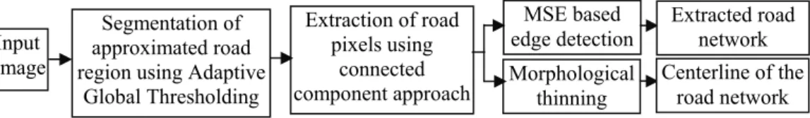
Automatic road network extraction from high re-solution satellite image includes the following stages (Sujatha and Selvathi, 2015). Approximated road region is segmented from satellite image using adaptive global thresholding method, morphological operators are applied to remove unwanted components in that output, extracting road pixels from segmented road region using connected component based trivial opening operations, edge detection using MSE morphological operator is applied to detect the boundary of the road network, and morphological thinning is applied to get centerline of the road network. The detailed metho-dology of proposed work is given in Fig. 1.
Adaptive global thresholding is applied to segment approximated road region from the satellite image. The histogram of the satellite image is analyzed and divided into four main sections to obtain the desired threshold value for segmentation (Singh and Garg, 2013). This approach is used in the case where single value thresholding will not function properly since the threshold value of pixel depends on its position within an image. Therefore, this technique is called as adaptive global thresholding. From this technique,
approximated road regions are identified. The pixels lies in that region are assigned to the value 1 and remaining all the pixels are made to 0. Now the gray image is converted into the binary image. For any pixel in an image, the set of pixels that are connected to that pixel is called connected component of an image (Dalla Mura et al., 2010). The analysis of connected components is mainly used for many auto-mated image processing applications such as road map extraction, line detection, etc. Morphological ope-rators are used to extracting the connected components of an image. Morphological dilation and erosion is the two most important basic morphological operator and other morphology operators are often derived from their combination. These morphological operators are used to extract the connected components of an image (Sujatha and Selvathi, 2015).
Dilation and erosion of a gray scale image G(x, y) by a structural element E(s, t) are denoted as in Eq. 1 and Eq. 2 respectively.
G ْ E(x, y) = max {G(x-s, y-t) + E(s, t)}, (1)
G ٚE(x, y) = min {G(x-s, y-t) - E(s, t)}. (2)
The morphological opening of G and E is defined as erosion followed by dilation and Morphological closing is defined as the dilation followed by erosion. Opening and closing are given in Eq. 3 and Eq. 4 respectively.
G°E = (G ٚE) ْE, (3)
GڄE= (G ْE) ٚE. (4)
Let G is an image and connected components in an image are denoted as G(1), G(2), G(3),…. The first non-zero pixel in an image is p and assigned that value as X0. The connected pixels with this X0 pixel are extracted as per the Eq. 5. That X0 is dilated with structural element E and dilated output is intersected with an image that output is X1. If X1 ≠ X0 then this iteration process is repeated, if X1 = X0 then iteration is stopped and X1 is the first set of the connected component. The above process is continued until all the non-zero pixels are grouped in any one of the connected components.
Fig. 1. Methodology of the proposed work.
Input image
Segmentation of approximated road region using Adaptive
Global Thresholding
Extraction of road pixels using
connected
component approach Morphological thinning MSE based
edge detection Extracted road network Centerline of the
Xk = (Xk-1 ْ E) ∩ G k=1, 2, 3, … (5) Some of these connected components are non-road regions and these unwanted components are removed by using the Trivial opening method. Trivial opening is defined by Serra and Vincent (1992) and it is used to extract the connected components based on some criteria. Let G be an image, {G(n)|n = 1, 2, 3, …,N} is a sequence of connected components in the image G which are extracted using Eq. 5. The trivial opening is defined with a condition T, as follows in Eq. 6.
τo = { G(i),if G(i)satisfy the condition T, ɸ, otherwise} (6)
Therefore, τo is the trivial opening associated with condition T. The trivial opening is used to extract the required portion of an image based on condition T. This operation removes the connected component which is not satisfied the condition T. If connected component satisfied the condition T, then entire region of that components are preserved. So shape and size are not disturbed by this opening. Road areas are easily filtered by trivial opening because roads have appeared as an identical region and long features in satellite images. The roads are extracted by selecting the condition as the long axes of a minimum ellipse for trivial opening operation. The Trivial opening for road detection is expressed as follows in Eq. 7.
Ro = {G| Long axis of axis of minimum ellipse enclosing G(i) >= T}, (7) where G is an image and G(i) is connected compo-nents of an image. Thus, resultant image Ro has the connected components which are greater than T and this resultant image consists of road regions and all unwanted regions are removed.
ROAD BOUNDARY EXTRACTION
USING MSE BASED
MORPHOLOGICAL EDGE
DETECTION
The resultant image of the trivial opening method consists of road network regions. The boundary of this network is extracted using MSE based morpho-logical edge detection. Edges of an image are detected using morphological gradient edge detector and it is denoted by Eg(G). The edge is detected by using the Eq. 8.
Eg (G) = (GלE) ْE-(GڄE) ٚ E, (8) where G is an image and E is a structural element.
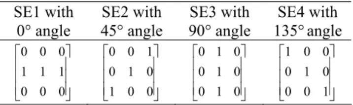
The performance of the morphological based edge detection mainly depends on the choice of structural element (SE). The shape and size of SE affect the edge detection result. Single SE is only sensitive to image edge which has the specific direction (Dalla Mura et al., 2010). Thus, the MSE based edge detection algorithm is developed, that is detecting the image edges with different directions, and each SE detects an image edge in the corresponding direction. The larger SE detects the thicker edge than smaller SE based edge detection method. Thus, the size of SE is 3*3 and the direction angles of SE are 0°, 45°, 90°and 135° are chosen. These SEs are shown in Fig. 2.
SE1 with 0° angle SE2 with 45° angle SE3 with 90° angle SE4 with 135°angle ⎥ ⎥ ⎥ ⎦ ⎤ ⎢ ⎢ ⎢ ⎣ ⎡ 0 0 0 1 1 1 0 0 0 ⎥ ⎥ ⎥ ⎦ ⎤ ⎢ ⎢ ⎢ ⎣ ⎡ 0 0 1 0 1 0 1 0 0 ⎥ ⎥ ⎥ ⎦ ⎤ ⎢ ⎢ ⎢ ⎣ ⎡ 0 1 0 0 1 0 0 1 0 ⎥ ⎥ ⎥ ⎦ ⎤ ⎢ ⎢ ⎢ ⎣ ⎡ 1 0 0 0 1 0 0 0 1
Fig. 2. Multistructural elements used in this method
These structure elements comprise almost all the directions of lines extend in the image. By using these four SEs, horizontal, vertical and diagonal edges are extracted. Morphological gradient edge detection in 0o is detected using the Eq. 9.
E1 (G) = (GלSE1) ْSE1-(GڄSE1) ٚSE1. (9) Morphological gradient edge detection in 45° is detected using the Eq. 10.
E2 (G) = (GלSE2) ْSE2-(GڄSE2) ٚSE2. (10) Morphological gradient edge detection in 90o is detected using the Eq. 11.
E3 (G) = (GלSE3) ْSE3-(GڄSE3) ٚSE3. (11) Morphological gradient edge detection in 135o is detected using the Eq. 12.
E4 (G) = (GלSE4) ْSE4-(GڄSE4) ٚSE4, (12)
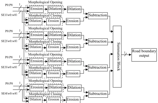
where G is a gray scale image, SE1, SE2, SE3, SE4 are structural elements and values are given in Fig. 2. Image fusion method is used to get the final edge map of an image as given Eq. 13.
Em (G) = ∑ Ei (G)/M, (13)
Fig. 3. Block diagram for boundary of road network
EXTRACTION OF CENTERLINE
OF ROAD NETWORK
The resultant image of trivial opening have the regions of the entire road network and by using MSE based edge detection method boundary of the road net-work is obtained. The morphological thinning operation is applied to get the centerline of the road network. The thinning of an image G by a structural element E is defined as in Eq. 14.
G ٔE = G - (G*E) = G ځ (G*E)C, (14) where (G*E) represent the hit-or-miss transform used to identify specified configuration of pixels (Reddy et al., 2012) and it is given in Eq. 15.
G*E = (G ٚE1) ځ (GC ٚ E2), (15) where E1, E2 are subsets of E related with object and background respectively.
FPGA IMPLEMENTATION OF
ROAD NETWORK EXTRACTION
The FPGA architecture is proposed for road center-line extraction using morphological operator. For real time application, hardware implementation is most needed. The overall flow diagram for FPGA imple-mentation of road network extraction is shown in Fig. 4. The Matlab program is used to convert image data into hexa data file. FPGA architecture designed to process these data and produces the output which is converted into image format by using Matlab program.
FPGA ARCHITECTURE FOR
ROAD EXTRACTION
The block diagram of proposed FPGA architecture is shown in Fig. 5. It consists of adaptive threshold module, connected component labelling, trivial opening, Morphological edge detection, and morphological thinning.
Fig. 4. Flow Diagram for FPGA implementation of road network extraction.
Input Image
Matlab Program (Image to hexa file
converter)
FPGA Architecture for road network
extraction
Extracted road network
output Matlab Program
(Hexa file to image converter) Morphological Closing
SE1[w0:w8]
1 Erosion Dilation P0:P8 1 Morphological Opening
Dilation
Subtraction Erosion
Erosion Dilation
Morphological Closing SE2[w0:w8]
1 Erosion Dilation P0:P8 1 Morphological Opening
Dilation
Subtraction Erosion
Erosion Dilation
Morphological Closing SE3[w0:w8]
1 Erosion Dilation P0:P8 1 Morphological Opening
Dilation
Subtraction Erosion
Erosion Dilation
Morphological Closing SE4[w0:w8]
1 Erosion Dilation P0:P8 1 Morphological Opening
Dilation
Subtraction Erosion
Erosion Dilation
1
Su
mmatio
n Blo
ck
Fig. 5. Block diagram for road extraction module.
The input image is converted into binary using adaptive threshold method. The architecture is shown in Fig. 6. In this architecture, P is the 8-bit pixel value of an image and T is the 8-bit threshold value which is found using adaptive threshold method. If pixel value P is greater than threshold value T, then the output is 1 or output is 0. Thus, 8-bit input pixel is converted into binary format. This threshold output contains some unwanted region. The unwanted region is removed using connected component extraction. Connected components are extracted using the iterative Eq. 7. The algorithm behind the extraction of the connected component is as follows. Converted binary image from the adaptive threshold method is assigned as matrix A, any one of SE from Fig. 2. is chosen and
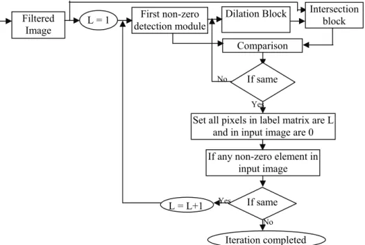
assigned as B. The first non-zero element position in the input matrix A is found. The matrix X is initia-lized with zeros and place 1 in the non-zero element position found in the previous step. Morphological dilation using the structural element B on matrix X is performed. The dilated matrix is intersected with the matrix A. Check whether Y==X. If both are not equal, then perform dilation and intersection again. If both are same, then iteration is stopped. The non-zero ele-ments position in the Y is labelled with number L. where L is the number of connected component in that image A. Similarly, place zero in those positions in the input matrix A. The block diagram for connected component labelling is shown in Fig. 7.
Fig. 6. Block diagram for adaptive threshold module.
Input image
Adaptive threshold module
Connected component
labelling Morphological thinning
Extracted Road network boundary Centerline of the
road network MSE based
edge detection Trivial
opening
1
1 1 T[7]
P[7]
T[6] P[6]
T[5] P[5]
T[4] P[4]
T[3] P[3]
T[2] P[2]
T[1] P[1]
T[0] P[0]
B 1
0 1
1
1 1
1 1
1 1
1 1
1 1
1 1
Fig. 7. Block diagram for connected component labelling.
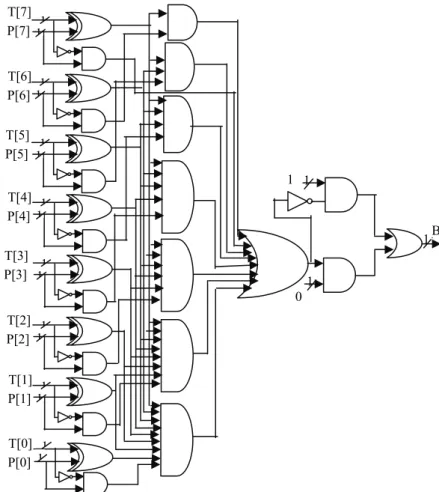
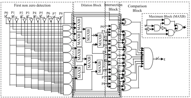
The connected component block diagram consists of nonzero detection, dilation, and intersection modules. The architecture of these modules is given in Fig. 8. The first non-zero detection block is used to find the first non-zero values in the given matrix and it has nine input and nine output. Table 1 shows the con-ditions to find the first zero among nine neighborhood pixels. The internal architecture for this block is shown in Fig. 8.
The first non-zero block is followed by dilation block which is used to find the maximum among the neighbors. That morphological dilation architecture and an internal circuit of the maximum block (MAXB) used in dilation is also given in Fig. 9. The dilated output is followed by intersection block. Two binary
number is intersected by using the AND operations. The comparison block is used to compare the output of intersection block with non-zero block output. If both outputs are same, iteration is stopped otherwise the entire process is repeated as shown in the Fig. 7. By using these processes connected component is identified and the unwanted component is removed by using the trivial opening method. In the trivial opening method, the length of each connected component is measured and long length component is retained re-maining are removed. These processes give the road region in an image. Road boundary is extracted from the processed road region image using MSE based morphological edge detection method. The architecture of road boundary detection using MSE based morpho-logical operator is shown in Fig. 9.
Table 1. Conditions to find first nonzero pixels.
Input A Output A Output
P0 P1 P2 P3 P4 P5 P6 P7 P8 N0 N1 N2 N3 N4 N5 N6 N7 N8 Expression
1 x x x x x x x x 1 0 0 0 0 0 0 0 0 N0 = P0
0 1 x x x x x x x 0 1 0 0 0 0 0 0 0 N1 = P1’.P0
0 0 1 x x x x x x 0 0 1 0 0 0 0 0 0 N2 = P2’P1.P0
0 0 0 1 x x x x x 0 0 0 1 0 0 0 0 0 N3 = P3’P2.P1.P0
0 0 0 0 1 x x x x 0 0 0 0 1 0 0 0 0 N4 = P4’P3.P2.P1.P0
0 0 0 0 0 1 x x x 0 0 0 0 0 1 0 0 0 N5 = P5’P4.P3.P2.P1.P0 0 0 0 0 0 0 1 x x 0 0 0 0 0 0 1 0 0 N6 = P6’P5.P4.P3.P2.P1.P0 0 0 0 0 0 0 0 1 0 0 0 0 0 0 0 0 1 0 N7 = P7’.P6.P5.P4.P3.P2.P1.P0 0 0 0 0 0 0 0 0 1 0 0 0 0 0 0 0 0 1 N8 = P8’.P7.P6.P5.P4.P3.P2.P1.P0
Iteration completed L = L+1
If any non-zero element in input image
If same Filtered
Image
First non-zero detection module
Comparison
Dilation Block Intersection block
Set all pixels in label matrix are L and in input image are 0 L = 1
If same Yes No
Yes
MA
XB
P4
Intersection Block First non zero detection
bl k
Dilation Block Comparison Block 1 P7 1 1 1 P8 P6 P5 P3 P2 P1 1 1 1 1 1 1 1
P0 P1 P2 P3 P4 P5 P6 P7
1 P8 M AXB MAX B MAXB
MAXB MAXB
MAX
B
P0
MAXB
E
Maximum Block (MAXB)
1 1
1
Fig. 8. International architecture for connected component labelling.
Minimum Block (MINB)
1 1
1
1
Boundary of road network 1
1 1 MINB
MAXB MAXB MAXB MINB P3 1 P4 1 P5 1 MAXB 1 1 1 MAXB
MINB MINB MINB MAXB P3 1 P4 1 P5 1 MINB 1 1 1 MINB MAXB MAXB MAXB MINB P2 1 P4 1 P6 1 MAXB 1 1 1 MAXB MINB MINB MINB MAXB P2 1 P4 1 P6 1 MINB 1 1 1 MINB MAXB MAXB MAXB MINB P1 1 1P4
P7 1 MAXB 1 1 1 MAXB MINB MINB MINB MAXB P1 1 P4 1 P7 1 MINB 1 1 1 MINB MAXB MAXB MAXB MINB P0 1 P4 1 P8 1 MAXB 1 1 1 MAXB
MINB
MINB
MINB MAXB P0 1 1 P4
P8
1
MINB
Subtraction Block
Fig. 9. Architecture diagram of morphological based road boundary detector.
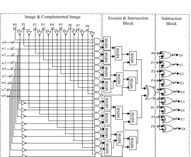
The architecture consists of the maximum block (MAXB), minimum block (MINB), subtraction block and finally adds the four outputs to get the road pixels. The architecture provides the boundary of the road network. The centerline of that network is extracted using morphological thinning operations. The thinning of an image G by SE is defined in terms of the hit-or-miss transform. The block diagram for morphological
thinning is shown in Fig. 10 and internal architecture for thinning is shown in Fig. 11.
Image
Image
Morphological Erosion Complemented
Image
Intersection Hit or Miss Transform
Morphological Erosion
Subtraction
Fig. 10. Block diagram of morphological thinning.
1 1 1 1 1
1
1 1
1
1 P4 1
MINB
MINB
MINB
MINB
MINB
MINB
MINB
MINB
MINB
MINB
MINB
MINB
MINB
MINB
MINB
MINB P0 1
P1 1
P2 1
P3 1
P5
P6 1
P7 1
P8 1
E4 E3 E2 E1 E0
E5
E6
E7
E8 1
1 1
1 1
1 1 1 1
1
Image & Complemented Image
1 1 1 1 1 1
P0 P1 P2 P3 P4 P5 P6 P7
1 1P8
w0 w1
w2
w3 w4
w5
w6
w7 w8
Erosion & Intersection
Block Subtraction Block
Fig. 11. Internal architecture of morphological thinning.
RESULTS
The proposed architecture is implemented on a Xilinx Spartan 3 FPGA device. The sub-modules of the system are individually coded in Verilog and simu-lated using Xilinx ISE simulator.
The synthesis and implementation in device Spar-tan3 XC3S400TQ144 help to determine the resource utilization which indicates the amount of resources
exploited by the entire architecture. Table 2 shows the number of Flip-Flops, LUT, Slice, I/Os utilized and timing summary.
Table 2. FPGA resource utilization and timing sum-mary of proposed architecture.
Resources Count Number of Slices 810/3584 (22%)
Number of Slice Flip-Flops 1012/7168 (14%) Number of 4 input LUTs 897/7168 (12%)
Number of IOBs 22/97 (20%)
Number of GCLKs 1/8 (12%)
Minimum period 8.835ns
Maximum Frequency 113.186MHz
Minimum input arrival time
before clock 10.364ns
Maximum output required time
after clock 7.430 ns
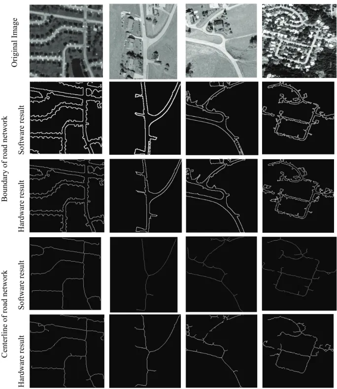
Total memory usages 195912 kilobytes The designed FPGA architectures for road boundary network extraction and road centerline extraction are tested on satellite images and obtained hardware results are compared with software implementation results which are given in Fig. 12.
This comparison proves that hardware implemen-tation result is merely equal to software result.
PERFORMANCE EVALUATION
OF ROAD EXTRACTION
The performance of the road network detection is also analyzed quantitatively using various measures. Performance measures such as completeness, correct-ness, and quality are the most important parameters for the evaluation of the road extraction. To measure
these parameters, extracted road network is compared with manually drawn ground truth road map (Heipke
et al., 1997). Digitized manually drawn road map is
obtained using the software GIMP (GNU Image Manipulation Program). GIMP is high quality freely available software for image processing applications (Solomon, 2009). The matched extracted road data are calculated as True Positive (TP) and the unmatched extracted data is calculated as False Positive (FP).The unmatched reference data are calculated as False Negative (FN). The completeness is the ratio between matched reference road data with the total length of reference road map. The completeness is calculated by using the Eq. 16.
Comp % = TP/(TP+FN)*100. (16) The correctness represents the percentage of cor-rectly extracted road data and it is measured by using the following Eq. 17.
Corr % = TP/ (TP+FP)*100. (17) The goodness of the road extraction result is mea-sured using the quality measures. The value of quality is calculated by using the following Eq. 18.
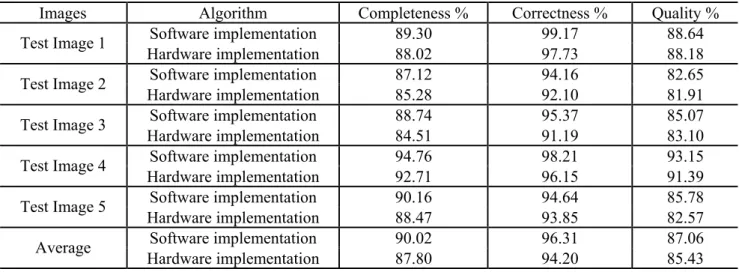
Qual % = TP/ (TP+FP+FN)*100 (18) The performance measures such as Completeness, Correctness, and Quality are evaluated for proposed work on various test images. These measures are calculated for hardware implementation results and tabulated in Table 3.
This comparison Table proves that hardware imple-mentation result is almost equal to software result.
Table 3. Performance measures comparison of hardware and software implementation result of the proposed method.
Images Algorithm Completeness % Correctness % Quality %
Software implementation 89.30 99.17 88.64
Test Image 1
Hardware implementation 88.02 97.73 88.18
Software implementation 87.12 94.16 82.65
Test Image 2
Hardware implementation 85.28 92.10 81.91
Software implementation 88.74 95.37 85.07
Test Image 3
Hardware implementation 84.51 91.19 83.10
Software implementation 94.76 98.21 93.15
Test Image 4
Hardware implementation 92.71 96.15 91.39
Software implementation 90.16 94.64 85.78
Test Image 5
Hardware implementation 88.47 93.85 82.57
Software implementation 90.02 96.31 87.06
Average
Original Image
Software resu
lt
Boundary of
road network
Hardwar
e res
ult
Software resu
lt
Centerline of road network
Hardwar
e res
ult
Fig. 12. Comparison of hardware implementation results with software implementation.
DISCUSSION
Road centerline extraction of high resolution satel-lite images using morphological operation is proposed in this work. The proposed work includes the following steps such as segmentation of approximated road regions using adaptive global threshold method; trivial opening with the criteria of a long axis of the
device. The device utilization is very less and time delay is 8.835ns (3.678ns logic, 5.157ns route). The total memory required for implementation of the deve-loped method has been found as 195912 kilobytes. This architecture uses only 14% slice FFs on Xilinx Spartan 3 XC3S400-4TQ144. The proposed method is implemented on various satellite images and results in both software and hardware implementation are given. The completeness, correctness, and quality measures are evaluated for both hardware and software imple-mentation and results are compared. These comparisons proved that hardware result is close to software result.
REFERENCES
Ahmed B, Rahman MF (2011). Automatic road extractions from high resolution satellite imagery using road intersection model in urban areas. Comput Eng Intell Syst 2:82–93.
Dalla Mura M, Benediktsson JA, Waske B, Bruzzone L (2010). Morphological attribute profiles for the analysis of very high resolution images. IEEE T Geosci Remote 48:3747–62.
Heipke C, Mayer H, Wiedemann C, Jamet O (1997). Eva-luation of automatic road extraction. Int Arch Photo-gram Remote Sens 32:151–60.
Hu J, Razdan A, Femiani JC, Cui M, Wonka P (2007). Road network extraction and intersection detection from aerial images by tracking road footprints. IEEE T Geosci Remote 45:4144–57.
Huang Z, Zhang J, Wang L, Xu F (2012). A feature fusion method for road line extraction from remote sensing image. Proc IEEE International Symposium on Geo-
science and Remote Sensing, 2012 July 22;52–5. Jin X, Davis CH (2005). An integrated system for
automa-tic road mapping from high-resolution multi-spectral satellite imagery by information fusion. Inform Fusion 6:257–73.
Miao Z, Wang B, Shi W, Wu H (2014). A method for accurate road centerline extraction from a classified image. IEEE J Appl Earth Obs Remote Sens 7:4762–71. Reddy GVR, Vijaya Kumar V, Reddy MA (2012). Morpho-logical texture synthesis algorithm using pixel and patch based approach. Int J Sci Eng Res 3:1–4.
Serra J, Vincent L (1992) An overview of morphological filtering. Circ Syst Signal Proc 11:47–108.
Shi W, Miao Z, Wang Q, Zhang H (2014). Spectral–spatial classification and shape features for urban road center-line extraction. IEEE Geosci Remote Lett 11:788–92. Singh PP, Garg RD (2013). Automatic road extraction from
high resolution satellite image using adaptive global thresholding and morphological operations. J Indian Soc Remote Sens 41:631–40.
Solomon RW (2009). Free and open source software for the manipulation of digital images. Am J Roentgenol 192:330–4.
Sujatha C, Selvathi D (2015). Connected component-based technique for automatic extraction of road centerline in high resolution satellite images. EURASIP J Image Video Proc 8:1–16.