Accredited by RISTEKDIKTI, Decree No: 32a/E/KPT/2017 doi: 10.14203/jet.v18.75-80
Rotational Speed Control of Brushless DC Motor
Using Genetic Algorithm Optimized PD Controller
Rizqi Andry Ardiansyah *, Edwar Yazid
Research Center for Electrical Power and Mechatronics Indonesian Institute of Sciences
Jl.Cisitu Sangkuriang 154d/21, 40135 Bandung, Indonesia
Abstract
Controlling the rotational speed of brushless DC (BLDC) motor is an essential task to improve the transient and the steady state performances under loaded condition. Rotational speed control of BLDC motor using genetic algorithm optimized proportional-derivative (PD) controller to form what the so-called the genetic algorithm-PD (GA-PD) controller is proposed in this paper. Control system is realized in a microcontroller namely a 16MHz Atmega 2560 with an absolute encoder as a position sensor. The effectiveness of the GA-PD controller is tested under constant and varying step functions with the Ziegler-Nichols-PD (ZN-Ziegler-Nichols-PD) controller as a benchmark. Experimental results show that the GA-Ziegler-Nichols-PD controller has slower speed than the ZN-Ziegler-Nichols-PD controller, but the latter has overshoot and small oscillations during its steady state condition as a consequent of having a fast rise time.
Keywords: Rotational speed, BLDC motor, PD controller, genetic algorithm
I. INTRODUCTION
Brushless DC motor (BLDC) has been widely used for many years in many industrial application because of its efficiency and reliability. There has been a massive research interest in the area of modelling and control of BLDC as reported in the literatures. Recent research, for instance, an efficient ANFIS based speed controller for BLDC motor is proposed as in [1]. ANFIS controller is modelled through modified data of the fuzzy tuned PID controller and is simulated under varying speed and load conditions. Control system responses shows that the proposed controller is superior to the classical PI and fuzzy tuned PID controller and fuzzy variable structure controller. Bat algorithm optimized online ANFIS for the same plant is also proposed [2]. Their results show that the proposed controller eliminates the uncertainty problem due to load disturbance and enhance the time domain specifications and performances in all operating conditions. The same algorithm is then enhanced using the same system by proposing a fuzzy online gain tuned windup PID and fuzzy PID supervised ANFIS [3]. The results show that the windup problem can be eliminated and also improve control system performances.
Performance of self-tuning fuzzy PID controller and model reference adaptive control (MRAC) with PID compensator is compared by [4]. The result shows that combination of MRAC with PID control compensator eliminates the overshoots and steady-state error. Comparison between antiwindup PI controller and conventional PI controller in brushless DC motor speed
controlling is conducted by [5]. Simulation and experimental results show that the anti-windup PI controller has better anti disturbance ability, less overshoot, and less settling time. Other controller variants such as hybrid fuzzy-PID, PSO-PID and BF-PID can be found in references [6]-[10], respectively.
Contribution of this paper is put on the experimental control of BLDC motor by using proportional-derivative (PD) controller which is optimized by genetic algorithm (GA). The experiment is conducted in purpose to optimize the gains of PD controller which is an essential task in controlling the BLDC motor. Control algorithm is realized in a plant that consists of a BLDC as a controlled system, an encoder sensor for position sensor, and an Arduino Atmega 2560 board.
The reminder of this paper is organized as follows: Section 2 describes about the modelling of BLDC motor, followed by the concept of PID controller in Section 3. Model of Genetic Algorithm combined with PD controller is put on Section 4. Section 5 describes the experimental setup and Section 6 presents the experimental results and discussions. Finally, some conclusions are written in Section 7.
II. MODEL OF BLDCMOTOR
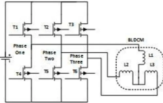
In this study, KC AXHM5100 Vexta Brushless DC Motor is used. KC AXHM5100 Vexta BLDCM is a brushless dc motor produced by Oriental Motor Corp. This type of motor has a three-phase brushless dc that has schematic diagram can be shown below in Figure 1.
The mathematical model of three-phase BLDC motor with several assumptions has been outlined in [10], but it is revisited here for a concise notation. General voltage equation for the underlying system can be written in a state-space as expressed in (1).
* Corresponding Author. Email: [email protected]
Received: June 29, 2018 ; Revised: December 12, 2018 Accepted: December 19, 2018 ; Published: December 31, 2018
Figure 1. Schematic diagram of three-phase BLDC motor. z y x z y x z y x z y x e e e i i i L L M M L M M M L i i i R R R u u u 0 0 0 0 0 0 (1)
Terms in (1) can be explained as follows: ux, uy, uz are
phase coils voltage (V), ix, iy, iz are three-phase current
from coils stator voltage (A), ex, ey, ez are back EMF (V)
and R is phase resistant (Ω) while L is phase inductance M (H). The three-phase current at balanced condition is formulated in (2), while the electromagnetic torque is given in (3).
0
y zx
i
i
i
(2) m z z y y x x ei
e
i
e
i
e
T
(3)ωm denotes the mechanical angular speed, which is the
variable control. This speed is an essential component in the mechanical torque as shown in (4). By relating the electromagnetic torque in (3) and mechanical torque in (4), the rate of mechanical angular speed is calculated using (5). m m m B dt d J
T
(4)m m e m J B J T T dt
d
(5)
Where
J
andB
in Equation 5 are moment inertia and friction coefficient, respectively. By using technical specifications shown in Table 1 [11] and respective chosen parameters, control simulation of BLDC motor can be performed and compared to the experiment in the next section.TABEL 1
KC AXHM5100 BLDC MOTOR SPECIFICATION Rated Output Power - HP(W) 1/8(100) Voltage - VDC 24 +/- 10% Rated Input Current - A 6 Rated Torque (N·m) 0.40 Permissible Load Inertia J (10-4 kg·m2) 5.6
Speed max (RPM) 3000
III. PID AND GA-PDCONTROLLER
A. PID Controller
PID controller is one of the classical closed-loop control systems that has been widely used in many industrial applications for many years due to its simplicity and robustness in the engineering systems. The main principle of PID controller is about to constitute a control action with proportional, integral, and differential gains then choosing the best combination and its corresponding optimal gains in order to control the plant. The control diagram block in discrete time index is shown in Figure 2.
Error of the plant, which is denoted by e(n), can be obtained by differentiating the reference input value
yi(n) and output value yo(n) as expressed in (6). Error and its derivative are then multiplied with the proportional gain (Kp), integral gain (Ki) and derivative
gain (Kd) to form the control action (Un) which is sent
to the plant. Complete expression of control action can be written as shown in (7).
n
y
n
y
n
e
i
o (6)
n K e(n) K e(n) K e (n)u p i
d T (7)Under any types of system input, the gains in (7) significantly affect the closed-loop system in Figure 2. Suboptimal gains lead to the system becomes unstable, high overshoot and large steady-state error. The gains must be designed to match the system input (set-point) and the system output by giving the corrective action in terms of control action. Hence, the GA algorithm is employed to optimize those gains.
B. GA-PD Controller
Optimization process of the gains of PD controller,
Kp and Kd through GA algorithm is depicted in Figure 3.
Initial gains, { Kp, Kd} are created randomly and are
called as chromosomes to form one population. Each chromosome in the population is evaluated using following cost function as formulated in (8).
N nd
n
n
SSE
1
(8)Figure 2. PID control diagram block.
Kp
Kd
Elitism CrossOver
Cost Function, Eq. (8)
Selection Mutation
e Chromosomes
Gains
New Chromosomes Δe
Figure 3. Gains optimization process in GA-PD controller.
PDC BLDC
Motor
+ +
ωd (n) e(n)
Δe(n)
GA
ω(n) u(n)
Figure 4. Diagram block of GA-PD controller.
IV. EXPERIMENTAL SETUP
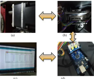
Experiment is conducted in mechatronic division laboratory, Research Centre for Electrical Power and Mechatronics, Indonesian Institute of Science, where the experimental setup for implementing the proposed GA-PD controller is shown in Figure 5. There are two main electronic circuits used in this experiment, a 16MHz Atmega 2560 microcontroller unit and a BLDC motor driver unit, while a 3 phases 24Volt/100 watt AXH Series BLDC motor from Oriental motor as a plant.
(a) (b)
(c) (d)
Figure 5. Experimental setup (a) BLDC motor (b) BLDC driver circuit (c) computer (d) microcontroller.
The 16MHz Atmega 2560 microcontroller unit as a main controller is used to drive the BLDC motor as well as to record the motor speed. The maximum voltage is 24 Volt, and is limited up to 5 Vref Pulse Width Modulation Signal. The internal 30 pulses per revolution rotary encoder sensor is used to measure the motor speed. Before conducting the experiment, the connection of BLDC motor its driver unit must be ensured. Five wire signal pins (Start/Stop, Run/Brake, CW/CCW, EXT Inp, Speed Output) from BLDC motor driver unit is then connected to five pins of microcontroller. External interrupt and timer feature in Atmega 2560 are used to measure the motor speed. In order to record the motor in a database in a computer, a serial communication is used to send the speed data from microcontroller to computer. The sampling rate for the experiment is 50 milliseconds.
V. RESULTS AND DISCUSSION
In this section, performance of the proposed GA-PD controller is investigated under two step functions, constant and varying step functions. Other functions such as sinusoidal function are not elaborated in this study. Parameters used in the GA-PD controller are given by 50 individuals in population size of 0.4 for hyper-mutation rate with a crossover rate of 0.65. GA-PD controller is executed in 50 iterations with the interval for the searching space is 0 ≤ x ≤ 50 for { Kp, Kd}.
Control performances in time domain are assessed in terms of rise time, settling time, overshoot and peak time and compared. BLDC motor is commanded to track a rotational speed ωd → 30 rps by giving a
constant step function. The control response for time duration of 5 second is shown in Figure 6(a). The figure depicts that the BLDC motor is able to track the commanded speed and all controllers have successfully reached it with respect to time. However, each controller has different performances during the tracking especially for the GA-PD controller. The controller tracks the commanded speed slower than the ZN-PD controller. However, the ZN-PD controller has small oscillations during its steady state condition. This is a consequent of having high gains ZN-PD controller as shown by Table 3.
Hence, it leads to a fast rise time as confirmed by Table 3 and high control action as shown in Figure 6(b). Table 3 also shows that the fast rise time of ZN-PD controller results in overshoot of 6.67%. However, settling time for both controllers is almost similar in this case. Details of performances and the gains of each controller are tabulated in Table 3 and Table 4, respectively.
TABEL 2 PARAMETER OF GA GA
Number of iterations 50 Selection Roulette Wheel Number of population 50 Crossover rate 0.65
Number of optimized
(a)
(b)
Figure 6. Constant step function, (a) control response (b) control action.
TABEL 3
CONTROLLER’S PERFORMANCES UNDER CONSTANT STEP FUNCTION
Performance ZN-PD GA-PD
Rise time (s) 0.17 0.23
Settling time (s) 4.67 4.62
Overshoot (%) 6.67 0
Peak time (s) 3.85 2.5 TABEL 4
GAIN OF CONTROLLERS FOR CONSTANT STEP FUNCTION
Controller Gain
P D
ZN-PD 1.58 0.4
GA-PD 0.85 0.02
In optimizing the gains, PD controller optimized by GA algorithm produces a cost function as shown in Figure 7. It displays the cost function with respect to the number of iterations. As observed, the cost exhibits a gradual convergence and seems like a ladder function as the number of iteration increases. However, the cost function starts to converge after the-9th iteration and is steady to a certain value. Further, BLDC motor is commanded to track a rotational speed ωd → 10, 20, 50,
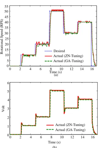
40, 30 rps by giving a varying step function. Varying step function represents the varying load condition. The results are shown in Figure 8. Again, the
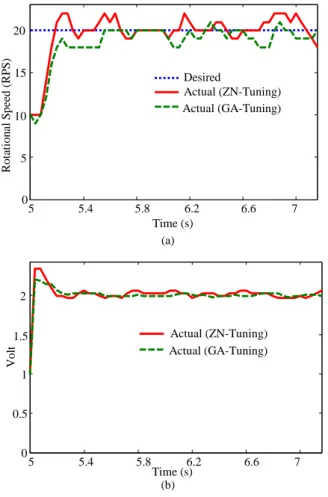
BLDC motor is able to track the commanded speed and both controllers have successfully tracked it with respect to time. For clarity, control response and action are zoomed at time window of 5-7 s, and shown in Figure 9. Finding results in the constant step function seem similar for this case.
In the time duration, ZN-PD controller has faster rise time than GA-PD controller, where it is 0.08 s against 0.175 s. However, it generates overshoot of 22.22 %. In this case, GA-PD controller again shows it superior against the ZN-PD controller in term of minimum overshoot. This is confirmed by Figure 8 and Table 5. Similar with constant step function, gains resulted from GA-PD controller are lower than ZN-PD controller as shown by Table 6. It contributes to the fast rise time and high control action of ZN-PD controller as
Figure 7. Cost function for constant step function.
(a)
(b)
Figure 8. Varying step function (a) control response (b) control action.
0 10 20 30 40 50 60
2.4 2.6 2.8 3 3.2 3.4 3.6 3.8
Generation
0 2 4 6 8 10 12 14 16 0
5 10 15 20 25 30 35 40 45 50 55
R
o
ta
ti
o
n
al
S
p
ee
d
(
R
P
S
)
Desired
Actual (ZN-Tuning) Actual (GA-Tuning) Time (s)
0 2 4 6 8 10 12 14 16 0
1 2 3 4 5 6
V
o
lt
Time (s)
Actual (ZN-Tuning) Actual (GA-Tuning)
C
o
st
F
u
n
ct
io
(a)
(b)
Figure 9. Time window of 5-7 s, (a) control response (b) control action.
depicted in Figure 9. Details of performances and the gains of each controller are tabulated in Table 5 and Table 6, respectively. Under varying step function, PD controller optimized by GA produces a cost function as shown in Figure 10. It displays the cost function with respect to the number of iterations. As observed, the cost converges straightforward after the-3rd iteration and is steady to a certain value exhibits.
TABEL 5
CONTROLLER’S PERFORMANCES UNDER VARYING STEP FUNCTION
Performance ZN-PD GA-PD
Rise time (s) 0.08 0.17
Settling time (s) 2.69 2.69 Overshoot (%) 22.22 5.00 Peak time (s) 0.30 1.70
TABEL 6
GAIN OF CONTROLLERS FOR VARYING STEP FUNCTION
Controller Gain
P D
ZN-PD 1.58 0.4
GA-PD 0.85 0.02
Figure 10. Cost function for varying step function.
CONCLUSION
In this paper, a controller namely the GA-PD is proposed for controlling the BLDC motor in real-time implementation. Results show that the proposed controller can improve the performance of closed-loop control system under constant and varying step functions. Important conclusions and suggestions from this work are derived below.
- The GA-PD controller make the tuning process of the gains of PD controller much more easily. - The GA-PD controller outperforms the ZN-PD
controller in terms of fast settling time and minimum overshoot, while the latter has faster rise time than the earlier. However, under constant step function, the fast rise time of ZN-PD controller results in overshoot of 6.67%. The overshoot increases into 22.22 % under varying step functions.
- The gains of the ZN-PD controller are higher than the GA-PD controller, where it leads to high control actions and fast rise time.
- The cost functions resulted under constant and varying step functions show a quick convergence. - In the future, further research need to be conducted
in the field of BLDC motor speed controlling using other method to obtain better performance.
ACKNOWLEDGEMENT
Research facility for this work from Research Centre for Electrical Power and Mechatronics, Indonesian Institute of Sciences is gratefully appreciated.
REFERENCES
[1] K. Premkumar and B.V.Manikandan, “Adaptive neuro-fuzzy inference system based speed controller for brushless DC motor”, Neurocomputing, vol. 138, pp. 260-270, 2014. [2] K. Premkumar and B.V.Manikandan,”Speed control of BLDC
motor using bat algorithm optimized adaptive neuro-fuzzy inference system”, Applied Soft Computing, vol. 138, pp. 260-270, 2015.
[3] K. Premkumar and B.V.Manikandan, “Fuzzy PID supervised online ANFIS based speed controller for brushless DC motor”, Neurocomputing, vol. 157, pp. 76-90, 2015.
[4] A.A. El-Samahy and M.A. Shamseldin, “Brushless DC motor tracking control using self-tuning fuzzy PID control and model reference adaptive control”, Ain Shams Engineering Journal, In Press, pp. 76-90, 2016.
0 10 20 30 40 50 60
2.5 2.6 2.7 2.8 2.9 3 3.1 3.2
C
o
st
F
u
n
ct
io
n
Generation
5 5.4 5.8 6.2 6.6 7
0 5 10 15 20
R
o
ta
ti
o
n
al
S
p
ee
d
(
R
P
S
)
Desired
Actual (ZN-Tuning) Actual (GA-Tuning)
Time (s)
5 5.4 5.8 6.2 6.6 7
0 0.5 1 1.5 2
V
o
lt
Actual (ZN-Tuning) Actual (GA-Tuning)
[5] M. Tariq, et al., “Fast response antiwindup PI speed controller of brushless DC motor drive: modelling, simulation and implementation on DSP”, Journal of Electrical Systems and Information Technology, vol. 3, pp. 1-13, 2016.
[6] E. Gowthaman, et al., “Speed control of permanent magnet brushless DC motor using hybrid fuzzy proportional plus integral plus derivative controller”, Energy Procedia, vol. 117, pp. 1101-1108, 2017.
[7] H.E.A. Ibrahim, F.N. Hassan, and A.O. Shomer, “Optimal PID control of a brushless DC motor using PSO and BF techniques”, Ain Shams Engineering Journal, vol. 5, pp. 391-398, 2014.
[8] S. Zhang and Y. Wang, “The simulation of BLDC motor speed control based-optimized fuzzy PID algorithm”, in Proc. IEEE International Conference on Mechatronics and Automation, 2016, pp. 287 –292.
[9] A. Varshney, D. Gupta, and B. Dwivedi,” Speed response of brushless DC motor using fuzzy PID controller under varying load condition”, Journal of Electrical Systems and Information Technology, vol. 4, pp. 310-321,2017.
[10] J. Joy, and S. Ushakumari, “Performance comparison of a sensorless PMBLDC motor drive system with conventional and fuzzy logic controllers”, Procedia Technology, vol. 25, pp. 643-651, 2016.
[11] KC AXHM5100 BLDCM user manual, Oriental Motor, 2014. [12] E. Yazid, M.S. Liew, S. Parman, and V.J. Kurian, “Improving