warwick.ac.uk/lib-publications
Original citation:
Li, Dezhi, Chrysanthou, Andreas, Patel, Imran and Williams, Geraint J.. (2017) Self-piercing
riveting - a review. The International Journal of Advanced Manufacturing Technology.
doi: 10.1007/s00170-017-0156-x
Permanent WRAP URL:
http://wrap.warwick.ac.uk/87137
Copyright and reuse:
The Warwick Research Archive Portal (WRAP) makes this work of researchers of the
University of Warwick available open access under the following conditions.
This article is made available under the Creative Commons Attribution 4.0 International
license (CC BY 4.0) and may be reused according to the conditions of the license. For more
details see:
http://creativecommons.org/licenses/by/4.0/
A note on versions:
The version presented in WRAP is the published version, or, version of record, and may be
cited as it appears here.
ORIGINAL ARTICLE
Self-piercing riveting-a review
Dezhi Li1&Andreas Chrysanthou2&Imran Patel2&Geraint Williams1
Received: 6 October 2016 / Accepted: 12 February 2017
#The Author(s) 2017. This article is published with open access at Springerlink.com
Abstract Self-piercing riveting (SPR) is a cold mechanical joining process used to join two or more sheets of materials by driving a rivet piercing through the top sheet or the top and middle sheets and subsequently lock into the bottom sheet under the guidance of a suitable die. SPR is currently the main joining method for aluminium and mixed-material lightweight automotive structures. SPR was originated half century ago, but it only had significant progress in the last 25 years due to the requirement of joining lightweight materials, such as alu-minium alloy structures, alualu-minium-steel structures and other mixed-material structures, from the automotive industry. Compared with other conventional joining methods, SPR has many advantages including no pre-drilled holes required, no fume, no spark and low noise, no surface treatment re-quired, ability to join multi-layer materials and mixed mate-rials and ability to produce joints with high static and fatigue strengths. In this paper, research investigations that have been conducted on self-piercing riveting will be extensively reviewed. The current state and development of SPR process is reviewed and the influence of the key process parameters on joint quality is discussed. The mechanical properties of SPR joints, the corrosion behaviour of SPR joints, the distortion of SPR joints and the simulation of SPR process and joint per-formance are reviewed. Developing reliable simulation methods for SPR process and joint performance to reduce the need of physical testing has been identified as one of the main challenges.
Keywords Self-piercing riveting . Process parameters . Structure joining . Mechanical strength . Finite element modelling . Lightweighting . Mechanical joining
1 Introduction
Self-piercing riveting (SPR) is a cold mechanical joining pro-cess used to join two or more sheets of materials by driving a rivet piercing through the top sheet or the top and middle sheets and partially piercing and locking into the bottom sheet to form a mechanical joint. During an SPR process, the spreading of the rivet skirt is guided by a suitable die, and the punched slug from the top sheet or the top and middle sheets is embedded into the rivet shank (cavity). SPR origi-nated in the 1960s, but was only significantly developed in the past 25 years due to requirements from the automotive indus-try to join lightweight aluminium structures. This can be seen by the number of publications on SPR, as shown in Fig.1. In 1972, Hulbert compared SPR with traditional riveting, and the main difference between SPR and traditional riveting is that the former does not require pre-punch and alignment [1]. In 1975, an SPR system from the Bifurcated and Tubular Rivet Co. Ltd. was successfully used to join the handle to the lid of a paint can, with water-tight joints [2]. In 1976, Gausden and Gunn [3] from the Bifurcated and Tubular Rivet Co. Ltd. discussed the development of SPR, its advantages, suitable materials and some applications. They also demonstrated that the SPR process could be automated. There was no publica-tion on SPR between 1977 and 1982. At the beginning of the 1980s, there is a drive to reduce the weight of the automotive vehicle body to increase fuel efficiency and reduce green-house gas emission, which has led to the use of aluminium alloys to replace some traditional mild steel. To join alumini-um alloys and mixed-material structures, traditional resistance
* Dezhi Li
1
WMG, University of Warwick, Coventry CV4 7AL, UK
2 School of Engineering and Technology, University of Hertfordshire, Hatfield AL10 9AB, UK
spot welding met some difficulties and problems, and as a result, SPR was chosen as an alternative joining process. In 1983, Sunday [4] reviewed the process and advantages of SPR, the application of SPR in the automotive industry for joining aluminium structures and compared the strength of the SPR-riveted aluminium joints with that of spot-welded alu-minium joints. However, significant SPR process develop-ment, wide applications and research interest of the SPR pro-cess did not emerged until the beginning of the 1990s. In 1992, Patrick and Sharp [5] compared various processes, in-cluding SPR, for joining automotive aluminium body struc-tures, from various aspects, including minimum flange width, minimum joint space, process speed and cost, etc. In the same year, Edwards [6] also introduced SPR (also referred to pierce and roll riveting), as an alternative joining process for spot welding for automotive industry. In 1993, Doo [7] summa-rized the process and the developments of Henrob SPR system and discussed its application in the automotive industry. Hill [8] reviewed the SPR process and equipment for automotive applications. Bokhari [9] presented further developments and applications of SPR at Henrob Ltd. The major developments of SPR since the 1990s include rivet geometry, rivet inserting mechanism, rivet feeding mechanism and automation.
The application areas of SPR include the automotive indus-try, the building industry [10, 11], road signs [12], white goods, etc. The automotive industry has become the main application area of SPR and also the main driving force of SPR development.
Traditional steel vehicles are normally joined by resistant spot welding (RSW). However, due to environmental con-cerns, legislations from the USA, Europe and other countries require new vehicles to greatly reduce CO2 emissions.
Research showed that a 10% reduction in a vehicle’s weight offers fuel savings of 5–7%, if the vehicle’s powertrain is also downsized. In order to improve fuel efficiency and reduce emissions, automotive manufacturers are trying to make vehi-cles lighter. Various ways can be used to achieve vehicle
weight reductions, including replacing steels with aluminium alloys or with high-strength and advanced high-strength steels. An alternative solution is to use a combination of alu-minium alloys, high-strength steels and other lightweight ma-terials. Research from the European Aluminium Association [13] showed that depending on the specific application, the weight reduction potential ranged between 25 and over 50% when replacing steels with aluminium alloys. Significant weight reduction by using aluminium alloys was possible even when compared to a modern vehicle body designed using advanced high-strength steels [13]. However, due to aluminium’s high thermal conductivity, high electric conduc-tivity and a strong and stable oxide film on the surface, to join aluminium alloys with RSW, there are some challenges, such as electrode wear, frequent electrode surface conditioning re-quired, surface sensitivity, etc. Generally, resistance spot welding of aluminium alloys need much more energy than resistance spot welding of steel due to a higher current re-quired. In addition, RSW cannot be used to join dissimilar materials. As a result, SPR is used as an alternative joining method for joining aluminium alloys and mixed material structures in automotive manufacturing.
SPR was first largely applied in the automotive indus-try by Audi in collaboration with Henrob in Audi’s A8 model in 1993 [14] and it has since been widely used by several automotive companies. The all-aluminium Audi A8 used about 1100 self-piercing rivets; for Audi’s sec-ond generation of Audi space frame, the all-aluminium Audi A2 used about 1800 self-piercing rivets with spot welds totally replaced [15]. SPR was also applied in the Audi TT, with about 1600 self-piercing rivets being used in the coupe model [16]. The applications of SPR in au-tomotive by Jaguar Land Rover (JLR) were detailed by Mortimer for the Jaguar XJ [17] and later for the Jaguar XJ and XK [18]. JLR uses a monocoque structure design for its XJ and XK all-aluminium models. About 3600 self-piercing rivets are used in the XJ, and about 2400–
2600 self-piercing rivets are used in the XK. JLR also developed all-aluminium structures for its new Range Rover models with about 3800 self-piercing rivets being applied. Jaguar’s XE and new XF are the other aluminium vehicles that are using SPR as the main joining technique in JLR [19,20]. Due to its superior fatigue strength, SPR is used by Volvo to replace RSW for joining some high-strength steels in the cab of FH series trucks [21]. SPR is the main joining technology for the aluminium alloy structures used by BMW and Daimler [22], and it is also one of the joining technologies used by Tesla for their aluminium-intensive body structures. SPR has been used by Ford for many years. Recently, the application of SPR in Ford’s F150 pick-up truck, with 2200 to 2700 rivets used is a significant move from using the technology on low-volume luxury cars to high-volume vehicle bodies. In the first year of production, Ford produced almost 1 mil-lion of aluminium F150 bodies [23,24].
Compared with some traditional joining technologies, SPR has some advantages, including the following:
1. It is environmentally friendly: no fume, no spark and low noise;
2. It is a clean process and the car body shop can be more easily maintained;
3. Ability to join similar and dissimilar materials;
4. No requirement for pre-drilled/punched holes and alignment;
5. No surface pre-treatment required;
6. Ability to join with lubricants and adhesives;
7. Low energy requirement;
8. Long tool life, >200,000 operations before replacement;
9. Easy for automation and process monitoring;
10. Short cycle time, 1–4 s;
11. Ability to achieve water-tight joints;
12. As a cold process, no side effect on the heat treatment of the substrate materials;
13. High static and fatigue joint strengths.
However, SPR also has its disadvantages, including the following:
1. Two-side access required (although a single-side access self-piercing riveting process was introduced by Liu et al. [25]);
2. A joint button left on one side;
3. Additional cost and weight from the rivets;
4. Possibility of galvanic corrosion between the steel rivets and the aluminium alloy substrate, unless sacrificial cor-rosion protective coatings are used on the rivet surface;
5. Not suitable for brittle materials, such as press-hardened steel, when used on the die side;
6. Relatively high rivet insertion force required.
SPR has been the subject of previous reviews [4,26–29]. For example, Sunday [4] reviewed SPR systems, rivets and dies and addressed issues related to the mechanical strength of the SPR joints and the influential parameters. He et al. [27] reviewed the research and development of the SPR process up to that time, including the SPR setting process, process mon-itoring, joint failure mechanics, static and fatigue behaviour, assembly dimension prediction, finite element analysis and process cost; while Cacko [29] reviewed the different material separation criteria used in the SPR modelling. He et al. [26] further reviewed the development of numerical modelling of SPR. However, since the publishing of these reviews, the number of publications on SPR has steadily increased in the last decade, and there have been new developments on the SPR process, new applications on emerged materials and new researches addressing more fundamental issues. There are also areas not covered in these reviews, such as SPR pro-cess parameters. There is also a book on SPR edited by Andreas Chrysanthou and Xin Sun [30], but the content is mainly limited to reviews of the authors’own work in each chapter. In order to facilitate further application of SPR and stimulate further research on SPR, it is believed that a com-prehensive review on this topic is required.
The objectives of the current review are to give a compre-hensive account of the progress made in the past 25 years on the conventional SPR process, the process parameters, appli-cations of SPR, the mechanical performance of SPR joints, the finite element modelling of SPR, etc. Although there are re-search and development on other types of SPR, such as solid SPR [31–33] or clinch riveting [34–36], single-sided SPR (SSPR) [25], gun powder-driving SPR [37], friction SPR [38–41], inner flange pipe rivet [42] and rivet-welding/ electroplastic SPR [43,44], they are not the main stream and therefore not reviewed in detail in this paper.
2 SPR joining process
Compared with the traditional riveting process, SPR elimi-nates the requirement for pre-drilled/punched holes and the need for accurate alignment between components before join-ing. Unlike fusion welding process, SPR relies on mechanical interlocking rather than fusion to form the joint strength, so it can be used to join similar and dissimilar materials without the need of surface treatments and it will not degrade the material strength by heating. SPR is mainly used in combination with adhesives to increase joint stiffness and improve the noise, vibration and harshness (NVH) performance in automotive production.
which can be used to control some of the joint quality and process parameters, such as stack thickness, rivet length, punch displacement and setting force. If any of these param-eters lie outside the tolerance, a warning will be generated. Most SPR systems are hydraulic- or servo-driven, but there are some systems driven by other methods, such as gun pow-der as reported by Wang et al. [37]. Most SPR systems that are used in automotive productions are servo-driven, because these systems are much lighter than the hydraulic-driven sys-tems and are much easier to be automated. Research has been conducted to develop a lightweight (by using steels and com-posites) long-reach C-frame for easy automation [45]. For servo-driven SPR systems, the way that rivets are set can be
‘pushing’or‘punching’. In a‘push’process, a gradually in-creasing force is applied to the punch to push the rivet into the workpiece until the rivet reaches a satisfactory position; in a
‘punch’process, the punch is accelerated to a certain speed and hits the rivet with an impact to set the rivet to a satisfactory position. Our research showed that a push process will cause more local distortions than a punch process, which is consis-tent with the results reported by Wang et al. [37]. In their research, they observed that the joints made by their gun powder-driven impact SPR system had less local distortions than those made by a hydraulic driven SPR system. An un-published research from Henrob also indicated that in many
joint stacks, faster rivet-inserting speed could achieve better joint quality.
An SPR process is normally divided into four distinct stages as shown in Fig.3. These include the following:
1. Clamping. The nose piece is lowered down into contact with the workpiece against the die underneath and a force is applied to clamp the workpiece as a blank holder. The amount of clamping required depends on the joint stacks. Lower clamp force will facilitate the material flow of the bottom sheet to reduce the local work hardening and cracks around the joint buttons; on the other side, higher clamp force will increase the local work hardening and give sufficient squeeze to the adhesive at the joint interface.
2. Piercing. The punch of the SPR system is lowered down to force the rivet into the workpiece through either punching or pushing. At the initial stage, the rivet does not have much flare and only pierces through the material. This stage is material-dependent; for soft materials, such as AA5754 aluminium alloy, the rivet may be able to penetrate the top sheet, while for hard materials, such as high-strength steel, the rivet may flare much earlier. This stage is also rivet hardness-dependent, as soft rivets will flare more easily than hard rivets. Typically, suitable rivet/ die combinations are selected to enable the rivet to pene-trate through the top sheet and into the bottom sheet with-out too much flaring.
3. Flaring. The rivet will be punched or pushed further into the workpiece and starts to flare to form a mechanical interlock to hold all the sheets in the workpiece together. The flare of the rivet is caused by the piercing resistance from the workpiece with support and constraint from the die. During the piercing and flaring stages, gaps between the sheet materials may be generated due to the different deformation behaviours from different sheets, but these gaps will be closed-up or reduced with the force applied through rivet head during following riveting process. The punch will stop when it reaches the predetermined force or stroke.
4. Releasing. The punch and the nose piece of the SPR sys-tem will retreat to the working position and the workpiece will be released from the die.
An SPR process can also be divided into four stages ac-cording to the deformations of the rivet and the stack mate-rials. Figure4shows a typical four-stage force–displacement curve of an SPR process, based on the key events that occur during the SPR process. In step I, the sheets are locally bent and the rivet tail starts to penetrate the top sheet; in step II, the rivet is driven through the upper sheet and starts to penetrate the bottom sheet with more material flowing into the die; in
step III, the rivet is further spread, the gap between the top and bottom sheets is closed-up, and the sheet material is further deformed into the die; in step IV, the rivet head is set to the right position and the final interlock is formed. The study of the force–displacement curve of the SPR process was first reported by Budde et al. [47] and Lappe and Budde [48] for process monitoring purposes. The force–displacement curve was further studied by King et al. [49], and their results showed that the shape of the curve could be affected by rivet geometry, die geometry, material type and sheet thickness. Hou et al. [46] studied the influence of rivet length, die geom-etry and material stacks on the shape of the force– displace-ment curves. Later, Atzeni et al. [50] used the force– displace-ment curves to validate the SPR process simulation. Recently, Haque et al. [51] systematically studied the curves with dif-ferent sheet material thickness and difdif-ferent rivet hardness. From the curve, it can be seen that much higher forces are required during steps III and IV, because during these stages, the rivet encounters a much higher resistance for penetration and deformation. The force–displacement curve will be differ-ent for differdiffer-ent material stacks with differdiffer-ent rivet setting parameters, and it can be used as a fingerprint to monitor the SPR setting process. The strength and thickness of the mate-rials to be joined, the rivet length and hardness, the die
geometry, the number of sheets in the stack and the order of the materials in the stack will all affect the shape of the curve.
3 Process parameters for SPR
The SPR process parameters include rivet, die, setting force and C-frame. These parameters will influence the joint quality and strength. Understanding these parameters is very impor-tant for SPR applications, such as selecting the right parame-ters for different material stacks.
Through experiment and statistical analysis, Xu [52] stud-ied the influence of some rivets, die and sheet combinations on the joint features: the minimum remaining bottom material thickness (Tmin) and the interlock and flare distances of rivet
tail. He demonstrated that the joints produced with longer rivets had larger flare and interlock distances but thinner
Tmin, and he also concluded that the joints produced with dies
of different geometries or different sheet combinations had different joint features. The details of the influence of the process parameters are further discussed below.
3.1 Rivet
There has been some significant development on rivets in SPR’s development history. In the 1970s, the SPR rivets were
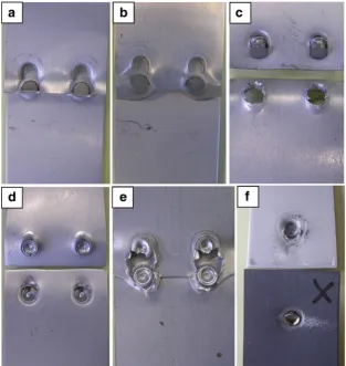
‘Trifurcating rivets’(a solid rivet pierces through the stack and is split into three legs and flared by a fluted die); in the 1980s, semi-tubular SPR rivets with basic tip geometry were devel-oped, and rivet tips started to be contained within the joint button (with ability to achieve water-tight); since the 1990s, the SPR rivets was further developed with reduced web thick-ness and engineered tip geometry to produce uniform rivet flaring and consistent joint strength [24]. Nowadays, self-piercing rivets are normally semi-hollow and manufactured from metal wires by a multi-blow cold-forming process. Figure5shows some typical rivets with a countersunk head and a typical cross-section. Henrob recently also developed a
Fig. 4 A typical four-stage force–displacement curve of an SPR process [46]
new type of fully tubular rivet for joining thick stacks. The through hole in the fully tubular rivet enable more materials to flow upwards inside the rivet cavity to improve bottom re-maining material thickness and the fully tubular rivet also en-able shallow dies to be used to reduce button cracking of bottom less ductile materials, such as high-strength aluminium and aluminium castings [24]. From Fig.6a, it can be seen that when a semi-tubular rivet was used for a thick stack (normally, the combined thickness of the top and the middle materials equal or larger than 5 mm), the punched materials from the top and the middle materials will fully fill the rivet cavity, and when the rivet start to penetrate the bottom material, it will behave more like a hammer, not a rivet with sharp skirt any more. As a result, the bottom material will be smashed and the minimum remaining bottom material thickness will be very small or zero. Also, in order to achieve enough interlock, with a semi-tubular rivet, a deeper die has to be used and this will generate more tearing and cracks on less ductile bottom ma-terials. However, when a fully tubular rivet is used, as shown in Fig.6b, the rivet cavity becomes much larger, and when the rivet reaches the bottom material, the materials filled in the cavity can still be pushed further up, leaving sufficient bottom material under the rivet.
The selection of suitable materials for the rivet manufactur-ing is restricted by the ability of the materials to be cold-formed and heat-treated to a high hardness. Self-piercing rivets are normally made of high-strength steels, such as boron steels, and are heat-treated to various hardness levels depend-ing on the application. Rivets can also be made from alumin-ium alloys, copper, brass and stainless steels, but their
applications are very limited because these materials either cannot be heat-treated to improve their piercing ability or their performance after hardening is poor [7]. In order to increase the recyclability and reduce the galvanic corrosion potential, aluminium rivets were tried for joining aluminium alloy parts [53–55]. Hoang et al. [53] studied the possibility of replacing steel self-piercing rivets with aluminium rivets when using a conventional die. Their results showed that it was possible to join 2 mm AA6060 sheet to 2 mm AA6060 sheet in W temper (solution heat treated) with AA7278-T6 rivets. Reasonable static strengths were achieved as shown in Fig. 7, although the interlock distances were low, ranging from 0.12 to 0.37 mm. Attempts to join higher-strength aluminium alloys or to join AA6060 W with lower-strength aluminium rivets were not successful due to rivet fracture and rivet compres-sion/buckling, respectively. Instead of semi-tubular rivets, Kaščák and Spišák [31] developed some solid aluminium al-loy rivets (no cavity) and used them to join various steel panels with a good joint geometry and strength. Due to the lower strength and hardness of aluminium rivets, their appli-cation will be limited.
Self-piercing rivets for automotive are normally available with two stem diameters: 3.35 mm (nominal 3 mm) and 5.3 mm (nominal 5 mm). The length of self-piercing rivets available ranges from 3.5 to 14 mm. The selection of rivet length is determined by various factors such as the material stack to be joined, the die to be used (different geometries and dimensions) and the rivet diameter and hardness. The rivet length selection guidelines from the European Aluminium Association are as follows: for rivets of 3 mm diameter, rivet
Fig. 5 Typical SPR rivets with countersunk head and a cross-section
length = stack thickness + 2.5 mm; for rivets of 5 mm diam-eter, rivet length = stack thickness + 3.5 mm [56]. Other or-ganizations provided different guidelines. For example, Henrob Ltd. suggests that the rivet length should be 1.5–3 and 2–4 mm longer than the stack thickness for 3- and 5-mm diameter rivets, respectively. Basically, longer rivets will be required to join a thicker stack if the materials to be joined and the stack configuration are similar. Stack configurations can also influence the rivet length selection. Rivets that are shorter than the recommendation may be used for joining a thin top material to a thick bottom material but not for joining a thick top material to a thin bottom material. In the early stages of SPR application, the rivet diameter selection was based on the joint stack thickness, in which thicker stacks would require larger diameter rivets [8]. Nowadays, the influ-ence factors for selecting the appropriate rivet diameter in-clude the required joint strength, the required joint robustness, the accessibility to joining area and the material and stack thickness [57]. Typically, 3-mm rivets are only used for cos-metic joining such as closures. Larger stem diameter rivets, such as 5.5, 6.5 and up to 14 mm, are often used for joints with thick high-strength steel in applications outside of automotive section, where a high rivet column strength is required to prevent buckling. Generally, the joints with a smaller-diameter rivet will have lower strength and robustness for each joint, and riveting of smaller-diameter rivets will require smaller access area and flange size due to a smaller nosepiece. Steel rivets can be delivered in an as-forged state (softest state) or can be heat-treated to various hardness levels. The hardness of steel rivets can be from about 250 Hv (in the as-forged condition) to about 600 Hv. The selection of the rivet hardness is determined by the material stack to be joined. Basically, a harder rivet should be selected for higher strength and harder materials. If a rivet is too soft for a material stack, the rivet will buckle or be compressed during the riveting process; on the other hand, if a rivet is too hard for a material stack, the rivet will exhibit little deformation during the
riveting process, and as a result, the interlock distance will not be sufficiently high to hold the bottom material to provide a high joint strength.
Steel rivets are normally coated to improve corrosion resis-tance and to lubricate the rivet. The coating is required to reduce the friction between the rivet and the material to be joined during the SPR setting process and to prevent corrosion between the rivet and the substrate during service. Common coatings include mechanically plated zinc/tin or zinc/tin/alu-minium coatings, electroplated zinc nickel coating and paints such as Kal-gard, zinc flake and epoxy. Paints can be applied as a top coating over plating or as a two-layer system. The amount of lubrication required from the coating depends on the joint stack and the friction level that can be tuned to achieve the desired amount of rivet flare inside the joint. The amount of corrosion protection required from the coating de-pends on whether the assembly is e-coated after rivet inser-tion. The use of zinc/tin mechanical plating in combination with e-coat has proved very durable in service. Aluminium car bodies with this corrosion protection system have been on the road for more than 15 years without corrosion issues. For assemblies that are not e-coated, a high-performance two-lay-er rivet coating is usually employed, such as zinc-rich base layer combined with a sealing top layer. The growing interest in using SPR in non e-coated assemblies has led to the devel-opment of new rivet coatings capable of providing 1500 h without red rust for rivets set into aluminium plates and placed in salt-spray chambers.
Simulation can be used to design rivets for SPR applica-tions. Xu [58] simulated the influence of yield strength of the rivet material on the setting process. His results showed that when the yield strength of a self-piercing rivet material was too low, the rivet deformed before it could pierce the top sheet, and when the yield strength of the rivet material was too high, the rivet could not be deformed, such that it could not form an interlock within the sheets. To use the advantage of SPR as a cold joining process and to make it suitable for joining small structures, Presz and Cacko [59] scaled down the size of a normal 5-mm diameter self-piercing rivet to a micro-rivet with diameter of 0.7 mm. They simulated the forming process of 4 different types of micro-rivets, and based on the properties of these rivets, they simulated the micro-SPR joining process. Their results showed that these rivets were strong enough to obtain micro-SPR joints with a good joint quality.
3.2 Die
Dies used for SPR are usually made of tool steel. They can have different diameters, different cavity depths and different cavity geometries. Dies can have a cavity with a flat bottom or with a tip in the middle (pipped die), and they can also have a nearly vertical sidewall or a tilted sidewall. The geometry of a
die will influence the rivet setting force and flaring of the rivet tail. Figure8shows some typical dies and a cross-section.
Die cavity diameters need to be larger than the rivet stem diameters, so that during the riveting process, the rivet tail will have enough space to flare inside the die cavity. Generally speaking, die diameter does not have much influence on the flare of the rivet legs if it is large enough; however, it can influence the interlock distance. Dies with larger cavity diam-eters will produce joints with smaller interlock distances if all other parameters are the same. This is due to the fact that the dies with larger cavity diameters have less constraint on the bottom material. So, the diameter of the die cavity cannot be too large. Normally, 3-mm-diameter rivets need smaller diam-eter dies, normally with a cavity diamdiam-eter of 6- or 7- and 5-mm-diameter rivets need larger diameter dies, normally with a cavity diameter no less than 8 mm.
Dies for SPR may have a cavity with a flat bottom or a pip in the middle with different geometries and dimensions. Normally, a pip in the die can enhance rivet deformation and increase the interlock distance, but it will also introduce larger plastic deformation of the bottom sheet and will require a larger setting force. So, a die with a pip will produce more severe cracks when a less ductile material is used as the bot-tom material.
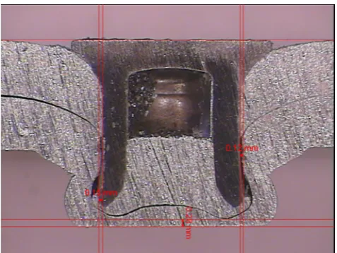
Dies for SPR may have different cavity depth. Normally, a deeper die will provide less support to the bottom material, and as a result, less force will be required to set the rivet, and a smaller interlock distance will be generated. In addition, a deeper die will introduce larger plastic deformation in the bottom sheet and may introduce necking problems at the joint button, as shown in Fig.9and cracking issue for less ductile materials. Consequently, in order to avoid severe cracking, a deep die will not be suitable when a less ductile material is used as the bottom material.
Research by Li et al. [60] showed that when a less ductile metal is used as the bottom material, it is better to use dies with a shallow cavity and if possible, use dies with a tilted sidewall to avoid excessive plastic deformation and cracking. They demonstrated that even though the high-strength aluminium alloy AA6008 had good ductility with elongation of more than 20%, when it was joined as the bottom material using a
die with a vertical sidewall and a depth of 2 mm, severe cracks were generated at the joint button. To reduce the size and number of cracks to an acceptable level, a die with a shallower depth and a tilted sidewall was required to join the AA6008 as the bottom material. Apart from reducing cracking, Sunday [4] also pointed out that a tilted sidewall in a die can facilitate the die release at the end of riveting.
Proper die design can be used to improve the rivetability of some material stacks. To improve the capability of the SPR process, Iguchi and Ohmi [61] designed a die that has the capability to join a thick sheet to a thin and less ductile sheet as the bottom material. By using a spring-loaded sliding pin in the centre of the die, the excess denting of the top thick sheet could be prevented and the penetration of rivet into the bottom sheet was increased, as shown in Fig.10.
Simulation can also be used to optimise the profile of the die for a particular stack. Mori et al. [62] conducted simulation using LS-DYNA to optimize the profile of the die to join an ultra-high-strength steel to an aluminium alloy. By increasing the diameter of the cavity and reducing the height of the pro-jection (tip), the punch force is reduced and thus plastic defor-mation of the rivet when it is piercing through the upper sheet is prevented. Further work was done by Mori et al. [63] to improve the rivetability of multi-layer steel and aluminium alloy joints.
3.3 Setting force
During the SPR process, a relatively high force, ranging from 20 to 100 kN, is required to set a rivet into a material stack to form a joint through pushing, punching or other methods. The joint will need to satisfy all the geometry and strength criteria, such as lap shear strength, T-peel strength, rivet head height, interlock distance and minimum remaining bottom material thickness, so the force cannot be too high or too low. If the force is too low, the rivet head may protrude out of the top flush surface that is not good for cosmetics. It may also facil-itate corrosion due to the existence of a big gap, into which water may penetrate. In addition, a low setting force may lead to a short interlock distance, which will lead to a joint with low strength. If the force is too high, the indentation caused by the
rivet head may be too large and the minimum remaining bot-tom material thickness may be too small. A large indentation may damage the top sheet and reduce the strength of the top sheet to resist the rivet from being pulled out.
Hill [8] reviewed the parameters that could influence the rivet setting force. The parameters studied include the rivet shank diameter, the rivet shank end form (tip geometry), the friction between rivet and sheet materials, the die shape, the sheet material thickness and hardness and the rivet hardness. Hou et al. [46] also studied the parameters that could affect the setting force, including the die geometry, the rivet length, the material stack, the planar misalignment (gap between the sheet materials) and the axial misalignment (between the rivet gun and the die). Their results showed that planar misalignment could change the joint features and reduce the setting force, but slight axial misalignment did not have obvious influence on the setting force. Research from Kim et al. [64] showed that the strength and hardness of substrates had large influence on the rivet piercing force for the top sheet; however, in the fol-lowing stages, the rivet setting force was mainly determined by the force required to deform the rivet. Their results also
showed that rivet setting force could be reduced at higher joining temperatures.
With the increasing use of low-ductility bottom sheet ma-terial and higher-strength top sheet mama-terial, higher rivet inserting forces are required. Insertion force of 80 kN is now common, and new SPR systems are tending to employ stron-ger and stiffer C frames and servo actuators with higher-force capabilities. For joining high-strength materials, compared to soft aluminium, the rivet setting tool alignment becomes more important and the process window usually becomes smaller. Today, it is widely agreed that the value of the setting force depends on the sheet material strength, the material and stack thickness, the rivet length, the rivet tip geometry, the rivet coating, the rivet hardness, the die geometry, etc. Generally speaking, if other parameters are kept the same, harder/ stronger sheet materials, more shallow dies or dies with a pip, larger rivet diameters, higher friction between rivet and sheet materials, longer or harder rivets and rivets with blunter tip geometries will require higher setting forces.
3.4 C-frame
The SPR process needs a high setting force typically in the range of 20 to 100 kN, much higher than those used for spot welding, in the range of 1 to 10 kN; tool alignment for an SPR system also needs to be better than that for spot welding. As a result, the C-frame needs to be stronger and more rigid. Information provided by industry suggested that the deforma-tion of a C-frame during a setting process needed to be re-stricted within 7 mm along the loading line with an angular deflection less than 1° [45]. Other parameters that are impor-tant for the C-frame include the throat depth and weight. The throat depth of a C-frame determines the lateral access ability, and the weight of a C-frame will determine its automation ability; the mobility of the robot with the C-frame is mounted on and the cost of automation. For easy automation, research has been undertaken to reduce the weight of the C-frame. Westgate et al. [45] developed a lightweight deep-throat C-frame for an early robot-mounted hydraulic SPR system.
[image:10.595.51.290.51.230.2]Fig. 9 An SPR joint with over-deep die (small interlock distance and joint button necking)
[image:10.595.171.545.573.715.2]Nowadays, electric-servo SPR systems are preferred, which are much lighter than hydraulic SPR systems and can also eliminate the need for connections to high pressure hoses. As a result, the requirement on the weight of the C-frame is reduced and the automation of the SPR process becomes eas-ier and less costly.
4 SPR joint quality criteria
In order to produce strong and reliable SPR joints, different users of the technique, including automotive manufacturers, have set up different joint quality criteria. Among these criteria, there are three main aspects that need to be controlled, and they are the rivet head height, the interlock distance and the minimum remaining bottom material thickness (Tmin), as
shown in Fig.11. The rivet head height is important for the cosmetic appearance, the tightness of the joints, the gaps be-tween the rivet head and the top sheet, and the damage of the rivet to the top sheet, etc., and consequently, the joint strength. The interlock distance is the most important joint quality, as it will determine the locking strength between the rivet and the bottom sheet. Although the minimum remaining bottom ma-terial thickness does not have large influence on the joint strength, it is important for noise, vibration and harshness (NVH) and corrosion. Common practice by carmakers is to locate the rivets head inside the car and the joint buttons on the underside of the car in wet areas and therefore avoiding rivet breakthrough by keeping a minimumTminhas obvious
corro-sion prevention advantages. Other joint quality aspects are also considered by different organizations, such as the cracks at the joint buttons, the buckling of the rivet, the cracks in the rivets, the gaps between the rivet head and the top sheet and the gaps between the sheet materials, etc.
Joint quality criteria are substrate material-related. For a joint with steel as the bottom sheet/locking sheet, the mini-mum required interlock distance can be reduced because steel
is stronger than aluminium [65]. According to a leading auto-motive manufacturer, the joint quality criteria include a rivet head height between 0.3 and−0.5 mm (a negative rivet head height implies that the rivet head is below the flush surface of the top sheet), an interlock distance of at least 0.4 mm for joints with an aluminium alloy as the bottom sheet and at least 0.2 mm for joints with a steel as the bottom sheet and aTminof
at least 0.2 mm [66]. Generally speaking, the lower the rivet head height, the higher the interlock distance will be, as re-ported by Han et al. [66] for mixed aluminium and steel joints and Li et al. [65] for aluminium alloy joints.
5 Suitable materials for SPR joining
One of the advantages of SPR is that it can be used to join similar and dissimilar materials. While SPR is widely applied for joining aluminium structures, it can also be used to join other materials and mixed materials, including aluminium, steel, magnesium, copper, plastics, wood, composites etc. Aluminium alloys that can be joined by SPR can be wrought, extruded and cast alloys. The grades of wrought aluminium alloys used in automotive body applications include 5xxx, 6xxx, etc. Steels that can be joined by SPR include mild, high-strength and advanced high-strength steels.
The general requirements for materials that can be joined by SPR include the following: (i) materials need to have suf-ficient ductility, especially for bottom materials that are next to the die, so severe cracks will not be generated at the joint buttons; (ii) materials need to have a hardness/strength much less than that of the rivet, so that the rivet can pierce through/ into the material and form a sufficiently high interlock dis-tance without excessive compression or buckling. Brittle ma-terials may be able to be joined when used as the top or middle material, but not as the bottom material on the die side without assistance from other sources, such as heating.
For a stack with two layers, the ratio between the thickness of the top and bottom materials can influence the rivetability of the stack and the strength of the joint. Normally, better rivetability and strength will be achieved when a thinner sheet is used as the top material and a thicker sheet is used as the bottom material. However, due to access limitations and other issues, sometimes rivets can only be pierced from the thicker sheet side, and in this case, careful design/selection of rivets and dies is required to achieve the desired joint quality.
The study of the rivetability of various material combina-tions has been the subject of several investigacombina-tions. Abe et al. [14] studied the joinability of an aluminium alloy to mild steel, and their results showed that to join the aluminium alloy as the top sheet and the steel as the bottom sheet, the top sheet need-ed to be thinner than the bottom sheet. This was the result from an earlier research with an old SPR system; however, with the state-of-art SPR system, high-quality joints with thick
aluminium on the top and thin steel on the bottom can also be achieved, as shown in Fig.12. Abe et al. also demonstrated that to join the steel as the top sheet and the aluminium alloy as the bottom sheet, a better joinability can be achieved than to join the aluminium alloy as the top sheet and the steel as the bottom sheet. Chung and Kim [67] studied the fatigue perfor-mance of aluminium/mild steel SPR joints. Same thickness of 1.5 mm was used for AA5052 H32 and cold rolled mild steel. Their results showed that the joints with steel as the top sheet had better static lap shear strength, but the joints with the steel as the bottom sheet had better fatigue strength. Mori et al. [62] studied the feasibility of joining an ultra-high-strength steel to an aluminium alloy by SPR. They found that if the rivet was not hard enough, joint defects from rivets could occur, such as the rivet fracture, the rivet compression and the rivet bending, as shown in Fig.13. These rivet defects will normally occur when the rivet is too soft for the materials to be joined. With the optimized rivets and dies, they then successfully joined the SPFC980 ultra-high-strength steel (tensile strength around 980 MPa) to AA5052 H34. Another example of rivet failure by compression and fracture during the riveting process was shown by Hoang et al. [53], when they joined aluminium alloys with aluminium rivets.
The joining of magnesium alloys using SPR has been stud-ied by various researchers. Magnesium alloys have low duc-tility at room temperature due to their hexagonal lattice struc-ture, but their ductility increases with the increase of temper-ature. Research by Hahn and Horstmann [68] showed that after locally heating magnesium alloy AZ31 to 280 °C using induction heating, it was possible to join AZ31 as the top and/ or bottom materials by SPR and clinching. Durandet et al. [69] proposed to use laser-assisted SPR to join magnesium alloys. When wrought strips of AZ31B-H24 magnesium alloy with a thickness of 2.35 and 3.2 mm were heated above 200 °C, the
AZ31 could be successfully self-piercing riveted without cracks. Henrob has produced crack-free SPR joints for mag-nesium alloys with their patented ultrasonic assisted SPR pro-cess [70].
Sjöström [71] studied the feasibility of joining stacks with a cast magnesium alloy (AM60B) and an ultra-high-strength steel (Dogal DP800) by SPR. They found that the ductility of the magnesium alloy limited the use of SPR; severe crack-ing of the magnesium alloy sheet occurred in all tested con-figurations, but the number of cracks could be reduced by local heating of the magnesium alloy substrate. Local heating of the magnesium alloy substrate not only suppressed the cracking of the magnesium alloy when it was used as the bottom sheet, but also improved the setting of the rivet head and promoted the interlocking. To achieve sufficient interlock distance between the rivet and the sheet materials and obtain an optimal joint strength, the thicker magnesium alloy sub-strate needed to be placed on the die side.
Luo et al. [72] studied the rivetability of magnesium alloys to aluminium alloys. Table1shows the mechanical properties of the alloys that were used. The results showed that when used as the top material, the die-cast magnesium alloy AM50 could be self-piercing riveted to the extruded AA6063, but when the AM50 was joined as the bottom material, severe cracks occurred at the joint buttons, as shown in Fig. 14. Because AA5754 and wrought magnesium alloy AZ31 had large elongations, 26 and 21%, respectively, it was possible to join them as both the top and bottom materials.
Apart from the influence of local heating on the rivetability of magnesium alloys, Wang et al. [73] also studied the influ-ence of local heating on the joint strength and the failure modes. They found that when riveting 2 mm AZ31 to 2 mm AZ31 at room temperature, severe cracking occurred at the joint button, but when the AZ31 was pre-heated to 180 °C or above, the cracks were eliminated. They also observed that by pre-heating the AZ31, the lap shear strength of the joints could be increased and the failure of joints during lap shear tests changed from tearing of the bottom sheet to rivet being pulled out from the bottom sheet. SPR had also been used in combi-nation with adhesive to join magnesium alloys to achieve a higher joint strength [74].
The variation in the results presented by different re-searchers on the rivetability of magnesium alloy AZ31 may be caused by the different mechanical properties of the alloy. AZ31 can be produced through different processes, such as die-casting, extrusion and rolling, resulting in different ductility.
Apart from joining aluminium, magnesium and steel, SPR has also been used to join copper and titanium. Copper sheets have excellent ductility, and SPR has been successfully used to join aluminium to copper [75] and copper to copper [76]. Titanium alloys have limited form-ability at room temperature. However, when they were
heated to above 700 °C, they could also be successfully joined by SPR [77,78].
SPR has also been tried to join sandwich materials. Pickin et al. [79] demonstrated that it was possible to join a sandwich material (0.2 mm steel + 1.6 mm polymer + 0.2 mm steel) to a 2-mm-thick aluminium alloy by SPR. Unpublished results from the University of Warwick also showed that it was pos-sible to join steel/polymer sandwich materials to achieve a high joint strength.
In addition, the feasibility of using SPR to join com-posites to aluminium alloys has been investigated. Fratini and Ruisi [80] studied the feasibility of a joining glass fibre composite to an aluminium alloy, and they found that it was possible to join them by SPR. However, due to the brittle nature, the glass fibre composite could only be used as the top material, as shown in Fig.15. Research by Di Franco et al. [81] showed that SPR could be used to join a carbon fibre reinforced polymer (CFRP) composite to aluminium alloys with reasonable joint strength. SPR was used by Settineri et al. [82] to join polymer and polymer-based composites to aluminium alloys. Their re-sults demonstrated that SPR appeared competitive for metal/polymer joining as to joint strength and cost. Research was also carried out by Zhang and Yang [83] to study the joinability of various thermal plastic polymer PA6-based materials and AA5754. Their results showed that when PA6 and its glass fibre or carbon fibre rein-forced composite were used as the bottom material, severe cracking or bottom sheet penetration would happen and the carbon fibre reinforced thermal plastic could not be
used as the top sheet due to fracture during the SPR rivet inserting process. Unpublished Research from the University of Warwick has also demonstrated that it was possible to join composites to aluminium alloys by SPR and by a combination of SPR and adhesive. Di Franco et al. [84] demonstrated that by combining SPR and ad-hesive bonding, joints with a high strength, a high stiff-ness and high-energy absorption could be achieved. Fiore et al. [85] studied the mechanical performance of a Basalt fibre-reinforced polymer to aluminium alloy AA6086 mixed joints. Their results showed that the strength of the self-piercing riveted joints was lower than that of the adhesive-bonded joints. Gay et al. [86, 87] studied the fatigue performance of glass fibre reinforced composites/ aluminium SPR joints, and their results showed that the SPR joints with domed rivets performed better than the joints with countersunk rivets and SPR was proved to be a durable joining method for joining composites to alumin-ium alloys in the automotive industry.
The SPR process for joining composites to aluminium alloys was also studied through experiments and simula-tion. Di Franco et al. [88] studied the SPR process for joining a CFRP to an aluminium alloy through experi-ments and finite element modelling. Later, they reviewed their research with additional emphasis on understanding the failure mechanisms [81, 89]. Results showed that ap-plied oil pressure of the electro-hydraulic riveting system had significant influence on the joint strength. They found that the SPR process could be simulated using the finite element code DEFORM™ 2D, and the predicted joint features and force–displacement curve matched well with the experimental results. Mechanical tests showed that during static lap shear tests, all specimens failed by rivet being pulled out from the top CFRP panel, and during a lap shear fatigue test, specimens failed at the top CFRP panel around the rivet head or at the bottom aluminium alloy sheet along the joint button.
In summary, SPR can be used to join composites, as top or middle material, to metal materials. However, it is clear that the SPR process can damage the reinforcing fibres and cause delamination during the riveting process, which will reduce the strength of the composite. Also for
Fig. 13 Possible joint defects for joining an ultra-high strength steel to an aluminium alloy by SPR [62]
Table 1 Typical mechanical properties of the aluminium and magnesium alloys [72]
Alloy Yield strength, MPa
Tensile strength, MPa
Elongation, %
Extruded AA6063-T6 215 240 12
Die-cast AM50 125 210 10
Sheet AA5754-O 100 220 26
this reason, traditional SPR is not suitable to join com-posites as the bottom material. Researchers are trying to solve the issues faced by SPR when joining plastics and composites. Henrob Ltd. [90] developed a new SPR pro-cess using a pre-drilled washer between the rivet head and the top sheet and a non-drilled washer below the bottom sheet; in this process, the rivet pierces through both the top and bottom sheets and flares into the lower washer. This process was used to join Lotus Elan’s glass fibre-reinforced plastics (GRP) floor pan. Ueda et al. [91] in-troduced a modified SPR process, in which two pre-drilled washers were introduced, with one between the rivet head and the top of the stack and the other between the bottom of the stack and the bended rivet skirt. By setting the rivets this way, the delamination of the com-posites was sufficiently suppressed; however, there might be issues for aligning the rivet with the washers and the additional weight and cost of the washers.
Apart from fibre damage, delamination and cracking, differential thermal expansion or contraction is another issue on joining composite-contained stacks by SPR. For joining CFRP composite by SPR, there is another chal-lenge, corrosion between CFRP and rivets, due to the cathodic nature of CFRP. Corrosion of fasteners in CFRP is a big issue. Usually, the fasteners are required
to be made of stainless steel or more exotic materials like titanium to minimize the corrosion.
6 Mechanical performance of SPR joints
6.1 Contributing elements of static strength
Knowing the contributing elements of the static strengths of an SPR joint is very important for understanding and improv-ing the joint strength. Hill [8] proposed that the lap shear strength of an SPR joint should be a combination of a direct shear force and a frictional force at the sheet interface. However, he also suggested that the strength of an SPR joint was difficult to predict, because the compression force in SPR joints, essential for friction, was not high and would be unpredictable.
A number of other researchers have also suggested that the frictional forces between the sheet materials and between the rivet and the sheet materials are very important in the deter-mination of the static strength of SPR joints. Han and Chrysanthou [92] demonstrated that the residual compression pressure from the rivet setting process could influence the frictional force between the rivet and the sheet material, and consequently, the static strength. Results from Han et al. [92,
93] also showed that sheets with different surface conditions would require different rivet setting forces and result in differ-ent joint strength and failure modes due to differdiffer-ent friction behaviour at the interfaces. Later, Li et al. [94,95] pointed out that the friction between the top and bottom sheets, around the tip of the punched hole in the top sheet, was very important for the static lap shear strength.
[image:14.595.52.288.575.691.2]In the case of SPR with two layer of materials, it is believed that the strength of an SPR joint is a combination of (i) the force to deform the top material underneath the rivet head or the bottom material locked by the rivet tail, (ii) the force to deform the rivet, (iii) the frictional force between the rivet head and the top sheet or between the rivet tail and the locked bottom sheet and (iv) the frictional force between the top and
Fig. 14 The cross-section of an SPR joint with extruded AA6063 and die-cast magnesium AM50 [72]
bottom sheets, especially around the tip of the punched hole in the top sheet. However, the influence of the frictional force between the top and bottom sheets on T-peel and cross-tension strength is not significant.
6.2 Influence of material stacks
The influence of the sheet materials on joint strength can be from the sheet thickness, the stack thickness, the stack orien-tation and the material strength. Since the strength of an SPR joint was not only determined not only by the substrate strength but also the joint features. In this section, when study-ing the influence of material stacks, it has to be assumed that for all stacks in comparison, the process parameters have been optimised to achieve high-quality joint features.
When the top and bottom material of the stacks is the same material, the influence of material stacks on joint strength is more straightforward. Madasamy et al. [96] studied the static and impact behaviours of some aluminium alloy SPR joints, where the sheet thickness was 1, 2 and 3 mm. They found that the joint strength was sensitive on the thickness of the top sheet. Further studies from Madasamy et al. [97] investigated the crash performance of the aluminium alloy and steel rails joined by SPR. It was found that for the aluminium alloy crash rails, the thickness of the sheet material was the main factor that influenced the performance, and for the steel crash rails, the sheet material thickness, the impact speed and the temper-ature all had significant influence on the impact performance. Research by Hill [8] showed that for both the steel and alu-minium alloy SPR joints, the lap shear and cross-tension strength increased with the increase of the stack thickness within the range studied, and research by Taylor [98] showed similar results. It is believed that the results reported by these authors are for stacks with the top and bottom materials of similar thickness. Porcaro et al. [99] also demonstrated that the strength of the SPR joints of aluminium extrusion AA6060 increased with the increase of the stack and sheet material
thickness, as shown in Fig. 16b, but the joint strength was not influenced by the width of the plate. Li and Fatemi [100] studied the mechanical performance of the aluminium alloy SPR joints in T-peel/coach peel configuration. Their results showed that the static T-peel strength of the SPR joints nor-mally increased with the increase of the stack thickness, ex-cepting that the 3 + 3 mm (first sheet as the top sheet and the second sheet as the bottom sheet) SPR joints had poorer static T-peel strength than the 2 + 3 and 2 + 2 mm specimens. Li and Fatemi pointed out that sheet thickness was not the only factor that influenced T-peel strength, and they believed that the higher stiffness against plate bending for the 3 + 3 mm spec-imens and the subsequent lower friction and higher shear forces between the contact surfaces were the reason that caused the lower strength of that stack. Li and Fatemi neither disclosed the details of the rivets used for the different material stacks, nor presented the joint features, such as the interlock distance and the rivet head height. It is possible that the rivet used for the 3 + 3 mm SPR specimens did not generate a sufficiently high interlock distance or the rivet head had deeper penetration in the top sheet, leaving the joint less re-sistant to the rivet being pulled out. Khanna et al. [101] studied the mechanical properties of self-piercing riveted AA6111 al-uminium alloy joints of various thickness combinations. Their results showed that for joints with equal top and bottom ma-terial thickness, the static and fatigue strength (lap shear and T-peel) both increased with the increase of sheet material ness. For joints with unequal top and bottom material thick-ness, the strength of the joints was greatly determined by the thinner sheet, and their strength will normally be weaker than that of the stacks with the same total stack thickness but equal to the top and bottom material thickness. As to stacks with high top/bottom material thickness ratio, their strength will be much weaker.
When the top and bottom materials of stacks are from dif-ferent materials, the influence of the stack and sheet material thickness on joint strength will be more complicated. Li et al.
[60] evaluated the joint quality and the mechanical strength of a high-strength aluminium alloy SPR joints. The results showed that the static lap shear and T-peel strength of the joints increased greatly with the increase of the top material (AA5754) thickness, but the increase of bottom material (AA6008) strength, from 195 to 250 MPa, only had marginal influence on the static joint strength. It was also demonstrated that when the AA6008 sheet was joined as the bottom mate-rial, a thinner top material could make the cracking of the bottom AA6008 more severe than a thicker top material. Results from Porcaro et al. [99] showed that the stacks with higher strength material will normally have higher joint strength, as shown in Fig.16a.
Just like material types and grades, substrate work harden-ing also can affect SPR joint strength. Many parts used in automotive body structures are stamped, and during the stamping process, materials are strained and work-hardened. In order to determine the influence of stamping, Han et al. [102] studied the influence of pre-straining on the mechanical behaviour of aluminium alloy joints. The stack they studied had 2 mm AA5754 as both the top and bottom sheets, and they compared the static and fatigue lap shear strength of the specimens with the original AA5754 and the AA5754 with 3, 5 and 10% pre-strain. They found that the pre-straining im-proved both the static and fatigue strength of the joints, as shown in Fig.17. Similarly, age hardening can increase the substrate material strength and subsequently the SPR joint strength. When doing strength comparison, joint strength be-fore and after age hardening need to be stated clearly.
The influence of the stack orientation (rivet setting direc-tion) on joint strength is mainly due to the resulting different joint features and for mixed material stacks, the strength dif-ference of the top and bottom materials. Madasamy et al. [96] studied the influence of stack orientation on the joint strength of aluminium stacks. An aluminium alloy with different thick-ness of 1, 2 and 3 mm was used, and their results showed that with the same stack thickness, setting the rivet through the thinner sheet side would result in the joint having higher strength and energy absorption. Similarly, Porcaro et al. [99] presented that the use of a thicker material as the bottom sheet would normally produce the joints with higher strength than the use of a thinner material as the bottom sheet, as shown in Fig.16b. Sun [103] and Stephens [104] studied the influence of stack orientation on the joint strength of mixed aluminium and steel stacks. Figure18 shows the cross-sections of two stacks with reversed orientations. Their results showed that the stack of joining 1 mm high-strength low-alloy steel (HSLA) 350 to 2 mm AA5182 O had better strength and energy ab-sorption than the reversed stack with 1 mm HSLA 350 as the bottom materials in lap shear, T-peel and cross-tension, as shown in Fig.19. However, they also showed that for a dif-ferent pair of stacks with DP600 and AA5182 O, the stack with DP600 as the bottom material had lower lap shear
[image:16.595.308.545.52.376.2]strength but higher T-peel and cross-tension strength. Generally speaking, stack orientation will influence joint
[image:16.595.307.545.449.680.2]Fig. 17 Influence of the amount of pre-straining on the static and fatigue lap shear strength of the single-rivet SPR joints [102]
strength, but which orientation is better will depend on joint features, base material strength, loading directions and failure modes. However, it is believed that joining a stack with a thinner material as the top material will be easier and have a larger process window, since it is easier to achieve enough interlock without over-thinning or penetrating the bottom material.
In order to increase the SPR joint strength of a thicker aluminium joined to a thinner steel, Lou et al. [43] used resis-tance spot welding after SPR. Their results showed that by doing this, a 12% lap shear strength increase could be achieved.
Based on the reported research, the actual strength of an SPR joint will depend on the stack orientations (rivet setting direction), the material and stack thickness, the sheet material strength, the top and bottom material thickness ratio, etc. Typically, SPR joint strength increases with the increase of the sheet material thickness or the stack thickness, for stacks with similar top and bottom materials and similar top and bottom material thickness. For joints with unequal thickness of the top and bottom materials (similar strength), the strength of the joints will be greatly determined by the thinner sheet and the joint strength will normally be higher if the thick material is used as the bottom material. When materials with different strength are used, for a similar stack configuration, the joints with higher strength materials will normally have higher strength, and similarly, pre-straining of materials can also increase the joint strength.
6.3 Influence of rivets and dies selection
SPR joints with different rivets may have different joint strengths due to the different rivet diameters, rivet hardness and rivet lengths. The influence of the rivet tip geometry on joint strength will be discussed separately in a later section. Results from Hill [8] and Taylor [98] showed that for both steel and aluminium alloy SPR joints, the joints with larger-diameter rivets exhibited higher shear and tension strength. Madasamy et al. [96] demonstrated that the joints with 5-mm-diameter rivets had higher strength and higher energy
absorption than the joints with 3-mm-diameter rivets. These observations are probably due to the increased strength of rivet itself, the increase interlock distance and the increased rivet head size. Influence of the rivet length on joint strength is mainly caused by different joint features, such as the rivet head height, the interlock distance and the minimum remain-ing bottom material thickness (Tmin). SPR joints with longer
rivets normally have higher joint strength and energy absorp-tion due to a larger interlock distance, providing that the rivet head height andTminare similar.
In order to further reduce vehicle weight, new lightweight or high-strength materials are introduced into the structure, but some of them have higher tendency to crack when they are joined by SPR. Li et al. [105] studied the influence of the die profile and the joint button cracks on the mechanical perfor-mance of the self-piercing riveted high-strength aluminium alloy joints. The results showed that due to the large bending and tension deformation, the dies with a deep cavity and/or sharp corners would tend to cause severe cracks for some materials (such as the high-strength aluminium alloy AA6008T61), when they were joined as the bottom material, as shown in Fig.20. They also found that a thinner material had a lower tendency to crack than a thicker material due to a lower bending stress. Their study suggested that cracks on joint buttons could reduce the static and fatigue lap shear strength but had no obvious influence on the static and fatigue T-peel strength.
One of the joint defects that may occur is the bottom sheet breakthrough (rivet penetrates the bottom sheet), which may be caused by an overlong rivet, an over-high setting force or a wrong die used. Han et al. [106] studied the effect of the bottom sheet breakthrough on the mechanical behaviour of the self-piercing riveted aluminium AA5754/HSLA joints. Two-millimitre-thick AA5754 aluminium alloy and 1-mm-thick HSLA were used in the study. Their results showed that the breakthrough in the bottom sheet had a minor effect on the shear strength of the joints, but there was a significant effect on the peel strength. The breakthrough led to the change of failure modes for the lap shear tests. During the lap shear tests, the joints with breakthrough failed by tearing of the bottom sheet, and the joints without breakthrough failed by the rivet being pulled out from the bottom sheet; during T-peel tests, all specimens failed by the rivet being pulled out from the bottom sheet. The joints with breakthrough had larger interlock dis-tances that determined the rivet pull-out strength from the bottom sheet, but lower bottom sheet strength against tearing. As a result, the joints with breakthrough had slightly lower lap shear strength, but much higher T-peel strength. Their results also showed that the breakthrough slightly affected the fatigue life and accelerated the corrosion behaviour of the self-piercing riveted joints, because the breakthrough facilitated the penetration of corrosion media through the broken bottom sheet.
Rivets and die are two of the key process parameters of SPR. To ensure good joint features for the joints, selection of the right rivet and die for a particular stack is crucial during process evaluation stage. The influence of rivet and die selec-tion on SPR joint strength is mainly from the difference of the resulting joint features. Most rivet types are usually available as a‘family’in a range of length and hardness options. During the parameter optimisation process for a particular stack, nor-mally, a potential rivet/die combination will be tried first, and the riveted joint will be evaluated. Then, the rivet with the next hardness level or the next-length increment or different die will be tried in order to make a further optimisation until an optimised parameter combination is achieved. Generally, joints with larger-diameter rivets normally have larger strength than those with smaller-diameter rivets, since rivets with a larger diameter are stronger themselves and they have larger contact areas with the sheet materials. The larger contact areas can increase the frictional force between the rivet and the sheet material. When a different rivet and die are used to produce a joint, the joint will have different joint features, such as interlock distance, rivet head height,Tminand bottom sheet
breakthrough, and as a result, the joint will have different strengths.
Although SPR is not as flexible as RSW, modern SPR systems are providing more flexibility with multiple rivet feeds and die changers. These improvements make it possible that one SPR system can use different rivets and dies, instead
of the same rivet and die, for a large number of different stacks. This is an important step forwards for SPR technology, and with this flexibility, more stacks can be joined with optimised rivet and die and the SPR systems will have more capability to cope with the typical range of production variables.
6.4 Influence of setting force
In order to satisfy the joint quality criteria, for a specific com-bination of a material stack, a rivet and a die, only certain range of setting force can be used. Different setting forces will produce joints with different joint qualities, and as a result, with different mechanical performances. Researches have been conducted to investigate the influence of setting force on the mechanical performances of SPR joints.
[image:18.595.181.546.50.352.2]Li et al. [65] studied the influence of the setting velocity/ force on the performance of 2 mm AA5754 + 2 mm AA5754 SPR joints. The results showed that an over-high velocity would leave a big dent on the top sheet and an over-low velocity would leave the rivet head protruding out of the top sheet. In their research, all the lap shear specimens failed by the rivet being pulled out from the bottom sheet and all the T-peel specimens failed by the rivet being pulled out from the top sheet. From these observations, they proposed that for the stack studied, the static lap shear strength was determined by the interlock, while the static T-peel strength was determined

![Fig. 18 The cross-sections of SPR joints with different stack orientations1 mm HSLA 350 + 2 mm AA5182 O (modified from [but the same rivet and die, a 2 mm AA5182 O + 1 mm HSLA 350 and b103])](https://thumb-us.123doks.com/thumbv2/123dok_us/9438813.451203/16.595.307.545.449.680/sections-joints-different-stack-orientations-modified-rivet-hsla.webp)
![Fig. 20 The cross-sections andbutton images of the SPR joints(3.0AA5754 + 2.5AA6008 T61215 MPa) with a, b the deep andsharp corner die and c, d theshallow and tilted sidewall die(modified from [105])](https://thumb-us.123doks.com/thumbv2/123dok_us/9438813.451203/18.595.181.546.50.352/sections-andbutton-images-joints-andsharp-theshallow-sidewall-modified.webp)
![Fig. 25 Influence of edge distance on the lap shear strength forspecimens with coupon width of 48 mm [94]](https://thumb-us.123doks.com/thumbv2/123dok_us/9438813.451203/22.595.183.544.52.241/fig-influence-distance-shear-strength-forspecimens-coupon-width.webp)
![Fig. 27 The lap shear fatigue S–N curves for the specimens withdifferent edge distances [124]](https://thumb-us.123doks.com/thumbv2/123dok_us/9438813.451203/23.595.306.544.52.211/fig-shear-fatigue-curves-specimens-withdifferent-edge-distances.webp)
![Fig. 29 The cross-sections of thehardness level 2 sharp rivet [hardness level 2 blunt rivet andSPR joints with different rivets, ahardness level 1 blunt rivet, bhardness level 1 sharp rivet, c d125]](https://thumb-us.123doks.com/thumbv2/123dok_us/9438813.451203/24.595.180.544.438.709/sections-thehardness-hardness-joints-different-rivets-ahardness-bhardness.webp)
![Fig. 30 An illustration of different stack configurations for lap shear tests [126]](https://thumb-us.123doks.com/thumbv2/123dok_us/9438813.451203/25.595.179.546.60.125/fig-illustration-different-stack-configurations-lap-shear-tests.webp)
![Fig. 33 The remaining static T-peel strength of the specimens after thefatigue for different cycles with maximum load of 1.8 kN [95]](https://thumb-us.123doks.com/thumbv2/123dok_us/9438813.451203/26.595.306.546.51.211/remaining-static-strength-specimens-thefatigue-different-cycles-maximum.webp)