r
),
DIS,KETTE '" ,
SYSTEM, \: "',
" " j ",
'REF~'RENCE
',', ,,'
' ,',
MANUAL,'"
THE STANDARD OF EXCELLENSE IN MICROCOMPUTER
SYSTEMS ~
IMSAI
. J T .November, 1978
The information in this document is subject to change without notice and should not be
construed as a commitment by IMSAI Manufacturing Corporation. IMSAI
Manufacturing Corporation assumes no responsibility for any errors that may appear in this document.
DISKETTE SYSTEM REFERENCE MANUAL
Copyright (C) 1978, IMSA I Manufacturing Corporation
No part of this document may be copied or reproduced in any form or by any means withodt the prior written consent of IMSAI Manufacturing Corporation.
The postage prepaid READER SUGGESTION form enclosed with this document reque'sts the user's critical evaluation to assist us in preparing future documentation.
.,.r
DISKETTE SYSTEMS REFERENCE MANUAL
TABLE OF CONTENTS
Section I INTRODUCTION DSK -1
Section II DISKETTE SYSTEMS, GENERAL
2 -1 Components and Interface
2 - 1.1 Controller DSK - 2
2 -1.2 Drive
2 -1.3 Media
2 - 1.4 Data Transfer Mechanism DSK - 3
Programmed Data Transfer Interrupt Driven Data Transfer
DMA Data J"ransfer DSK -4
2-2 Formats and Encodation
2 .. 2.1 TriGks and Sectors
,. 2 - 2.2 Data Formats DSK -7
2 - 2.3 Data Encodation DSK ... 9
2 - 2.4 Bit Cells
2 - 2.5 Synchroniza tion DSK - 12
F M Synchroniza tion DSK - 13
MFM Synchronization DSK - 14
2-3 Write and Read Processes D5K - 16
2 - 3.1 Access Conventions
Byte Commands and Command Strings DSK - 17
Access Schema r DSK - 18
2 - 3.2 Read/Write Sequences DSK - 20
Write Operation DSK - 21
Read Operation
2 - 3.3 Error Handling DSK - 22
Section III IMSAI DISKETTE SYSTEMS DSK - 23
3 -1 General
3-2 Configurations
3 - 2.1
Controllers FIF Controller MDIO Controller010 Controller
3 - 2.2 Hardware Compatibilities DSK - 24
3-3 Tr ansae tions DSK - 32 3 - 3.1 Byte Commands
3 - 3~2 Command Strings
DSK - 34 Byte Definitions
Command Types 3 - 3.3 Accessing the Controller
DSK - 40 Parameter Set Up
Command Call DSK - 41
Status DSK - 42
Error Codes
3-4 System I nitializa tion
USK - 44
Section IV FIF CONTROLLER
FIF - 1 4 -1 Introduction
4-2 Functional De scription
4-3 Da ta Transaction Processes
FIF - 5 4-4 User Guide
FIF - 7
4-5 Theory of Operation
FIF - 11 4 - 5.1 Interface fliiaster (IFM)
CPU Addressing
I/O FIF - 12
i.)MA Access FIF - 13
DMA Prioritization FIF - 14
4 - 5.2 Floppy Interface Board (FIB) Addressing I
'READY' Line Cbntrol FIF - 17
Clock SIR FIF - 19
DataS/R FIF - 21
Synchronization FIF - 22
Data Encoding FIF - 23
4-6 Schematics and I/O Interconnect
FIF - 24
Section V MOIO CONTROLLER
MOIO - 1
5 - 1 Introduction
5-2 Func tional Description
5 -oJ " Data Tran~action Processes
MDIO - 5 5-4 User Guide
5 - 5 Theory of Operation
.r
5 - 5.1 Hardware Structure
Bus
Or ganization Major Logic BlocksAddressing MOIO - 9
5 - 5.2 Control Logic Timing MOIQ-11
Write Operations
Read Operations MOlo- 12
5 - 5.3 1771 LS I Controller
5 - 5.4 Use of 1771 'READY' Status Bit
5 - 5.5 Data Separator M010-15
5.- 6 1nl Data Sheet M010-18
5-7 Schematic and I/O Interconnect
MDIO-19
Section VI 010 CONTROLLER 010 -1
6 -1 Introduction
6-2 Functional Description
6 - 3- Data Transaction Processes 010 - 5
6-4 User Guide 010 -6
DIO-C
010-0 010 - 13
6-5 Theory of Operation 010 - 20
6 - 5.1 Disk I/O Board (010)
Introduction
010 and PDS Interconnection
o 10 I mplemen ta tion 010 - 21
Addressing 010 - 22
Bit and Byte Timing 010 - 23
'READY' Line Synchronization 010 - 26
CRC Timing 010 - 27
AM Synchroniza tion CRC Generation
Write Precompensation 010 - 29
6 - 5.2 Programmable Data Separator (PDS) 010 - 31
Introduction
POS and 010 Interconnection
Serial Input 010 - 32
: VCO Channel 010 - 33
Bit Framing 010 - 37
Bit Synchronization 010 - 39
Self Adjust Logic 010 - 40
INTRODUCTION
INTRODUCTION DISKETTE SYSTEMS
Components and Interface
This volume discusses IMSA I di'skette systems hardware (for information on the diskette operating system software, refer to the IMDOS User's Manual). It starts off by reviewing the essential elements and operation of diskette storage systems and then proceeds to discuss IMSA I dis.k system configurations and the diskette I/O protocol that governs all IMDOS di.skette system transactions. This comprises the System Section that is common to all system configurations. The System Section is followed by ·sections. of detailed techni.cal descriptions of the individual IMSA I diskette formatter/controllers available. Users who are primarily interested in learning about the diskette I/O protocol and how to use it may wish to skip section 2 and move on to sec tioo 3.
2 DISKETTE SYSTEMS, GENE RAL
2 - 1 COMPONENTS AND INTERFACE
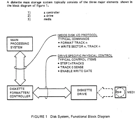
A diskette mass storage system typically consists of the three major elements shown in the block diagram of figure 1.
1) a controller 2) a drive
3) media
DISKETTE FORMATTER! CONTROLLER
IMOOS DISK I/O PROTOCOL TYPICAL COMMANDS • FORMAT TRACK n
• WRITE SECTOR n, TRACK n
DRIVE·SPECIFIC PHYSICAL CONTROL TYPICAL CON1RO L ITEMS
• STEP±nTRACKS • TRACK 0 SENSE • ENABLE WRITE GATE
DISKETTE DRIVE
,,'\..
--,
,.,.-
...(" I
bo \
MEDIA, '\ I
'or-
_..J ,,-~FIGURE 1 Disk System, Functional Block Diagram
[image:11.612.83.522.309.699.2]DISKETTE SYSTEMS Components and Interface
2 - 1.1 CONTROLLER
The controller forms a bridge between the main processing system and the data storage mechanism. On the system end, it interfaces to the system bus structure and participates in the disk I/O protoc.ol of the operating system. On the level of this system node, communications take place in the abstract world of data structures. The operating system (0/5) is oblivious to the physical details of the diskette drive mechanism and the recording media. It knows only of files that consist of multiple blocks of bytes which are identified by track and sector numbers (of which more, below), and of commands that facilitate the movement of data blocks to and from storage within the disk system. Central to the purpose of any controller is its ability to transform the high level 0/5 commands into the appropriate sequences of discrete steps that conform to the specific control requirements of the individual drive mechanism. On the peripheral end, the controller interfaces to the more elementary world of the drive mechanism.
2 - 1.2 DRIVE
The diskette drive contains the various elec tro-mechanical components and their associa ted control circuitry which a) rotate the diskette medium with a constant velocity, b) lower the read/write head onto and raise it off the medium, c) propel the head carriage as.sembly radially across the diskette surface, and d) detect a variety of speciaJ conditions in which some of the moving parts within the drive may find themselves. Among the special conditions that are detected in a typical drive, are a) read/write head positioning over Track~OJ b) media hardware write protect interlock, c) diskette index hole passage past fixed point in drive, and the like.
Many of the activities within the drive mechanism are independent of one another and are controlled over dedicated lines. The on/off sequencing of these ac tivities (such as
drive motor on/off, head carriage stepping, head lowering and raising) is one of the three major tasks which the controller has to perform. The other two are a) FORMA Ting of the diskette and b) supervising the actual data transfer to and from the recording medium.
2 - 1.3 MEDIA
Data is stored on the surface of a circular sheet that consists of a mylar base coated with an oxide that has magnetic properties especially suited for saturation recording. This sheet is contained within a protective envelope called a cartridge. The inner surfaces of this cartridge are lined with low friction material that offer minimal resistance to the rotating sheet. The cartridge typically has three openings through which the disk may be accessed by a) the read/write head, b) the drive spindle, and c) the photosensor which dete.c ts the passage of the index hole on the disk. Optionally, a diskette cartridge may also have a lhardware write protect' notch. This serves a purpose similar to the knock-out tab on a tape cassette: Prevention of unin tentional erasure of recorded data.
DISKETTE SYSTEMS
./'
Components and Interface
Diskettes are sensitive to temperature and humidity variations and must be treated with great care. However, in routine- utilization under normal ambient conditions, diskettes have proven to be quite rugged. Since the recording head is in contact with the medium during record or playback, it is important that the recording surface be kept free of dust particles and contaminants of any kind. A diskette that is not mounted in a drive should always be replaced in its dust jacket to prevent such contamination. For similar reasons, the diskette should only be handled by its jacket; and under no circumstances should the recording surface (exposed by the read/write head access Slot) be touched.
2 -1.4 TRANSFER MECHANISM
Data is transferred serially between the controller and the diskette drive. It is formatted and encoded in the controller prior to transcription to the recording medium, and it is decoded and decomposed to byte rendition prior to input to the main processing system.
Actual data transfer between the main processing system and the disk system (drive plus controller) may be designed to occur in three distinct forms:
1 )
2)
3)
Programmed Transfer Interrupt Driven Transfer
Direct Memory Access (DMA) Transfer
PROGRAMMED DATA TRANSFER
In a system, in which data is moved to and from mass storage by a program that executes in the main CPU for the duration of an I/O transaction, data movement is said to occur via Programmed Transfer. The program that performs the data transfer may be considered p~rt and parcel of the diskette controller and often' takes the form of firmware which resides within the hardware bounds of the controller.
I/O transactions are commonly initiated by subroutine c~lIs from the 0/5 to this
controller firmware. The CPU of the main proce4sing system will continue to execute various segments of this firmware until completion of the disk I/O transaction. Thus, the CPU is not available for other tasks during periods of disk I/O activity. It is for reasons of this constraint that this form of mass storage data transfer is only found in single user, single task oriented systems.
INTERRUPT DRIVEN DATA TRANSFER
A diskette controller may be designed to make use of an existing interrupt structure in the main processing system. . Such a structure effectively segments central processing time into discrete apertures, each dedicated to the execution of a program segment that services the particular interrupt level that is currently 'on line'.
In a system of this sort, the 0/5. initiates a disk I/O transaction by setting up the data transfer parameters for the interrupt level which is occupied by the mass storage subsystem and subsequently issuing a particular disk I/O command to the controller. The controller then releases the system CPU and proceeds to implement the 0/5 command with the required sequence of control steps. During this time interval, the system CPU
is free to perforrn other tasks (such as attend to other users or tasks in a
DISKETTE SYSTEMS Formats and Encodation·
multi-user/task environment). The controller will not interrupt the CPU again until it is either ready to transfer data to/from main memory or it has encountered an irrecoverable error condition. (Note: At present, no IMSAJ controller uses this data tr ansf er me thod)
DMA DATA TRANSFER
If the main processing system has the capability for direct memory access, then the diskette controller may be designed to make use of this capability. DMA structures frequently also make use of the interrupt structure for purposes of transaction initialization. But it is in the nature of the actual data transfer that a' significant difference may be noted between a DMA-based system and either of the two discussed above.
In both the Programmed Transfer and the Interrupt Driven Transfer scheme, the system CPU is involved in the data transfer operation. Depending on serial data transfer rates between the controller and the drive, and whether the controller has its own intermediate data buffer, the system CPU may be required to dedicate its time to disk I/O data transfer operations for uninterruptible periods of considerable length. Such constraints can severely impact a system's capacity to service more than one user or to control ~eal ti~e processes.
A DMA structure aJleviates this congestion by freeing the system CPU from direct involvement in the actual data transfer process. At the time of data transfer, the diskette controller requests and obtains control over the main memory bus long enough to transfer a byte (cycle steaUng scheme), then immediately releases this bus to the main processing system. Though the system CPU will experience an overall slowdown in its program execution during times of disk I/O activity, it is never preempted from performing such program execution for extended periods of time.
2 - 2 FORMATS AND ENCODA TION
2 - 2.1 TRACKS AND SECTORS
~
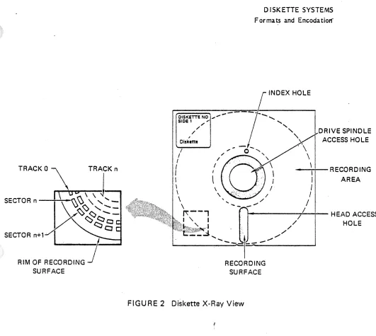
Unlike main memory RAM, in which each individual byte is uniquely identified by a singJe location within the system address space, a diskette mass storage system affords no such random access convenience on a byte level. Instead, data is st.ored bit-seriaJly in segments of 128 bytes (or multiples of 128 bytes). These segments are known as sectors. A number of sectors are concatenated to form one continuous ring concentric about the center of the diskette. Such a ring is called a track. The diskette contains a number of such recorded tracks, each adjacent to another, radiating outward from the innermost track nearest the diskette center to the outermost track nearest the periphery of the diskette (see Figure 2) •.
DSK -4
OISKETTENO , ... -SlOE 1 ,.
DISKETTE SYSTEMS Formats and Encodatiorf
/ ~ . / / Diskette DRIVE SPINDLE ACCESS HOLE
I I I
TRACK 0 \ TRACK n I I ---"-"'-RECORDING
1\
UD \ ,j
SECTOR n
I \ \ \ \ \ \ AREA
\
-
~~<'\."
<'\. V "" '-
" "-]X
''>~~o
~ " ' - - ... 1"f\--'
I~...-"",---,,-...;..--- HEAD ACCESS
SECTOR n+1·
I.
.
CJRIM OF RECORDING
1
SURFACE [image:15.612.38.569.44.519.2].: , ... ' .... ,.. .. I
...
-~ ......
-RECORDING SURFACE
FIGURE 2 Diskette
X-Ray
ViewData is stored and retrieved one sector at a time. This is accomplished by positioning the read/write head over the appropriate track, locating the specific sector within that track, and updating the data field of the sector with new data (write operation) or reading the data fi~ld of the sector into main memory (read operation).
The read/write head f3ass~s over a particular track once per revolution of the diskette. An arbitrary track start/stop reference is established by the detection of the passage of an index hole past a sensing mechanism. Sectors are numbered in ascending order (starting with Sector 1) from this index reference all the way around the track.
There are two distinct means of identifying successive sectors within a track. One makes use of sector holes which are equidistantly placed around the hub of the diskette in addition to the index hole; this is known as 'hard sec taring'. In this scheme each sector is identified by the number of sector holes that separate the sector from the start of the track (index). Such a diskette is shown in Figure 3 (Note: IMSAI does not make use of the hard sector technique).
DSK - 5
DISKETTE SYSTEMS
F or rna ts and E ncoda t ion
.,.,,-
.../
"
/10\
\ J
\
/
•
•
SECTOR 2 HOLE INDEX HOLE
SECTOR 1 HOLE
FIGU RE 3 Hard-Sector Formatting
The other method does away with these sector holes and employs identification fields that preface the data fields of the sectors; this is known as 'soft sectoring'. The identification fields contain track number and sector number information as well as synchronization patterns. This is the method qepicted in Figure 4. Before an operating system can access a diskette mass storage system and store data on a soft-sectored magnetic medium, the diskette must be prepared so that the aforementioned identification fields partition the tracks into individual sector areas and identify these as described; this is known as FORMA Ting the diskette.
to FISl.O
WR ITTEN TO Ol5K AT FORMAT TIMe
DISKETTE SYSTEMS Formats arid Encodatior("
FLOPPY DISkeTTE
FIGURE 4 Soft Sector Formatting
The length of the sector affects the maximum number of such sectors that may be placed on one track. Standard sector lengths are 128, 256 and 1024 bytes. Another factor that affects total number of sectors per track is the recording density. The recording density is a function of the data encodation and recording method used. This subjec t is treated in detail in the following subsec tirns.
2-2.2 DATA FORMATS
The particular organization of the data on a diskette is determined by the data formats that are used by the system. The format specifies the number of tracks on the diskette, the number of sectors on each track, the arrangement of synchronization and address mark patterns in the I D and data fields of each sector J the specific codes that
constitute those unique patterns, and the arrangement of information regarding track number, sector number and sector length code.
Some of the parameters regarding the specific format that is to be used on a particular drive at any particular time are maintained in a table located in the RAM memory of the controller. This table is loaded from the current settings of some hardware configuration options at the time of system initialization (following a reset condition). Some entries of this table may further be updated by one of the O/S utilities under user control; paramount among these is the selection of recording density. In the IMDOS O/S, the command file ST A T.COM serves this function. The user is referred to the technical reference sub-section on the particular controller for details regarding the function and usage of these parameters.
[image:17.617.140.523.57.436.2]DISK ETTE SYSTEMS· Formats and Encodation
A typical sector format is shown in Figure S. Each track COnter
immediately following the index reference. This index reference
rna.ln~
one GAP1physical index pulse from the drive (as is the case in mini-diskette forn-/ be only the also include an encoded index field which is separated from the physical i a.ts), or it may gap of type GAP4A (as is the case in standard diskette formats).
SellQ~x
pulse by a GAP1 and is separated from the next following sector (Sector 2) by aGA~tor
1 follows the gap which separates the last sector from the beginning of the track (i 3, Except for sectors are separated from adjacent sectors by a GAP3. Within each s'e, GAP4), all major information fields (ID and DATA) are separated by a GAP2. eCtor, the twoPHYSICAL INDEX PULSE
JL---_ - - - S - E - C O - T - R - " - - - . - - - S - E C T O R 11+1 END OF
I
----~ LAST SECTOR
10 FIELD DATA FIELD
r·
"I
I
_____
~I
I I I
1((
I
I
[=~~~..
_ GAP4....J GAf'4A INDEX GAP' SYNCII AM 110 CAC GAP SYNCIi AM20ATA CRe GAP3 SYNCH AM' 10 DATA en
rr---~ OATA D A T A ' ' " •• L - l - ___ _
I
"At G'"NOT PRESENT INTRA·SECTOR GP INTER·SECTOR GAP
ON MINI·DISKETTE
FI GU R E 5 Typical Track Data Organization
The ID-field of a sector begins with a bit-synchronization sequence Of
Next comes the I D-field address mark (AM). This is followed by severa f)1J1I bytes. informa tion regarding track
#,
sector# and a code which specifies sector Ie I bYtes of I D also include information regarding diskette side selec tion (for future sYst&th. It may to incorporate double sided diskette drives). The two cyclical redUndancyefll expansion bytes complete the I D-field. These CRC bytes are the result of aCh~ck
(C RC) rTlathema ticalDSK - 8
•
DISKETTE SYSTEMS,!,
FormatS and Encodation
procedure which introduces an evenly distributed redundancy over the information field. It is ·by means of this information redundancy that a majority of possible errors are intercepted during read operations. Conversely, if no error is encountered by this error detection scheme, then data integrity may be assumed with a high degree of certainty.
The data field also begins with a bit~synchronization $equence of null by tes, followed by the data field address mark. The maiilbody of data comes next, with the two CRe byte.s for the data field bringing up the rear.
2 - 2.3 DATA ENCODATION
Information is recorded on the magnetic surface of a diskette in the form of magnetic:; flux reversals that are induced by magnetic:; field reversals in the read/write head during a write operation. During a read operation, the recorded flux reversals induce electrical impulses in that same read/write head.
The significance of these flux reversals and their representative impulses is a function of the bit-serial data encodation process which the byte-parallel data. undergoes in the disk controller prior to recording on the diskette.
During a read operation, the serial pulse stream undergoes a complementary decoding process in which the data is once again rendered in byte form. It is the unique physical characteristics of the magnetic recording process that dictate the preferr~d encodation of binary information.
2 - 2.4 BIT CELLS
The simplest representation of serial binary data is in the form known as Non-Return to Zero· (NRZ). Figure 6 shows a series of ONEs and ZE ROs in NRZ. In this waveform, only the boundary condition that separates a ONE from a ZERO or vice versa produces a logical level change. Contiguous ONEs or ZEROs result in the extension over .Ionger periods of time of the samd logical level. In such bit sequences, the boundaries that delimit each bit-cell become imaginary and can only be inferred from the duration of a particular logical level (dashed lines in Figure 6).
,
The magnetic field reversals are coincident with reversals in logical level of the waveform that drives the write circuitry of the diskette drive. If serial data is presented to this circuitry in NRZ from, then the only flux reversals that would be recorded are those that represent logic level changes in the NRZ waveform. Sequences of contiguous ONEs or ZE ROs would, therefore, contain no information regarding bit-cell boundaries. This is a major weakness of NRZ data recording on magnetic media.
DISKETTE SYSTEMS
Forma ts and E ncoda tion
--{ r-
ONE BIT DURATIONDATA BIT ·CE LLS ..:.,0
J...I
~...:0:...L-I ~1
..J..1...:;0:....J-,1 ... 1-L1...;1--l1'-~01_0...,.J1'--0
..l..1_
1-JI_o--,-1
_1..;..L,1_1~1
_1 -,-0--,-1 _1 ... O--'-_0...a.-..-"-_NRZ WAVEFORM
*
*
*
*
*
•
•
•
*
* :::
FLUX REVERSAL • ::: NO REVERSAL'FIGURE 6 Bit·Cells and Flux Reversals .,'
DATA BIT CELLS
0
110
I
1I
0I
1 1101 0 10
I
1 0I
1 1I
10
I
1I
0 101
1I
1 FM WAVEFORMFM PU LSE TRAI N FLUX FIELDS IN MEDIUM
~
.
* •
I I I I II I I I I
* :::
PHASE REVERSAL IN CENTER OF BIT·CELL (ONE·BIT) • ::: NO PHASE REVERSAL (ZERO·BIT)FIGURE 7 FM Data Encodation
[image:20.637.34.588.41.763.2]FM ENCODA TION
DISKETIE' SYSTEM~
Formats and Encodation
The introduction of logic level transitions to signify bit-cell boundaries, and the adoption of the convention that the presence of a transition in the center of a bit-cell represents a ONE, while the absense of such a transition represents a ZE RO, produces the data encodation method known as Frequency Modulation or FM. Figure 7 shows an equivalent FM representation of the bit sequence shown in NRZ form in Figure 6.
The recording mechanism will induce magnetic flux reversals for every logic level change in this FM waveform. As a result, each bit cell will be bounded by flux reversals, 'regardless of whether adjacent cells contain alternating ONEs and ZEROs or contiguous ONEs or ZE ROs. This method is called FM because the resultant waveform contains two basic frequencies that are defined by the data rate and whose presence or absence is a function of the binary values of the bit stream that is encoded in this fashion. Each ONE bit cell is encoded by a complete cycle of Fl. Fl is also the datcl' rate. Each ZERO bit is encoded as one-half cycle of F2. The frequency of Fl is twice that of F2.
At the interface between the controller and the diskette drive, the FM encoded information is interchanged in the form of a pulse train rather than the FM waveform. T his pulse train is also shown in Figure 7. Note that the frequency of flux reversals is 2
XF1.
The rules for FM encodation of serial binary data are, therefore:
1) Write data pulses in the center of ONE bit-cells 2) Write clock pulses at all bit-cell boundaries
FMdata encodation has been known as Single Density recording since the advent of a Modified Frequency Modulation encodation technique which effectively doubles the amount of data that may be stored on any given stretch of magnetic medium at a specified velocity of linear travel. This technique is explained in the following section.
MFM ENCODATION
~
The FM recording technique is inefficient in that it requires two flux reversals for every ONE bit-cell. One of these is the actual reversal that specifies the logical value of the bit-cell (i.e. the flux reversal in the center of the bit-cell), the other forms the cell boundary with the next cell and provides bit synchronization clocking information.
If some of these clock pulses could be deleted at strategic locations in the bit stream where the characteristics of the surrounding data environment are sufficient to maintain bit synchronization, then the frequency of magnetic flux reversals would be lowered without undue degradation of recorded data integrity. Similarly, the recording frequency might then be increased until the frequency of magnetic flux reversals is, once again, that of the earlier FM process. This, in essence, is what is accomplished with the Modified FM (MFM) technique.
The rules for MFM encoding of serial binary data may be stated thus:
1) Write data pulses in the center of ONE bit-cells 2) Write clock pulses at the leading cell boundary if
DISKETTE SYSTEMS
Formats and Encodation
a) the previous cell was a ZE RO, and b) the current cell is a ZE RO
.f'
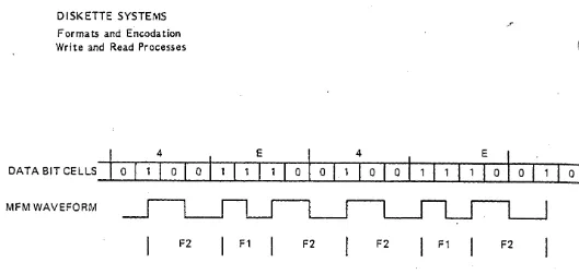
In MFM, the maximum frequency of flux reversal is equal to the data rate, while the Fl component is one-half of the data rate. Consequently, for any given rotational velocity of a diskette, twice as much data may be recorded in MFM on any given stretch of magnetic medium than is possible in FM. F.or this reason, the MFM encodation technique is also known as Double Density recording. Figure 8 shows the same serial data encoded in MFM. Note that this encoding scheme produces three baSIC frequency components, Fl, F2 & F3, whose relationship may be expressed as follows: Fl=2xF3;
F 2=1. 5xF3.
DATA BIT-CELLS
MFM WAVEFORM
MFM PULSE TRAIN
FLUX FIELDS IN MEDIUM
01 0
--.J
~F3
0
I
111
I
0 0I
0I
0n n
-I
FIGURE 8 MFM Data Encodation
2 - 2.5 SYNCHRONIZATION
0
o
I
0Ln
r
Fl--1
During a read operation, the read/write head is positioned over the track that contains the desired sector of data. The head mayor may not already be in contact with the recording surface of the diskette by the time it arrives at the destination track; in any event, the head will begin to pick up magnetic impulses from this track starting at some arbitrary and random location within the track.
The controller receives these pulses in electrical form and must make desisions regarding
DSK - 12
((l
DISK ETTE SYSTEMS Formats and Encodation .,1'.
their significance in terms of phase and frequency relationships, clock and data pulse separation, and, on a higher level, in terms of synchronization sequences that permit it to identify the start and stop of the I D and DATA fields within each sector over which the head passes.
FM SYNCHRONIZATION
In FM encoded tracks,. the various intra- and inter-sector gaps contain contiguous ONE-bits (but note exceptions, below). This constitutes a pulse stream at the Fl frequency. When traversing such a sequenc;;e, the controller mayor may not be in bit synchronization and thus may not be certain with regard to the identity of clock and data pulses in this stream. The bit synchronization circuitry of the controller searches for a sequence of ZE RO-bits in order to orient itself with respect to clock and data pulses. Once it has encountered such a sequence, it searches for an· I D address mark. In FM, this is a hex value of FE that differs from an ordinary data value of FE in that it is not encoded according to the standard FM en coda tion rules: some of its clock pulses have intentionally been deleted during the FORMA Ting of the diskette. Figure 9 shows the pattern for this address mark.
(It should be noted here that the MD lOuses ZE RO-bits in gaps of the types GAP1,3 and 4, but uses ONE-bits in GAP2 and the trailing byte of the data field. The FIF employs ZERO-bits in all GAPs)
F
01
DATA BIT-CELLS
PULSE TRAIN
t ___
t ___ t ___
MISSING CLOCKSFIGU RE 9 FM Address Mark
.D ISKETTE SYSTEMS
Formats and Encodation_
The recognition of this address mark signals to the controller that the succeeding bytes contain sector identification information. These bytes, in turn, are followed by the C RC bytes. A similar sequence of events takes place as the data field of the sector is traversed by the head.
During the data field update sequence in a sector write operation, the initial activation of the write current may glitch the magnetic medium in the region of GAP2. The exact location of this glitch varies from machine to machine, and may even vary from one write operation to the next. It is a function of a number of variables, primarily diskette drive speed variations. It may be stated that the purpose of GAP2 is to accommodate the aggregate dynamic range of these variables.
The spurious magnetic flux transition(s) which such a glitch may impart to the medium, can give rise to erroneous electrical pulses during playback. These, in turn, can derail the bit-synchronization which the controller had obtained while traversing the J D-field. It is ·for these reasons that the data field, too, starts with a bit-synchronization sequence of contiguous ZE ROs. ,
At the conclusion of a write operation, the write current is'turned off. As is the case with write current turn-on, turning it off may also induce spurious flux reversals in the recording medium. To ensure that this transient condition does not impact the trailing bits of the last data CRe byte, this turn-off is postponed until at least one byte after the last CRC byte.
Some controllers are designed to skip GAP2 during a read operation by counting off a fixed number of bytes and subsequently going into bit synchronization acquisition mode as the head enters the synchronization sequence of the data field. Others may rely on the fact that all Address Marks (AMs) are preceded by a certain number of ZERO-bytes and thus will not recognize an AM that is preceded by ONE-bits. In each case, however, the primary intent is the p~evention of erroneous AM recognition. Similarly, the imposition of the criterion, that an AM must be preceded by a sequence of ZE RO-bytes, also has the effec t of reducing the frequency of false I D AM detection during sector search for both write and read operations. Whether o'r not a controller makes use of all the synchronization features of the recording format is a function of its implementation.
MFM SYNCHRONIZATION
MFM synchronization is not very different from that of FM. One of the adverse side effects incurred by going from FM to MFM is the considerable loss of clocking information on the recorded track. It will be remembered that the increase in data capacity per unit distance on a track was obtained at the cost of clock pulses. This imposes the requirement for tighter synchronization acquisition criteria in MFM.
The bit-synchronization sequence is still a sequence of ZE ROs, only now there are more of them (typically twice as many as in FM). But it is in the Address Mark detection that the major difference is to be found. Whereas a single byte of FEH with modified clock pattern suffices in FM, the Address Mark for MFM encoded data consists of four
DISKETTE SYSTEMS
•• 1"'
Forma ts and Encoda tion
bytes of which the first three are unique datal clock pulse patterns and the fourth byte is the actual Address Mark value with normal MFM encodation. Figure 10 shows the pulse train for the MFM I D Address Mark. The first three bytes are A 1 H. with a missing clock pulse as shown. This missing clock pulse is chosen such that the basic frequency contents of these patterns conforms with the Fl, F2 & F3 components of conventionally MFM encoded data.
A
DATA BIT CELLS
I
0I
o
0 0 0PULSE TRAIN
rzzrmm
A1 A1 A1
FB, Fa
FIGURE 10 MFM Address Mark.
Contiguous sequences of ONEs are indistinguishable from contiguous sequences of ZE ROs encoded in MF M, except at boundary regions tha t separate two such sequences. It is for this reason that gaps are not filled wi th FF H sequences (as is the case in FM) 1
but with sequences of another hex code which produces alternating groups of pulses at F 1 and at F2, which, in turn, form an unbroken sequence of whole F1 and F2 lambdas (wavelengths)_ This code is 4E H, and the lambda sequence it genera te~ is [ •• F1,F2,F2,F1,F2,F2 ••• ], shown in Figure 11. Such a sequence is characterized by symmetrical 'peak shifting' during playback, and it aids in frequency tracking of the playback signal. It also makes possible the discernment of I D-field and data field synch sequences from GAP sequences.
DISKETTE SYSTEMS
Forma ts and Encoda tion Write and Read Processes
4
DATA BIT CELLS 0 0
MFM WAVEFORM
---1
I
F20
FIGURE 11
E 4 E
1 0 0 0 0 0
ILJ
ILJ
F1 F2 F2 F1 F2
MFM Inter- and Intra-Sector Gap Pattern
As is the case with FM, the turn-on and turn-:off of the write current during write opera tions may induce erroneous AMs in GAP2 and GAP3 (i.e. preceding and following the data field). To disallow erroneous AM detection on subsequent sector s~arch
operations, a controller may enforce the requirement that the AM be preceded by ZE RO-bytes. Since glitch-induced AMs will be embedded in 4E H sequences, they are readily recognized (and therefore ignored) as imposters. A further constraint is imposed by the requirement that three consecutive A 1 H AM bytes be preceded by these ZERO-bytes and followed by a normally ,\ttFM encoded FEH byte.
During a read operation, controllers may follow either of the two procedures already pointed out in the discussion on FM, above, to circumvent fallacious recognition of A,'."s in the vicinity of da ta fields.
The combined effect of all these constraints imposed upon the synchronization acquisition and retention process is the preve~tion of false synch acquisition and, in consequence of this, optimized data integrity and' system reliability.
2 - 3 WRITE AND READ PROCESSES
0
The discussion in the previous sections proceeded from the level of diskette system components down into the intricacies of patterns governing the magnetic encoding process. In the sections that follow, the higher level system interactions between a typical main processing system and the attached diskette system are discussed in terms of processes and the protocol that determines the particular form of their dynamic. Similarly, the sequences of operations that take place within the controller during typical
read and write transactions are also presented in detail. Throughout this discussion, access conventions which characterize the diskette I/O protocol of IN\SA I's IMDOS O/S serve as an example.
2 - 3.1 ACCESS CONVENTIONS
Regardless of the data transfer mechanism that is employed in a disk system (be it programmed, interrupt driven, or DMA data transfer), the disk I/O protocol usually
DSK - 16
(
[image:26.646.69.598.42.293.2]DISKETTE SYSTEM .. r Write and Read Processes
consists of these major components: Command Parameters Set Up, Disk System Call-Up, Command Execution (1; Sector Search, 2: Data Transfer), and Status Reporting. The particular mechanics of command, data, and status transfer between main system and disk system is dictated by the data transfer mechanism, however. Thus, in a DMA organization, the command parameters must be set up somewhere in system RAM out of which it is executed by the disk controller subsequent to a command call from the main system. In a programmed data transfer environment, these same command parameters might be forwarded to the data transfer firmware module via the system stack and/or some of the CPU registers.
The primary items that must be specified in any disk I/O transaction are a) type of operation (read or write, format, whatever), b) site of origin of data block to be moved elsewhere (RAM area, in the case of a write operation; drive/track/sector, in the case of a read operation), c) site of destination of data block to be moved, and d) special considerations (FM or 1\1FM, sector length).
The disk I/O protocol specifies the format of the data which conveys' this information; it also specifies the sequence in which the entire disk I/O transaction transpires.
I n the discussion that follows, the basic structure of a typical disk access protocol and its associated formats is presented first, and then the typical sequence for a write and a read operation is detailed.
BYTE COMMANDS AND COMMAND ST RINGS
Disk access commands may be categorized into the two classes of Set Up Commands and I/O Commands. The former are executed to set up certain variables (write protect, write enable any drive; restore to track 00 any drive; modify Command String Address Array) and are called Byte Commands. The latter are executed to perform the actual data transfer to and from the disk system; these usuany involve a number of parameters that are set up in system memory prior to the execution of what is known as a Command String.
The basic control element of any disk access is the byte code which is forwarded to the disk controller in the A-Register of the CPU during the execution of an instruction tha t accesses the controller. I n the case of the MD I 0 and the D I 0 controllers, the control byte is conveyed via the execution of a CALL instruction to the controller firmware. The FJF controlier, on the other hand, is accessed via the execution of an OUT instruction that addresses the FIF controller command port. For ease of discussion, all
subsequent references to the controller access mechanism presumes the use of a D 10 or an MOIO controller.
The control byte consists of two 4-bit fields that specify a) the type of command (upper nibble) and b) either the drive or drives specified for the opera tion (in the case of Byte Commands 2, 3 and 4), or the Command String Pointer (in the case of an I/O Command). Distinction bety,;een Byte Command versus I/O Command is made by setting the upper nibble to ZE RO for an I/O Command.
DISKETIE SYSTEMS
. Wrhe and Read Process-es
ACCESS SCHEMA
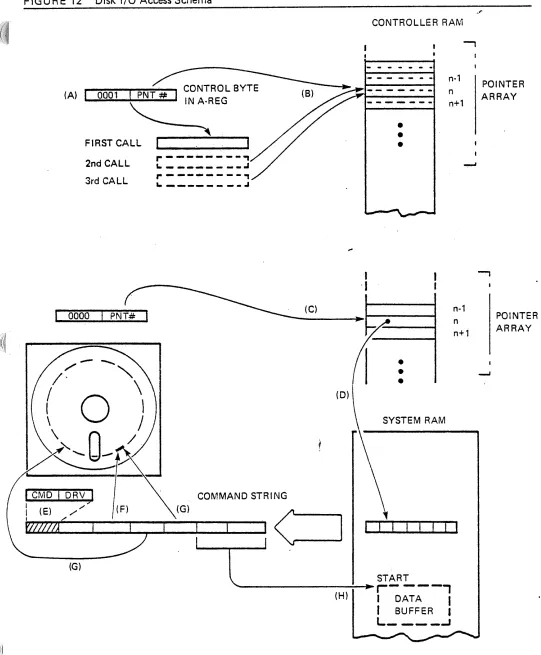
The Interrelationship of the Control Byte, Byte Command, String Pointer, and Command String within the environment of system main memory and diskette may be visualized as shown in Figure 12. The following paragraphs describe this interrelationship. The
letters in brackets refer to the appropriate region within Figure 12.
DSK - 18
FIGURE 12 Disk I/O Access Schema
CONTROLLER RAM
(A) 0001 I . CONTRO.LBYTE
--~--~~-.----~
INA·REGFIRST CALL ... 1 ... _ ... _ _ --"
2nd CALL 3rd CALL
r--- ... ----.,
L. _ _ _ _ _ _ _ _ -' ,.---~I. _ _ _ _ _ _ _ _ .I
I
-I
•
•
•
0000 (C)
•
•
•
0
(D) SYSTEM RAMCOMMAND STRING
l
START---~
•• r- - - - ,
(H) I DATA
I
I
BUFFER I(G)
L _ _ _ _
..JDSK - 19
n-1 n n+1
POINTER ARRAY
-,
POINTER ARRAY
--'
"'I
[image:29.612.21.562.58.713.2]·OISKETIE SYSTEMS - Write and Read Processes
The Control Byte specifies either Byte Command or Command String execution [A]. Byte Command 1 is used to modify the contents of the Command String Address Array [B]. Command String execution is initiated by conveying the proper Control Byte in the A-Register via a CAL L to the controller [C]. The controller uses the pointer to locate the start of the Command String residing somewhere in system RAM
[0].
The first byte in this Command String identifies the type of command that is to be executed (Write Sector, Read Sector, Format Track, Verify Sector, Write Deleted Sector Mark) and the drive on which this action is to be performed [E]. The third byte specifies .sector length, track number extension (0-255 or 256-511) and side selecti,?" (possible future expansion to double sided media)[F].
The fourth byte specifies the track, the fifth byte the sector that is involved in the transaction [G]. Bytes six and seven specify the start of the area in system main memory into or out of which data' will be moved from or to the specified sector on the diskette [H]. Byte two is reserved for forwarding of the end-of-transaction status from controller to system.All Command Strings require at least four bytes to specify the minimum set of parameters. The maximum number of parame ter bytes that may compose a command string is seven. The complete Command String must be set up prior to the execution of the CA~ L to the controller. Variables tha,t are controlled by Byte Commands, may be modified by these commands at any time between the execution of Command Strings.
W R ITE/ READ SE QUE NCES
First, the Command String has to be set up properly, and the Command String Address Array must reflect the starting location of this new Command String. Anyone of the sixteen possible pointers may be used. Usually, the array is set up once early in the system initialization phase immediately following power-on, and individual pointer values are modified only rarely thereafter. That segment of the O/S which is responsible for disk 110, has to make sure that the Command String is set up in alignment with the current value of whichever pointer it will specify during its CAL L to the disk controller.
The Command String is composed according t~ the format already indicated in the previous section (ACCESS SCHEMA). Whether or not Command String bytes five through seven need to be set up depends on the type of command that is to be executed. Next, the Control Code is placed in the A-Register and the system executes a CALL instruction to a specified location within the disk controller firmware. This firmware examines the contents of the A-Register. If it detects a hex-ZE RO value in the upper nibble, it interprets the lower nibble as a pointer number for the Command String Address Array. It looks up the 16-bit address value stored in the array location(s} specified by this pointer and uses this address to locate the start of the current Command String.
The Command String contains all the necessary parameters needed by the disk controller to perform a disk I/O transaction. The first byte in this string identifies the Command String as either a write or a read operation, as well as the drive that is to be involved.
OSK - 20
')
•
WRITE OPERATION
DISKETTE SYSTEMS Write aa:ad Read Processes
The controller issues a control sequence to the diskette drive which instructs this drive to
1) move the read/write head 'N' steps
+/-
from current location 23
) lower the head onto the medium (if not already lowered) ) perform a read operation
The controller then examines the pulse stream coming in from the drive and a,cquires bit-and sector-synchronization (as described in earlier section on SYNCHRON IZA TION).
After it has' verified that the read/write head has successfully traversed the I D field of the sought after sector (Address. Mark check OK, CRC computation OK) and is entering the intra-sector gap (GAP2), it counts .off a specified number of bytes and turns on the write current.
The controller then proceeds to write the bit-synchronization sequence for the data field, the Address Mark, the data-fieJd itself, followed ,by the CRe bytes and the end-of-record byte. Once this is done, the controller orders the write current to be turned off.
If the transaction was accomplished without indication of any error, the controner places a 01 value in byte two of the Command String to indicate an 'allis weill status.
This code is also placed in the A-Register before the controller firmware completes its business by returning to the CAL Ler.
If an error indication was noted by the controller, then it will either forward an appropriate error code to the system, or it will repeat the execution of the Command String a specified number of times before giving up and indicating the requisite status to the system. The controller's response to error conditions. varies with the error type encountered and is treated in another section, below (E RROR HAND LING).
The controller will perform a somewhat differenl sequence of
operation~
when it is informed to FORMAT a track. In this case, the controller instructs the drive to position the read/ write head over the specified ·track and lower the head. The controller next awaits the index pulse from the drive electronics which signals start of track. It then lays sector ID-fields and dummy DATA-fields from start to end of track in the format specified by the third byte in the Command String that is currently being - executed.READ OPERATION
The read operation differs only slightly from the write operation. The sequence that results in the positioning of the read/write head over the desired track and the identification of the proper sector within that track is the same as the one that is used in a writ~ operation. After traversal of GAP2, the controller looks out for the bit-synchronization sequence and then the data field address mark (AM). Identification of AM leads to the subsequent readback of the data field into the system RAM region specified by bytes six and seven of the current Command String. Status reporting takes place as in a write operation.
DISKETTE SYSTEMS'
Write and Read Processes
2- 3.3 ERROR HANDLING
Error handling may be either in the simple form of reporting each encountered malfunction immediately back to the system, or in the form of a ,sophisticated error recovery procedure within the disk controller itself. The latter implementation relieves the main processing system of much -of the housekeeping task that is involved in the handling of errors.
The controller may be equipped with enough intelligence (i.e. necessary firmware routines) to make a determination regarding the nature of the anomaly encountered during a disk 1/0 operation and to respond accordingly. There are several error classes, and from some of these the controller may recover on its own initiative. Some of these conditions are outlined below.
I n all of the cases where a transaction reaches a point where a CRC error is discovered by the controller, the latter may be permitted to perform a number of 'retries'. During a retry, the controller executes the current Command String all over again. This procedure is based on the statistical fact that a majority of such errors are 'soft' errors which have a low but finite probability of occuring every time data is recovered from a magnetic medium. Inability to come up with an error-free data recovery after a specified number of retries produces the inference that there
is
something seriously wrong with the magnetic medium in the region occupied by the sector in question. In such cases, the controller will discontinue retries and report a 'hard' error to the system.Another type of error from which the controller may recover on its own, is the case where track information in the sector I D-field does not match the specified target track number. In this case, the controller may be allowed to reposition th~ read/write head several times in an attempt to achieve a track number match; the assumption being that the head carriage control mechanism fails, on occasion, to correctly position the head as instructed.
The remaining error types may be grouped into ~the three classes a) Command String Error, b) Recoverable System Error, and c) Hardware Error. The last class includes the -previously described error conditions when these could not be corrected through retries by the controller. Command String Errors are usually the result of format errors in the Command String (track number too large, illegal command number, etc). Recoverable System Errors are those errors that may be corrected by altering a variable which currently disables an operation as specified by the Command String (hardware or software write protected diskette, drive not ready).
-DSK ;':22
IMSAI DISKETTE SYSTEM
. .r
General
Configuration
3 IMSAJ DISKETTE SYSTEMS
3 -1 GENERAL
The 'IMSA I family of disk systems offers the user a wide variety of system configurations. Both standard and mini drive systems are available in several hardware arrangements ranging from simple expansion drive units with or without controller, to fully integrated computing systems •. Drives may be combined with different types of controllers to form the desired configuration. Arnong these controllers is available a broad range of features, including single and double density recording for both mini and standard drives, capability for attachment of additional drives, and the incorporation of several controllers within one computer mainframe. IMSAJ's powerful IMDOS multi-disk operating system supports all of these system configurations.
3 - 2 CONFIGURATIONS
3 - 2.1 CONTROLLERS
The variety of disk system configurations is made possible by the flexibility of IMSA I disk controllers. These are the FIF, the MOIO, and the 010. Of the latter, several models provide multiple single and double density formats. The major features of these controllers are outlined below. Detailed descriptions of their operational characteristics may be found in the reference sections that follow this common front-end text.
FIF CONTROLLER
The Floppy Interface consists of two S100 Bus printed circuit boards, the InterFace Master (IFM) and the Floppy Interface Board (FIB). It uses a data format that is fully compatible with the IBM 3740 format. The FIF attaches to a total of four standard diskette drives and supports single density recording (FM} only. The IFM contains a OMA-based data transfer mechanism that is organized around an internal 8080 microprocessor. The firmware program is contained in two (2) onboard 1 K ROMs.
MOIO CONTROLLER
The MD lOis a single board diskette controller designed around an LS I floppy controller integrated circuit (1771). It attaches to a total of four mini-diskette drives and supports a single density format that is similar to the IBM 3740 format. The MD 10
employs a Programmed Data Transfer mechanism and contains the diskette
format/control firmware in an onboard 2K ROM/EPROM.
010 CONTROLLER
The 0 lOis a two board controller consisting of a Disk I/O and a Programmable Data Separator printed circuit board. The D 10 attaches to a total of four standard diskette drives and/or three (or four, depending on version) mini diskette drives, and supports both single and double density recording formats. The 010 comes in four versions, each with some unique features that are not available in the other versions.
IMSAI DISKETTE SYSTEM
Configuration
The DIO-A is the original version and supports the two early IMSA I data formats: Format I, the IBM 3740 compatible single density format, and Format V, a 128 bytes/sector double density format. 0 IO-A uses Format I for both standard and mini drives, Format V for standard drives only.
010-8 is a variant of DIO-A which differs from the latter only in that it incorporates a different step rate for standard drives to provide compatibility with the CalComp 142.
NOTE: Both the DIO-A and B models have been replaced by the DIO-C.
DIO-C supports the new single and double density formats and is designed to interface exclusively with standard drives. In addition to being backward compatible with the earlier Format I (though not V), it also communicates in Formats II, III and IV.
D IO-D also supports the new formats and is designed to interface exclusively with mini drives. Up to four mini diskette drives may be attached to a 010-0.
3 - 2.2 HARDW ARE COMPATIBI L ITIES
Though- a variety of diskette drives, both mini and standard, may be attached to IMSAJ diskette formatter! controllers, the range of permissible controller! drive configurations is delimited by both hardware and format compatibility constraints that arise from the specific characteristics of these system components. The matrix shown in Figure 13
indica tes hardware compatibilities among the IMSA I controllers and diskette drives of
sever al manufactur ers.
CONTROLLER DATA TRANSFER MODE
~
F1F DMA
~
MOIO PROG
."
DIO-C PROG
"
010-0 PROG
LEGENDS:
IMSAI DISKETTE SYSTEM
Configuratio'~
FIGURE 13 Controller/Drive Compatibilities
STD MIN
DRIVE PERSCI CALCOMP SHUG MPI MICROP
TYPE 277 142 400 851 1015
STD X
MIN X X
.,.
~sro X X
~
MIN X X
MUTUALLY EXCLUSIVE DR IVE TYPES
STEP RATE JUMPER·SELECTABLE ( 12ms FOR MPI, 40ms FOR SHUG. ) IF JUMPEREO FOR SHUG 400, MOIO WILL SUPPORT MIX OF SHUG &
MPI, BOTH 35 TRACKS
DRIVE TYPE SWITCH SELECTAStE MPI STEP RATE IS 5ms
~ USE WITH MPU·A ONLY
JMSAI DISKETTE SYSTEM Configuration
3 - 2.3 FORMAT COMPATIBr L ITIES
. /
As was already Indica ted In the brief descriptions of I MSA I contr Oilers, above, thes e
controllers feature a range of data formats, not all of which are necessarily supported
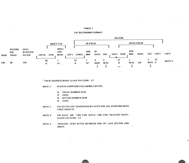
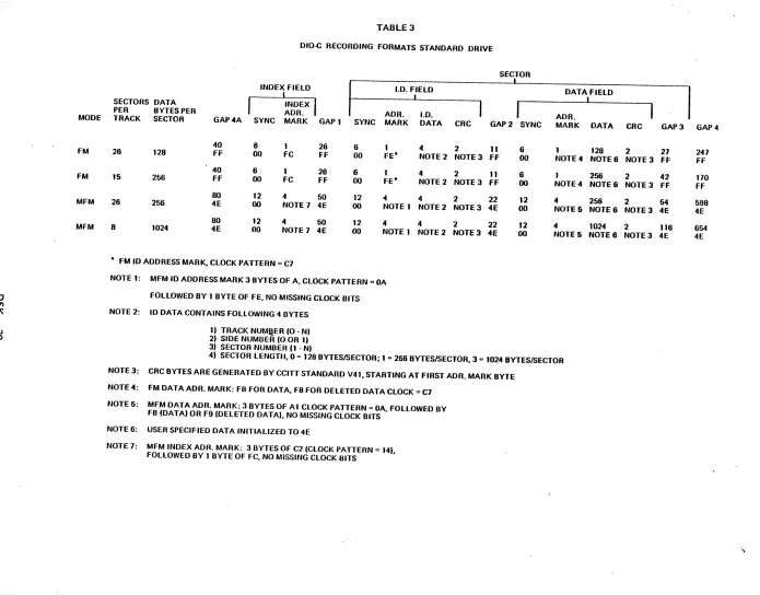
by each controller. Figure 14 shows a matrix in which format compatibilities are correlated with controller type and IMOOS versions. Note that IMOOS 2.05 (or later revision) supports all data formats used by OIO-C & 010-0. Tables 1 through 4 show the field organization of the recording formats as they are utilized by the different
controllers.
F or details regarding media conversion techniques involving flies created in systems utilizing OIO-A or 010-8 and to be transferred to systems utilizing OIO-C or 010-0,
the user is referred to the IMDOS User's Manual •
.
CONTROLLER
FtF
MolO
OIO·C
010·0
IMSAI DISKETTE SYSTEM
Configura
ti~n
FIGURE 14 Format Compatibilities
FORMATS SUPPORTED BY IMoOS VERSION
I-« DRive TYPE RECORD NOTES
~ DENSITY
a::
2.02 2.05 0 14- STO MIN
I I I 128/26 128118 SO IBM 3140 SO FORMAT. IMSAI DEFAULT I I II II 256/15 256/9 so 2nd IBM 3740 SO FORMAT
I 1.1I.III,IV III 256/26 256/17 DO IBM 00 FORMAT 1. IMSAI DO DEFAULT I 1.II,IiI.IV IV 1024/8 1024/5 00 IBM 00 FORMAT 2
[image:37.612.62.573.28.488.2]o
Vl
A tv
OCt
SECTORS OAT A PER BYTES PER fvnDE TRACK SECroR
FM 26 128
INDEX FLO
--INDEX
I
ADRTABLE 1
Flf RECORDING FORMAT
I
10 FIELDADA. II)
SECTOR
DATA FIELD
Ann.
GAP4A SYNC MARK GAI'1 SYNC ..
I
MRK DATA CRC GAP 2 SYNC MBK. DATAI
•
I45 31
"
2 170 Fe 0 FE' NOTE N01E 0
1 2
• fM 10 ADDRESS MABK CLOCK PA1TERN--C7
NOTE 1:
NOTE 2:
NOTE 3:
NOTE 4:
ID DATA CONTAINS FOLLOWING <1 BYTES
1) TRACK NUMBEH (ONI 21 ZERO
31 SECTOR NUMBER (O-NI
41 ZERO
CRe BYTES ABE GENERATED BY CCITT STD V<11, STARTING WITH FIRST AM BYTE
FM DATA AM: FlUi FOR 'OATA', F8U FOB 'OELETED OATA', CLOCK PATTEBN' C7
TRAILING ZERO BYTES BETWEEN END OF LAST SECTon ANO INDEX
NOTE 120 ~
enc GAP 3 GAP 4
2 32
NOTE 0 NOTE 4
l
[image:38.792.120.727.57.581.2]o
Vl 7\ t-J \.0 MODE FM FM SECTORS PER TRACK 18 9MOIO RECORDING FORMAT
SECTOR
I
10 FIELD DATA FIELD
I
DATA BYTES
I
I
I
I
SYNCH PERSECTOR
128
256
ADR. 10 ADn.
GAP 1 SYNCH MARK DATA CRC GAP 2 MARK
12 2 4 2 11 6 1
00 00 Fe NOTE t NOTE 2 FF 00 NOTE 3
12 2 4 2 11 6 1
00 00 FE" NOTE 1 NOTE 2 f f 00 NOTE 3
• FM 10 ADDRESS MARK CLOCK PATTERN = C7
NOTE 1:
NOTE 2:
NOTE 3:
NOTE 4:
10 DATA CONTAINS FOLLOWING 4 BYTES
1l TRACK NUMBER (O·N)
2~ SIDE NUMBER (0 or 1)
3)
4)
SECTOR NUMBER (see also NOTE 4, bulow)
~_~Ton LENGTU: 0 = 128, 1 = 256
CRC BYTES ARE GtNERATED BY CelTT STD V41. STARTtNG WITH fiRST AM BYTE
fM DATA AM: FB FOR 'OATA', F8 fOR 'OELETED DATA', CLOCK PATTERN = C7
fOR PURPOSES OF SECTOR FORMAT RECOGNITION DURING SECTOR SEARCH BY 1771 LSI, ntis BYTE ALSO INCORPORATES SECTOR LENGTH SPECIFICATION:
MSB
I I
J LSB~---0:. 128 liYTE SECTOR 1 = 256 BYTE SECTOR
NOTE 5: TRAILING ZERO BYTES BETWEEN END Of LAST SECTon AND INDEX
DATA
128
256
I
CRC GAP3 GAP4
2 1 11 NOTE 6 NOTE 2 f f 00
2 1 11 NOTE 5 NOTE 2 Ff 00
o til
'"
I~ /
.
•
MODE FM FM MFM MFM [image:40.792.42.737.35.579.2]SECTORS DATA PER BYTES PER
TABLE 3
DIO-C RECORDING FORMATS STANDARD DRIVE
INDEX FIELD
I
INDEX
I
ADR.SECTOR
I
1.0. FJELD DATA FIELD
I I
TRACK SECTOR GAP4A SYNC MARK GAP 1 ADR. 1.0. ADR.
SYNC MARK DATA CRC GAP2 SYNC MARK DATA CRC GAP] GAP 4
40 6 1 26 6 1 4 2 11. 6
.,
128 2 2726 128 FF 00 FC FF 00 FE" NOTE 2 NOTE] .FF 00 NOTE 4 NOTE 6 NOTE] FF
40 6 1 26 6 1 4 2 11 6 1 256 2 42
15 256 FF 00 FC FF 00 FE" NOTE 2 NOTE] FF 00 NOTE 4 NOTE 6 NOTE] FF
80 12 4 50 12 4 4 2 22 12 4 256 2 64
26 256 4E 00 NOTE 7 4E 00 NOTE 1 NOTE 2 NOTE] 4E 00 NOTE 5 NOTE 6 NOTE 3 4E 80 12 4 50 12 4 4 2 22 12 4 1024 2 116 B 1024 4E 00 NOTE 7 4E 00 NOTE 1 NOTE 2 NOTE] 4E 00 NOTE5 NOTE6 NOTE] 4E " FM 10 ADDRESS MARK. CLOCK PATTERN = C7
NOTE 1: MFM ID ADDRESS MARK] BYTES OF A, CLOCK PATIERN =z OA
FOLLOWED BY 1 BYTE OF FE, NO MISSING CLOCK BITS
NOTE 2: ID DATA CONTAINS FOLLOWING 4 OYTES 1) TRACK NUMQ.ER (0 -N) 2) SIDE NUMOER (0 OR 1)
3) SECTOR NUMBER (1 -N)
4) SECTOR LENGTI-J, 0 = 128 BYTES/SECTOR; 1" 266 BYTES/SECTOR. 3'" 1024 BYTES/SECTOR
NOTE 3: CRC BYTES ARE GENERATED BY CelTT STANDARD V41. STARTING AT FIRST ADR. MARK BYTE
NOTE 4: FM DATA ADR. MARK: FB FOR DATA, F8 FOR DELETED DATA CLOCK = C7
NOTE 6: MFM DATA ADR. MARK: 3 BYTES OF Al CLOCK PATTERN = OA, FOLLOWED BY FB (DATA) OR F9 (DELETED DATA). NO MISSING CLOCK BITS
NOTE 6: USER SPECIFIED DATA INITIALIZED TO 4E
NOTE 7: MFM INDEX ADR. MARK: 3 BYTES OF C2 (CLOCK PATTEflN = 14). FOLLOWED BY 1 BYTE OF FC, NO MISSING CLOCK BITS