DOI 10.1007/s00158-017-1798-x
INDUSTRIAL APPLICATION
End-effector design optimisation and multi-robot motion
planning for handling compliant parts
Emile Glorieux1 ·Pasquale Franciosa2·Darek Ceglarek2
Received: 9 March 2017 / Revised: 23 August 2017 / Accepted: 24 August 2017 / Published online: 9 September 2017 © The Author(s) 2017. This article is an open access publication
Abstract The deformation of compliant parts during mate-rial handling is a critical issue that can significantly affect the productivity and the parts’ dimensional quality. There are multiple relevant aspects to consider when design-ing end-effectors to handle compliant parts, e.g. motion planning, holding force, part deformations, collisions, etc. This paper focuses on multi-robot material handling sys-tems where the end-effector designs influence the coordi-nation of the robots to prevent that these collide in the shared workspace. A multi-disciplinary methodology for end-effector design optimisation and multi-robot motion planning for material handling of compliant parts is pro-posed. The novelty is the co-adaptive optimisation of the end-effectors’ structure with the robot motion planning to obtain the highest productivity and to avoid excessive part deformations. Based on FEA, the dynamic deformations of the parts are modelled in order to consider these during the collision avoidance between the handled parts and obsta-cles. The proposed methodology is evaluated for a case study that considers the multi-robot material handling of sheet metal parts in a multi-stage tandem press line. The results show that a substantial improvement in productivity can be achieved (up to 1.9%). These also demonstrate the need and contribution of the proposed methodology.
Emile Glorieux [email protected]
1 Department of Engineering Science, University West,
S-461 86, Trollh¨attan, Sweden
2 Warwick Manufacturing Group, University of Warwick,
CV4 7AL Coventry, UK
Keywords End-effector design optimisation·Motion planning·Multi-robot systems·Material handling· Compliant parts
1 Introduction
Compliant sheet metal parts are widely used in manufactur-ing industries such as automotive, aerospace, and appliance. The compliance of the parts makes them deform during the robotic material handling in manufacturing systems. Con-trolling those deformations is necessary to maintain the dimensional quality. The magnitude of the part deforma-tions is influenced by robot motion planning parameters (i.e. transfer paths, trajectory velocities and accelerations) and design parameters (i.e. end-effector design). Hence, the effect of the part deformations can become a limitation for the productivity (Li and Ceglarek2002). In multi-robot systems, there is also the additional difficulty that several robots operate in close proximity. A typical example is the multi-robot material handling in multi-stage sheet metal press lines where the plates need to be transferred between the presses as quick as possible.
There are several issues that arise with multi-robot han-dling of compliant parts. A first issue is to tune the velocities and accelerations of the robots to avoid permanent plas-tic deformations of the parts during handling in order to maintain the dimensional quality and to avoid damaging the parts.
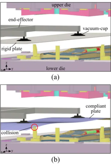
deformation can be over 150mm. Fig.1shows this for the press line example. When assuming that the part is rigid (Fig.1a), the collision between the deformed part and the lower die (Fig.1b) remains undetected.
A third issue is that even elastic part deformations during handling can affect the dimensional quality (Li et al.2002), for example due to position errors or part distortions, and cause large dimensional variations and/or parts that have to be scrapped. The larger the magnitude of the part deforma-tions, the higher the risk that this happens. In the sheet metal press line example, large elastic deformations increase nest-ing errors (Li et al.2002), which are positioning errors of the plate in the lower die when it is dropped by the end-effector. This causes dimensional variations when the plate is stamped. Another problem is the part distortions during die contact (Li et al. 2002), which occur when the end-effector drops a plate in the die and the contact force is unevenly distributed due to the deformations.
A fourth issue is that the design of the end-effectors not only affects the part deformations but also plays a crucial role in avoiding collisions between the robots (and other moving obstacles). The end-effectors are often the first to interfere with the other robot(s) in the case of a collision. Modifying the design of the end-effectors will affect to what extend the robots are able to operate simultaneously in the shared workspace. Hence, the end-effector designs
(b)
(a)
Fig. 1 Loading blank plate into press (a) rigid plate model,b compli-ant plate model (collision between plate and lower die indicated by red circle)
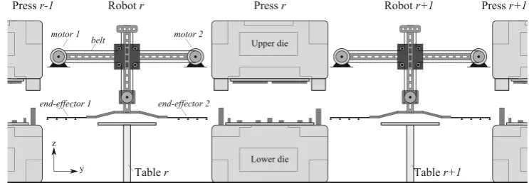
influence the multi-robot coordination and consequently the productivity. Figure 2 illustrates this for the sheet metal press line example, looking at how long the press needs to wait until the end-effector that loaded the unstamped has retracted (to the left) before the upper die of the press can move downwards to perform the stamping operation. It can be seen that the design of the end-effector influences the waiting time before starting the stamping operation by the press. The position of the robot is the same in both sce-narios, but the end-effector in Fig. 2a is larger compared to Fig.2b. It shows that the position of the press is higher in Fig.2a because it has to wait longer for the larger end-effector to retract from the shared workspace. This will result in a longer cycle-time compared to scenario with the smaller end-effector shown in Fig.2b.
Designing the end-effectors and planning multiple robot motions are thus twointer-dependentproblems that together determine the system’s productivity. The topic of this paper is how to co-adaptively optimise these two problems to account for this inter-dependency.
The contribution of this paper is the proposed multi-disciplinary methodology to simultaneously optimise the end-effectors’ design and the manipulation planning in multi-robot material handling systems to exploit the syn-ergies to improve the productivity. The novelty of the proposed methodology is that it integrates the end-effectors’
(a)
(b)
[image:2.595.77.262.405.678.2] [image:2.595.328.519.407.687.2]design problem with the main relevant aspects of robot motion planning. The methodology thereby co-adapts these aspects to each other in order to further improve the produc-tivity of the system. The industrial application is presented in a case study that considers the material handling in a real-world tandem sheet metal press line for multi-stage stamping.
The remainder of the paper is outlined as follows, Section2gives an overview of related research works, fol-lowed by Section3that presents the considered case study. Section 4 formulates the investigated problem and dis-cusses how it is modelled. Next, the proposed optimisation methodology is presented in detail in Section5. Section6 describes how the proposed methodology is implemented for the case study. The performed tests for the evaluation are presented in Section 7 and the results are discussed in Section 8. Finally, a summary and the conclusions are discussed in Section9.
2 Relevant works
Two categories of research are relevant for this paper, firstly research on design optimisation for material handling end-effectors, and secondly on robot motion planning for material handling.
In the first category, there are several previous research works in literature that investigate optimising the design of end-effectors for material handling (Mantriota and Messina 2011; Patel et al. 2013; Feng et al. 2013; Tuleja and Sidlovsk´a 2014; Schmalz et al. 2016; Datta et al. 2016). Patel et al. (2013) and Feng et al. (2013) propose actu-ated end-effectors for material handling, respectively with a linear axis and crossbar mechanism, in order to expedite material handling operations for sheet metal parts. Mantri-ota and Messina (2011) and Tuleja and Sidlovsk´a (2014) investigate how to calculate the maximum holding force for end-effectors with vacuum-cups. Schmalz et al. (2016) present an approach for automatically dimension grippers based on the properties of the handled objects, the handling environment, the handling device, and the motions for the handling process. Datta et al. (2016) investigate optimising the design of a 7-link gripper with piezoelectric actua-tion, whilst also optimising the performance of the actuator in the optimisation study. These previous research works are mainly focusing on handling rigid parts, or assume that compliant parts remain rigid during handling. Another issue is that these works typically consider the material handling operations isolated, and not as a part of a manu-facturing system. These works are thus not applicable for optimising the design of end-effectors for handling com-pliant parts, in systems where multiple robots operate in a shared workspace.
Though, Ceglarek et al. (2001) propose an end-effector design methodology for compliant sheet metal parts to min-imise the deformations during handling. This is extended later by Li et al. (2002) with a dexterous part-holding model to more accurately estimate the part deformations. Hoffmann and Kohnh¨auser (2002) also propose a generic methodology to calculate the ideal positioning of vacuum-cups for the end-effector to hold sheet metal parts, taking into account the dynamic behaviour of the part during handling. Although the part deformations are taken into account, each robotic material handling operation is still considered isolated, instead of being part of a manufacturing system, and thus neglect the environment.
For the second category, material handling motion plan-ning research typically consider a predefined end-effector design, and often also assumes that the handled parts are rigid, even though they are compliant. Pettersson et al. (2007) propose simultaneously optimising the robot motion planning and robot drive-train system parameters. A novel concept for robot installation, drive-train, and motion plan-ning for compact and fast press tending has been proposed by Platzer et al. (2013). Glorieux et al. (2016) propose a trajectory and coordination optimisation methodology for the motion planning of the material handling in multi-stage press lines, to improve the productivity. These previous works use a predefined end-effector design is used and the parts’ compliance is not considered. Li and Ceglarek (2002) investigate material handling of compliant sheet metal parts, focusing on time-optimal collision-free trajectory genera-tion whilst avoiding excessive part deformagenera-tions to maintain the dimensional quality of the parts. However, only a sin-gle isolated robot with static obstacles in the workspace is considered.
Table 1 gives an overview of the previous works. A broader survey of model-based manipulation planning of deformable objects is given by Jim´enez (2012). It can be concluded that there is currently no available methodology to optimally design end-effectors and motion planning for maximum productivity of material handling with compliant parts in multi-robot systems.
3 Case study
In order to illustrate the proposed methodology, it is applied to a specific real-world industrial case study that considers the multi-robot material handling system in a tandem sheet metal press line for multi-stage stamping. The motion plan-ning of these material handling systems is a critical issue for the industry (Glorieux et al.2015a).
Table 1 Overview of previous research work End-effector design
rigid parts (Schmalz et al.2016)
(Tuleja and Sidlovsk´a2014) (Feng et al.2013)
(Patel et al.2013)
compliant parts (Ceglarek et al.2001)
(Hoffmann and Kohnh¨auser2002) (Li et al.2002)
Robot trajectories optimisation
isolated (Liao and Wang2003)
(Li and Ceglarek2002) (Pettersson et al.2007) (Platzer et al.2013)
coordinated (Glorieux et al.2016)
through the line. The robots’ end-effectors use vacuum-cups (or shovels/fingers) to hold sheet metal plates. When a press has performed the stamping operation, one robot unloads the stamped plate and another loads a new unstamped plate into the press as quick as possible.
As shown in Fig.3, the considered press line uses spe-cialised 2D-belt Binar UniFeeder robots (Binar Olofstr¨om AB 2014), or also called H-bot (da Silva 2015), for the material handling. These robots are mounted with two end-effectors to unload the previous press and load the next press in one single motion. These are indicated as end-effector1 and2onrobot rin Fig.3. This makes the multi-robot coor-dination for each press inter-dependent, which adds to the difficulty for designing the end-effectors and planning the robot motions. Hence, this is a particularly interesting case for this work.
In Fig.3,robot rsimultaneously picks up the plate from Press r-1 with end-effector 1 and the plate from Table r with end-effector2. Next, the plate in end-effector1is then placed on Tabler, whilst at the same time the plate in end-effector2is loaded into Press r. The advantage of this is
that robot r unloads Press r-1and loads Press r in a sin-gle motion. More specifically, the operation sequence for a cycle of Pressrin Fig.3is predefined and is as follows: 1. robot rloads Pressr(after unloading Pressr-1), 2. press rperforms the stamping operation, 3. robot r+1unloads Pressr(and loads Pressr+1),
and this is repeated in the next cycle, for the next plate. It is important to note that an operation can only be started after the robot or press has completed its previous operation(s). This can result in additional time-delays between operations and cycles.
The material handling for the first press in a line is typically most critically and is often a bottleneck for multi-stage press lines (Ceglarek et al. 2001). The plates that are loaded into that press are usually blank sheet metal plates, i.e. flat rectangular plates. These are relatively more compliant and, in the next stages of the press line, the plates become stiffer and thus less compliant when they are stamped and trimmed. The material handling of blanks is thus particularly suitable for evaluating the proposed methodology. Hence, the considered system in this case study thus includes the first press in the line and the two robots (loading and unloading).
Currently, the industrial practice for this case study is to design the end-effectors in order to minimise the part deformations during handling. The motions for the material handling robots are then planned for these end-effectors by manual tuning, online during production by the operators, at the launch of a new product. The manual tuning is done byad-hoctrial-and-error. There are several drawbacks with this. Firstly, the end-effectors are designed without taking into account the influence on the multi-robot coordination, which is detrimental for the overall performance of the sys-tem. Secondly,ad-hoctrial-and-error is not reliable since it is dependent on the skills and experience of the operator. The resulting productivity can turn out to be significantly lower than expected, which can have costly consequences for the company. Thirdly, online manual tuning requires the press line to be available whilst it is working at a lower
[image:4.595.173.545.585.714.2]productivity, which is very expensive since these production systems come with a very large tooling and equipment cost.
4 Problem formulation and modelling
A general formulation to model the end-effector design and motion planning problem for multi-robot material handling of compliant parts is presented in this section. It is assumed in this work that each operation is assigned to strictly one robot and also that the operation-sequence is predefined, which is typically the case for material handling. This is a multi-disciplinary problem as it includes
1. end-effector’s holding force, 2. dynamic part deformations, 3. induced stress,
4. path planning with collision avoidance, 5. trajectory generation,
6. multi-robot coordination.
The challenge is to integrate these different aspects into one problem that can be solved efficiently. As discussed ear-lier, there are several inter-dependent relationships between the variables which result in implicit constraints for the problem. The novelty of the presented problem formulation compared to the work by Schmalz et al. (2016) is that the end-effector design and the motion planning for the material handling operations are co-adapted, whereas Schmalz et al. (2016) focused on the end-effector design and considered the motions as a given.
4.1 Objective function
It is proposed to consider two objectives during the optimi-sation, but prioritising the one over the other. The primary objective is to minimise the cycle-time in order to improve the productivity, and the secondary is to minimise the part deformations during handling to avoid the risk of affecting the dimensional quality. The objective function is formu-lated as follows
minFo
Qr,Ar,Vr, Hr | ∀r=1, . . . , R (1)
whereFo= {F1, F2}is the set of prioritised objectives with F1 andF2,Qr = {q(1r), . . . ,q(snr)}is a set withsnr
vec-tors specifying the joints’ position, and thereby the location and orientation of the end-effector, for eachsegmentsr for robotr,snr is the number of segments for the complete path,
Vr andAr are respectively the velocities and accelerations, Hr is the end-effector design,Ris the number of robots. ObjectiveF1gives the cycle-time and has a higher priority
than objective F2 that gives the part deformations. These two objectives are formulated as follows
CT =F1
Qr,Ar,Vr, Hr | ∀r =1, . . . , R u= F2
Qr,Ar,Vr, Hr | ∀r =1, . . . , R (2)
whereCT is the cycle-time of the considered system, and uare the part deformations during handling. The secondary objective (F2) that considers the part deformations (u) becomes relevant when comparing solutions with an equal cycle-time (CT) for the primary objective(F1). This is to handle scenarios where there are many solutions that give the same optimal cycle-time. This typically occurs when a specific operation in the system forms a bottleneck, i.e. all other operations have to wait until it is completed before the next cycle can be started. The secondary objective(F2) then guides the optimisation to the time-optimal solution that also minimises the part deformations during handling.
4.2 Optimisation variables
The optimisation variables are the robot path Qr, veloc-ities Vr and accelerations Ar, and the end-effector designs Hr for each robot in the systems. The values for these variables must be within certain ranges or equal to spe-cific values in order to agree with the considered problem. This is expressed in the model by boundary conditions. The first boundary conditions specify that the robot paths must go from the pick to the place location and back. This can be formulated as follows
q(spickr )=qrpick
q(splacer )=qrplace (3)
whereqrpick,qrplaceare respectively the pick and place loca-tions forrobotr, andspickr ,splacer are respectively the pick and place segment of the trajectory. The robot velocity and acceleration when picking or placing a part must be zero in order for the end-effector to securely grip or release the part. This is expressed by the following boundary conditions
v(spickr )=φ; v(splacer )=φ;
a(spickr )=φ; a(splacer )=φ; (4)
where v(sr) and a(sr) are respectively the velocity and acceleration vectors of robotr duringsegmentsr. Similar
boundary conditions are required to guarantee that the robot stands still at the start and the end of its trajectory, which are formulated as follows
v(1r)=φ; v(snr)=φ;
a(1r)=φ; a(snr)=φ; (5)
acceleration, and torque of the robot are within the allowed range of the robot along the entire trajectory
vrmin<v(sr) <vr max
armin<a(sr) <armax τr
min(v(sr)) <τ(sr) <τrmax(v(sr))
(6)
wherevrmin,vrmax,arminandarmaxare respectively the
min-imum and maxmin-imum velocity and acceleration vectors for the joints ofrobotr,τ(sr)is the torque load vector at seg-mentsr, andτrmin(v(sr)) andτrmax(v(sr))are respectively the velocity dependent minimum and maximum torque vec-tors for the joints with movec-tors and gears ofrobotr. It must be noted that rather oftenvrmin = −vrmax, and similarly for the acceleration and torque limits. These boundaries need to be integrated as constraints in the model in order to pre-vent planning motions that require a larger torque than that the joints of the robots are able to deliver (Pettersson et al. 2007).
Finally, Hr is a set that includes all the optimisation variables for the design of the end-effectors. For the exam-ple of end-effectors with vacuum-cups, the variables in Hr could determine the coordinates for the location of the vacuum-cups relative to the handled part(s).
4.3 Design constraints
4.3.1 Forces
In order to calculate the part deformations, and the holding force of the end-effector it is necessary to model the force on the part during handling. The force on the part is influenced by the robot’s motion and is formulated as follows
Fr =F3(Qr,Vr,Ar) (7)
whereFr is a vector with the force on the part during each segments, and the function F3 represents its relationship with therobotr’s pathQr (gravitation force), velocitiesVr
(air resistance force) and accelerations Ar (inertia force). In the case that the orientation of the end-effector does not change along the path, the direction of the gravitation force is constant and can be integrated with the inertia force. This is the case in the press line example, where the handled sheet metal plates are always horizontal during handling. The total forceFr on the part can then be formulated in more detail as follows
Fr =Frinert ia+Frair (8)
whereFrinert iais calculated as follows
Frinert ia=mrp·
g+Ar (9)
where g is the gravitational acceleration, and mrp is the
mass of the part handled by robot r. The air resistance forceFrairis calculated as follows
Frair = 1
2·ρa·(V
r
)2·Crd·Arxy (10)
whereρais the density of air,Cdr is the drag coefficient for
the (undeformed) geometry of the part, andArxy is the area in xy-plane of the (undeformed) part handled by robot r. For a flat thin plate perpendicular to air flow, and the drag coefficientCd is equal to 2.
4.3.2 Deformations and stresses
Based on the calculated force on the part, the deformation of the part during handling can be approximated whilst also taking into account the end-effector’ design. The dynamic part deformations along the trajectory can typically be cal-culated by performing a transient response analysis of the vibrations using FEA (Zienkiewicz and Taylor2000). The following relationship must then be formulated in the model
urg=F4(Fr, Hr) (11)
whereurgis a vector with the dynamic deformations of the
part, and functionF4represents the relationship between the force on the part and the end-effector design, and the part deformations.
The induced stress in the part due to the deformations is an important aspect since it is the stress that indicates whether a deformation is elastic or plastic (permanent). Hence, only the maximum stress in the deformed part is of interest. The formulation of the model needs to include the following relation
σmaxr =F5(urg) (12)
whereσr
max is a vector with the maximum stress along the
trajectory, and functionF5represents the relationship with the dynamic deformation of the part, and the maximum induced stress.
4.3.3 Holding force constraint
An end-effector typically has a maximum holding force. If the required force to hold the part exceeds this maximum holding force during handling, the end-effector will end up dropping the part. Hence, the next constraint is necessary to prevent this, which is formulated as follows
Frh ≤Fh,maxr (Hr) (13)
When the end-effector layout is asymmetric to the part’s centre of gravity, there is an additional momentum force, which reduces its maximum holding force. The maximum holding force of the end-effector is therefore thus dependent on its design (Hr), i.e.Fh,maxr (Hr). Tuleja and Sidlovsk´a (2014) and Mantriota and Messina (2011) propose how to calculate the maximum holding force of respectively tangential loads and symmetric/asymmetric layouts around the part’s centre of gravity for end-effector designs with vacuum-cups. The maximum holding force of the end-effector in the model is calculated based on these works.
4.3.4 Yield stress constraint
It is necessary to avoid permanent plastic deformations of the part during handling, as these would damage the part. As mentioned earlier, the stress in the part should not exceed the yield stress of the part’s material to avoid plastic defor-mations. The model formulation therefore needs to include the following constraint
σmaxr ≤σyr (14)
whereσyr is the yield stress of the part’s material handled by
robotr.
Finite Element Analysis (FEA) is used in this work to represent the relationship between the force on the part, the dynamic deformations and the induced stress. The FEA estimates the part deformations and the induced stress. As discussed during the formulation of (14), only the maximum stress is relevant.
FEA is typically rather computationally expensive, particu-larly for the purpose of optimisation where the analysis needs to be re-run for each evaluation. To avoid this issue, a Response Surface Model (RSM) is constructed based on precalculated samples of the FEA. This RSM is then used to represent the relationship between the force on the part and the max-imum stress during the optimisation, within an acceptable accuracy. The formulation in the model is then as follows
σmaxr =fRSM(Fr, Hr) (15)
wherefRSM is a function that represents the RSM, which
combines (11) and (12).
To construct the RSM, a set of data samples is gener-ated where each sample has different values for the input parameters, i.e. end-effector designs and the force on the part. Depending on the application range for these parame-ters, the samples are obtained by for example random (done in this work) or uniform sampling, or by using advanced space mapping methods (Wang et al.2017; Jansson et al. 2003; Shan and Wang2010). A physics-driven model (with a FEA-based kernel) is solved for each sample to calculate the corresponding output value for the maximum induced stress (Franciosa et al.2014).
The RSM is constructed by performing a regression analysis of the samples. The selection of the regression technique varies depending on the complexity and non-linearity of the problem. Non-linear polynomial fitting is used in this work, as proposed by Li and Ceglarek (2002), and the accuracy is verified by non-exhaustive leave-p-out cross validation.
4.3.5 Collision constraint
The path planning needs to ensure that there will be no col-lisions between the robot (i.e. robot structure, end-effector, handled part) and the obstacles in the workspace. This constraint formulates this in the model
g1=g1
Qr,urg, Hr (16)
where g1 stands for that the path is collision-free con-cerning (static) obstacles in the workspace. The dynamic deformations of the part during handling are considered for the collision detection to accurately anticipate for all possible interactions between the deformed shape of the part and the obstacles. Mapping the possible collisions into zones in the robot’s workspace, in advance, avoids the need for computationally expensive 3D-collision detection simulations.
4.3.6 Time-delay coordination constraint
The time-delay coordination constraint is concerned with the final multi-robot operation coordination in the shared workspace to avoid collisions between the robots. This constraint can only be verified when all robot paths and trajectories are defined. In this work, a specific time-delay to start an operation is used to avoid collisions with other robot(s). This is expressed as follows
g2=g2Qr,Ar,Vr, Hr | ∀r=1, . . . , R (17)
whereg2stands for the collision-free condition concerning all robot operations and that results in the shortest cycle-time.
4.4 Model assumptions
elastic deformation are calculated under the assumption that these are linear. It is also assumed that phenomena such as aeroelastic flutter do not occur when handling compliant parts such as sheet metal plates.
5 Proposed methodology
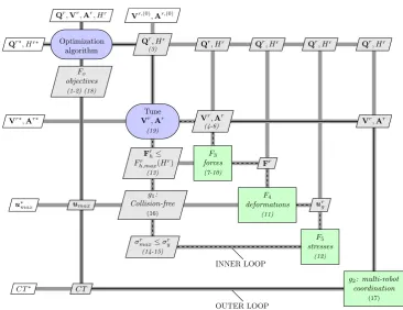
The proposed methodology is developed to solve the prob-lem formulated in Section4, and thus to find the optimal design for the structure of the end-effectors and to co-adapt the motion planning for the multi-robot material handling systems with compliant parts. The proposed optimisation methodology makes use of anAsymmetric Subspace Opti-misation (ASO)architecture according to the classification proposed in the survey of multi-disciplinary design opti-misation architectures presented by Martins and Lambe (2013). The choice for ASO is motivated by that the col-lision detection simulation for the multi-robot coordination requires an order of magnitude more time to complete than evaluating the other constraints concerning the robot trajectories. Henceforth, it becomes beneficial to tune the trajectories within an inner optimisation loop by utilising the ASO architecture (Martins and Lambe2013). The eXtended Design Structure Matrix (XDSM) diagram (Lambe and Martins 2012) of the ASO architecture for the proposed methodology is shown in Fig.4. The XDSM diagram shows both the data dependencies (thick grey lines) and process flows (black thin dashed lines indicate the inner loop, and black thin full lines the outer loop). In the diagram, the rectangles represent the process steps of the methodology, the parallelograms show data inputs and outputs, and the rounded rectangles indicatedriversthat control the iterative processes.
In the model formulation, the optimisation variables are the parameters of the motion planning (Qr,Vr,Ar) and the
design of the end-effectors (Hr). Asolutionrefers to a set of values for the optimisation variables. During the optimisa-tion, different trial-solutions are iteratively generated by an optimisation algorithm. The formulated model is then used to determine theobjective function valuesof each solution, using its values. As defined in the formulation of the objec-tive function in (1), the cycle-time is the primary objecobjec-tive function value, and the maximum part deformation is the secondary. Onlyfeasible solutions, which are solutions that agree with all constraints of the problem, are considered during the optimisation and infeasible ones are directly dis-carded. When comparing the objective function values of the different feasible solutions, the cycle-time is prioritised, meaning that a solution with a shorter cycle-time is always considered as better than others with a longer cycle-time. Only when the cycle-time of the solutions is equal, the one with a smaller maximum deformation is considered better.
In other words, a solution S1 is considered better than a solutionS2if one of the following two statements holds true
CT (S1) < CT (S2)or
CT (S1) =CT (S2)andumax(S1)≤umax(S2)
(18)
where CT (Si) represents the cycle-time with solution Si
and umax(Si) the maximum deformation of the handled
parts with solutionSi.
The proposed optimisation methodology consists of two nested loops, anouter- and an inner-loop. The outer-loop includes the optimisation algorithm and handles generating the end-effector designs and robot paths, and the time-delay coordination after the trajectories are determined during the inner-loop. The outer-loop is thus concerned with only the optimisation variables related to the end-effector designs and robot paths, i.e. Qr and Hr. The inner-loop handles generating, tuning and verifying the trajectories and is thus concerned with only the variables related to the robots’ velocities and accelerations, i.e.Vr andAr.
5.1 Outer-loop
The outer-loop starts with the optimisation algorithm, which generates different solutions for the variables Qr andHr.
One iteration of the outer-loop relates to the evaluation of a solution. It starts with generating the end-effector designs and the robot paths according to the values of the trial-solution that is under evaluation. More specifically, for the end-effector designs, this includes representing the geome-tries for the collision detection simulation, and how these hold the handled plates for the FEA. This furthermore includes generating and verifying the paths.
Next, the inner-loop is deployed to determine the veloci-ties and accelerations for the trajectory of each robot along its path. The result of the inner-loop are tuned trajectories that are verified for the holding force, collisions, and plastic deformations. The inner-loop calculates the objective func-tion value for maximum deformafunc-tion (umax). Thereafter,
when verified trajectories for all operations are available, the outer-loop continues.
Fig. 4 XDSM Diagram for the ASO architecture of the proposed optimisation methodology (dashed line indicate the inner loop, and full line the outer loop of the proposed methodology)
coordination space, the coordination method effectively cal-culates the minimal time-delay between the start of the two robots so that these will not collide. This is done for each pair of robots that perform consecutive operations in the shared workspace. These minimal time-delays are after-wards adjusted to take into account the availability of the robots, i.e. that a robot can only start an operation when it has completed its previous operation. Combining the resulting time-delays for all operations gives the system’s cycle-time. The cycle-time, together with the maximum deformation value (Umax), are returned to the optimisation
algorithm.
5.2 Inner-loop
The task of the inner-loop is thus to generate, tune and ver-ify the trajectory of each robot operation along the provided path that was generated earlier in the outer-loop. Hence, it is concerned with determining the values that specify the optimisation variablesVr andAr. Since, the primary objec-tive is reducing the cycle-time, the trajectories are initially generated at the maximum velocity and acceleration of the robot.
Based on the simulated trajectory, the force on the part, the maximum stress, and the part deformations are calcu-lated respectively using (7), (15), and (11). This provides the information to verify the holding force constraint (13),
the yield stress constraint (14), and the collision constraint (16). As presented in the problem formulation, these are proportional with the velocity and/or acceleration of the robot along the trajectory. Therefore, when one of these constraints is violated, the velocity and acceleration for the trajectory are adaptively tuned in order to remove the vio-lation. Reducing the velocity and acceleration will reduce the force on the part, the maximum induced stress, the part deformations. The velocity and/or acceleration is decreased for the corresponding segment of the trajectory where the constraint violation occurs. The tuning of the velocity and acceleration are done as follows
vnew([ssr. . . ser])=vold([ssr. . . ser])−εv
anew([ssr. . . ser])=aold([ssr. . . ser])−εa (19)
where[ssr. . . ser]are the indices of the trajectory segments
where the constraint violation occurs, and εv and εa are
the step-sizes for decreasing respectively the velocity and accelerations for the tuning.
[image:9.595.112.479.53.335.2]When successful, the inner-loop generates a verified tra-jectory along the provided path for each robot operation, at the highest possible velocity and acceleration according to the constraints. The velocity and acceleration is as high as possible to reduce the duration of the operation, because reducing the cycle-time is the primary objective. The pro-posed optimisation methodology then continues with the outer-loop.
6 Implementation
This section presents the implementation of the proposed methodology for the case study. The sheet metal part in the case study is an inner side panel of the floor frame for a car body. The plate’s material is DP800 steel. Some optimisation variables can only be parametrised indirectly for the case study because these are not directly accessi-ble, which is common with real-world systems. A robot path (Qr) is specified by “via-locations” (yz-coordinates and zone radius), indicated as L1...4in Fig.5. Based on these via-locations, the path is then generated according to the robot controller, using a model. For the robots in the press line, there are four via-locations that, together with the pick-and place-locations, make up the path.
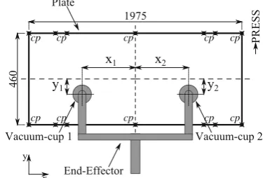
Furthermore, the parametrisation of the end-effectors (Hr), which defines the locations of the vacuum-cups on the plate is illustrated in Fig.6. The end-effectors always have two vacuum-cups in the case study, one at coordinates (x1, y1) and another one at (x2, y2). For constructing the RSM of the Yield Stress Constraint, it was found that 100 samples and using a 4thdegree polynomial provides suffi-cient accuracy, i.e. theroot-mean-squared error (RMSE)is 16.35 MPa and the normalisedRMSEis 0.061.
6.1 Outer loop
The outer loop starts with the optimisation algorithm, which is the Constructive Cooperative Coevolutionary Differential Evolution (C3ijDErpo) proposed by Glorieux et al. (2015b).
Fig. 5 Illustration of the robot path for the material handling in the press line
cp cp cp
cp cp cp cp
cp
cp cp
Fig. 6 Top-view of the handled blank sheet metal plate and the end-effector design (cpindicates the critical points for the collision detection)
The problem needs to be decomposed into subproblems in advance for the C3ijDErpo algorithm. For the case study, each subproblem corresponds to a robot in sys-tem. C3ijDErpo optimises the subproblems separately in cooperative fashion in order to co-adaptively attune the opti-misation variables of the subproblems and thereby consider the inter-dependencies between them. C3ijDErpo is partic-ularly suitable for large-scale optimisation problems with inter-dependent subproblems, i.e. non-fully separable sub-problems (Glorieux et al.2015b). This makes it suitable for the press line case study, as show by Glorieux et al. (2015a). The population size is 20, and the termination criterion is 1000 evaluations.
The evaluation of a solution starts with generating the robot paths (Qr), based on the specified parameters (eight per robot) for the via-locations. This is done accurately using a model of the 2D-belt Binar Unifeeder robot con-troller. A description of this model is given by Glorieux et al. (2015c). The end-effector designs are generated based on the parameters (two per end-effector) that specify the designs’ variables (Hr).
In the final step of the outer loop, the time-delays are calculated for the multi-robot coordination. The collision detection simulation is done using the Proximity Query Package (PQP) (Larsen et al. 2000), which is a software library for proximity queries, including collision detection of a pair of geometric models composed of triangles. The used geometric models are the 3D CAD models of the geometries of the robots and press dies in the real-world press line. These are simplified to only consider the rele-vant geometrical elements in order to expedite the collision detection simulation.
6.2 Inner loop
[image:10.595.329.517.62.189.2] [image:10.595.55.286.585.687.2]2015a). It then calculates the force on the part during han-dling. Since they are flat blank sheet metal plates that are always held horizontally, it can be assumed that the force in vertical direction has a significantly larger influence than the force in horizontal direction. The presented formula-tion focuses therefore only on the vertical force, which is the combination of the acceleration-caused inertia force (i.e. gravity and robot accelerations) as in (9), and the air resis-tance force as in (10). The diameter of the end-effectors’ vacuum-cups is 105mmand the maximum holding force is 236 N in normal direction (i.e.z-axis). Both the holding force and yield stress constraint can then be verified when the force on the part is known.
Next is the transient response analysis to estimate the dynamic deformation of the part during handling. This also gives the maximum part deformation objective function value. The Variation Response Method (VRM)(Franciosa and Ceglarek2016), a physics-driven modeller with FEA-based kernel, is used in this work because of its advanced capabilities to parametrise key aspects including the load-ing force, part’s compliance, end-effector, and vacuum-cups (Franciosa and Ceglarek2015; Franciosa et al.2016). The vacuum-cups are modelled as a set of rigid points in a circular pattern. It is assumed that the positions of the vacuum-cups relative to the plate are fixed during handling and are identical for each cycle. To reduce the FEA’s com-putation time, only the deformations of critical points on the plate are calculated. These critical points are the first to interfere with the obstacles or other robots when collid-ing. The critical points (shown in Fig.6) are on the plate’s outer border at the corners, at the centres inx-direction, and where it will collide with the guiding pins of the lower die (as shown in Fig.1).
The next step is the collision detection simulation between the obstacle(s) and the dynamic deformation of the part, end-effector and robot, which is also done using the PQP library (Larsen et al.2000).
If the constraints are not met, the next step is tuning the corresponding robot’s velocity and acceleration along the trajectory. The velocity and acceleration in the correspond-ing segment (five per operation) of the trajectory are tuned according to (19). When all constraints are met, the tra-jectories are returned to the outer loop for the multi-robot coordination.
7 Tests
Several tests have been performed to illustrate the pur-pose and the advantage of the propur-posed methodology. More specifically, the goal is to demonstrate the gain in produc-tivity by co-adaptively designing the end-effectors with the robot motion planning, i.e. the contribution of the proposed
methodology. Secondarily, the tests also demonstrate that it is critical to consider the deformations of the compliant parts in order to plan reliable robot motions for the multi-robot system in this case study, i.e. the need for the proposed methodology. Three different tests are performed for this. The optimisation for each test has been repeated 10 times in order to obtain a statistically reliable result, which is neces-sary because the used optimisation algorithm is stochastic. In the first test, the methodology is deployed as proposed for the considered case study.
In the second test, the robot motions are planned for com-pliant parts but using a default end-effector design, which is based on the end-effector that is used in the real-world press line, withx1,x2=493.75mmandy1,y2 =0.0mm. Only the via-locations of the path and the robot trajectory vari-ables (velocities and accelerations) are optimised in this test. This provides a reference for a comparison with the first test to demonstrate the importance of the optimised end-effector designs.
In the third test, the robot motion planning is performed assuming that the parts are rigid and using the default end-effector design. The yield stress constraint from (14) is thus ignored in this test. The found optimal solution in this test is analysed to reveal the consequences of assuming that the parts are rigid, which demonstrates the need for considering the deformations of the compliant parts during handling.
8 Results and discussion
This section discusses and compares the results of the three different tests performed in this work. The results of the optimal solution found by the optimisation are the objective function values for the maximum part deformationumaxand
the cycle-timeCT. The mean and standard deviation (std) of the results across the repetitions are shown in Table 2, where the productivity of the solutions is also given as pro-duction rate (PR), which is expressed in parts per minute ([pr/min]).
[image:11.595.306.544.627.718.2]The optimal solution in Test 1 has an end-effector design with x1, x2 equal to 516.6 mm and y1, y2 equal to 87 mm. The location of the vacuum-cups on the plate are thus
Table 2 Comparison of the part deformation (umax), cycle-time (CT),
and production rate (PR) results, (result of Test 3 is infeasible)
Test umax[mm] CT [s] PR PR
mean std mean std [pr/min] [%]
1 −25.2 7.6 4.074 0.005 14.73 0.0
2 −21.8 0.5 4.153 0.003 14.45 −1.9
3 −22.1 0.5 4.132 0.003 14.52 −1.4
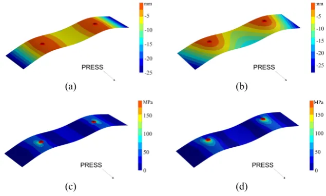
moved to the outside of the plate inx-direction and away from the centre of the plate iny-direction. When compar-ing Test 1 with Test 2, it can be seen in Table2that there is a relatively small difference between the maximum part deformation. This was further investigated by FEA and visu-alised as shown in Fig.7, together with the difference in induced stress. Table 2 also shows that the cycle-time is longer in Test 2 than in Test 1, which results in a produc-tivity that is 1.9% higher in Test 1. Although this difference in productivity might seem minor at first sight, this is nev-ertheless a substantial improvement considering that the press line is used for high-volume production. In fact, the 1.9% increase in productivity means that 134 more parts are produced during 8 hours. This thus shows that the productiv-ity is significantly improved by designing the end-effector co-adaptively with the multi-robot motion planning.
When looking at the optimal solution found in Test 3 in Table2, it is very interesting to see that its productivity is lower than Test 1 (i.e. -1.4%), and only slightly higher than Test 2. Note that the only difference between Test 2 and 3 is the parts are assumed to be rigid. This indicates that, in Test 1, the increased productivity with the opti-mised end-effector designs is mainly related to the shorter time-delays for the multi-robot coordination, and less to the part deformations or holding force. This further confirms the contribution of the proposed methodology, i.e. design-ing the end-effectors co-adaptively with multi-robot motion planning.
The optimal solution found in Test 3 is also further anal-ysed by simulating it without the assumption that the parts are rigid. This showed that there are multiple collisions between the deformed part and the lower-die obstacle. Addi-tionally, the maximum induced stress in the part due to the dynamic deformations exceeds the yield stress of the material. Hence, the handled part would undergo plastic
deformations that damage it. This shows that planning the motions whilst considering the parts as rigid is highly unreliable.
An additional analysis of the optimal solution in Test 3 is performed to replicate the effect of Test 3 for an indus-trial scenario. Modifying the robot paths is an elaborate task, whereas changing the robot velocity can typically easily be done online. Hence, for this scenario, only the robot veloc-ities are tuned to avoid those problems (i.e. collisions and plastic deformations) in Test 3, and then the multi-robot coordination is consequently adjusted. The result of this is shown as Test 3a in Table 2. It can be seen that the pro-ductivity is now significantly lower, i.e. -4.2% compared to Test 1. Unreliable motion planning can result in a sub-stantially lower productivity than anticipated for during the planning, which is a problematic issue for the industry.
The proposed methodology addresses the lack of reliable systematic methods to design the end-effectors whilst co-adaptively plan the material handling motions in order to improve the productivity and maintain the products’ dimen-sional quality. There are several advantages compared to the current industrial practise. Besides the improved productiv-ity, the proposed methodology relies on digital tools (i.e. models, simulations, and algorithms) and can thus be used offline before launching the production of a new part. It avoids the need for the time-consumingad-hoconline trial-and-error, which is very expensive for press lines such as in the case study. In other words, the proposed methodology provides right-first-timesolutions for the motion planning and end-effectors design.
Although the case study only considers a single isolated press with two robots, the proposed methodology is directly applicable to entire press lines with multiple presses and press tending robots, with additional coordination between the unloading and the loading of consecutive presses.
Fig. 7 Comparison maximum part deformation withadefault andboptimised end-effector design, and comparison of the induced stress withcdefault and
doptimised end-effector design (red dots indicate the
vacuum-cups)
(a) (b)
[image:12.595.228.546.527.718.2]9 Summary and conclusions
Multi-robot material handling of compliant parts is a chal-lenging task in manufacturing automation. The critical issue is the deformations of the parts during handling, which is affected by both the end-effector design and the motion planning. This paper focuses on improving the productiv-ity of multi-robot material handling systems by designing the structure of the end-effectors co-adaptively with the motion planning for the robot paths and trajectories. A novel multi-disciplinary methodology that enables this co-adaptive simultaneous optimisation is proposed. The for-mulation for modelling this multi-disciplinary optimisation problem is presented, together with a detailed description of the proposed methodology’s procedure.
The objectives of the methodology are to find the shortest cycle-time and smallest part deformations. The optimisation variables are the robot paths, trajectories, and end-effector designs. The constraints for the optimisation are to avoid parts being dropped, plastic part deformations, and colli-sions. The dynamic part deformations are considered during the collision detection simulation. Finally, a multi-robot coordination method determines the minimal relative start-ing time-delays for each operation to avoid collisions in the shared workspace and thereby also the shortest cycle-time.
The proposed methodology was evaluated for a real-world industrial case study that considers the multi-robot material handling system of a multi-stage tandem sheet metal press line. This demonstrates the need and contribu-tion of the proposed methodology, i.e. that the parts’ compli-ance must be considered and that substantial improvements in productivity can be achieved by co-adaptively optimis-ing the end-effector designs and robot motion plannoptimis-ing. The latter is the specific novelty of the proposed methodology compared to other exciting methods.
The unique element of this work is that the resulting end-effector designs are not only optimised for holding the handled parts but also for the collision-avoidance between the robots that are operating simultaneously in the shared workspace. This can have a significant influence on the productivity of the considered system, as demonstrated by conducted tests for the case study.
Future work could include a broader optimisation of the end-effector design, i.e. changing the number and type of vacuum-cups, and consider other mechanisms to hold parts such as clamps, fingers, shovels etc.
Acknowledgements The authors thank Nima K. Nia and Volvo Cars Corporation for their support and industrial insights concerning sheet metal press lines. This work was performed at the Digital LifeCycle Management (DLM) research group of WMG at University of War-wick in Coventry (UK), and supported byV¨astra G¨otalandsregionen
(Sweden), under the grant PROSAM+ RUN 612-0208-16.
Open Access This article is distributed under the terms of the Creative Commons Attribution 4.0 International License (http:// creativecommons.org/licenses/by/4.0/), which permits unrestricted use, distribution, and reproduction in any medium, provided you give appropriate credit to the original author(s) and the source, provide a link to the Creative Commons license, and indicate if changes were made.
References
Bien Z, Lee J (1992) A minimum-time trajectory planning method for two robots. IEEE Trans Robot Autom 8(3):414–418
Binar Olofstr¨om AB (2014) Binar Press Automation -UniFeeder. http://shop.binarolofstrom.se.k34.itc.se/index.php? id product=2&controller=product&id lang=1
Ceglarek D, Li HF, Tang Y (2001) Modeling and optimization of end effector layout for handling compliant sheet metal parts. ASME J Manuf Sci Eng 123(3):473–480
Datta R, Jain A, Bhattacharya B (2016) A piezoelectric model based multi-objective optimization of robot gripper design. Struct Mul-tidisc Optim 53(3):453–470
Feng X, Patel R, Pons R, Casanelles R, Wappling D, Westrom J, Andersson H (2013) Optimization-based development of ultra high performance Twin Robot Xbar press tending robot system. In: 44th international symposium on robotics, pp 1–8
Franciosa P, Ceglarek D (2015) Hierarchical synthesis of multi-level design parameters in assembly system. CIRP Ann Manuf Technol 64(1):149–152
Franciosa P, Ceglarek D (2016) VRM Simulation toolkit. http:// www2.warwick.ac.uk/fac/sci/wmg/research/manufacturing/downloads/ Franciosa P, Das A, Ceglarek D, Bolognese L, Marine C, Mistry A (2014) Design synthesis methodology for dimensional manage-ment of assembly process with compliant non-ideal parts. In: Pro-ceedings of joint conference on mechanical, design engineering & advanced manufacturing
Franciosa P, Gerbino S, Ceglarek D (2016) Fixture capability optimi-sation for early-stage design of assembly system with compliant parts using nested polynomial chaos expansion. Procedia CIRP 41:87–92
Glorieux E, Danielsson F, Svensson B, Lennartson B (2015a) Con-structive cooperative coevolutionary optimisation for interacting production stations. Int J Adv Manuf Technol 80(1-4):673–688 Glorieux E, Svensson B, Danielsson F, Lennartson B (2015b)
Improved constructive cooperative coevolutionary differential evolution for large-scale optimisation. In: IEEE symposium on differential evolution, pp 3719–3726
Glorieux E, Svensson B, Danielsson F, Lennartson B (2015c) Simulation-based time and jerk optimisation for robotic press tending. In: 29th European simulation and modelling conference, EUROSIS, pp 377–384
Glorieux E, Svensson B, Danielsson F, Lennartson B (2016) Multi-objective constructive cooperative coevolutionary optimization of robotic press-line tending. Eng Optim 0(0):1–19
Hoffmann H, Kohnh¨auser M (2002) Strategies to optimize the part transport in crossbar transfer presses. CIRP Ann Manuf Technol 51(1):27–32
Jansson T, Nilsson L, Redhe M (2003) Using surrogate models and response surfaces in structural optimization – with application to crashworthiness design and sheet metal forming. Struct Multidisc Optim 25(2):129–140
Kavraki LE, LaValle SM (2008) Motion planning. In: Siciliano B, Khatib O (eds) Springer handbook of robotics. Springer, Berlin, pp 109–131
Lambe AB, Martins JRRA (2012) Extensions to the design structure matrix for the description of multidisciplinary design, analysis, and optimization processes. Struct Multidisc Optim 46(2):273–284 Larsen E, Gottschalk SC, Lin M, Manocha D (2000) Fast proximity queries with swept sphere volumes. In: Proceedings of the IEEE international conference on robotics, pp 3719–3726
Li H, Ceglarek D (2002) Optimal trajectory planning for material handling of compliant sheet metal parts. ASME J Mech Des 124(2):213–222
Li HF, Ceglarek D, Shi J (2002) A dexterous part-holding model for handling compliant sheet metal parts. ASME J Manuf Sci Eng 124(1):109–118
Liao X, Wang GG (2003) Evolutionary path planning for robot assisted part handling in sheet metal bending. Robot Comput Integr Manuf 19(5):425–430
Mantriota G, Messina A (2011) Theoretical and experimental study of the performance of flat suction cups in the presence of tangential loads. Mech Mach Theory 46(5):607–617
Martins JR, Lambe AB (2013) Multidisciplinary design optimization: a survey of architectures. AIAA J 51(9):2049–2075
Patel R, Pons R, Casanelles R, Westrom J, Andersson H, Wappling D, Feng X (2013) Model driven mechatronic design optimization of a linear axis press tending robot. In: 44th international symposium on robotics, pp 1–4
Pettersson M, Olvander J, Andersson H (2007) Application¨ adapted performance optimization for industrial robots. In: IEEE international symposium on industrial electronics, pp 2047– 2052
Platzer M, Feng X, Wappling D, Baumli N, Patel R, Pons R, Casanelles R, Westrom J (2013) New robot concept for ultra high performance press tending robot system. In: 44th international symposium on robotics, pp 1–3
Schmalz J, Giering L, H¨olzle M, Huber N, Reinhart G (2016) Method for the automated dimensioning of gripper systems. Procedia CIRP 44:239–244
Shan S, Wang G (2010) Survey of modeling and optimiza-tion strategies to solve high-dimensional design problems with computationally-expensive black-box functions. Struct Multidisc Optim 41:219–241. 2
da Silva AM (2015) Mechatronics design process with energy opti-mization for industrial machines doctoral thesis. Marquette Uni-versity, Wisconsin
Tuleja P, Sidlovsk´a L (2014) Unilateral gripping with active vacuum suction cup: calculation of gripping force and number of suction cups. Tech Rep.: Transfer inov´aci´ı 29/2014. Technical University of Kosice, Slovakia
Wang H, Fan T, Li G (2017) Reanalysis-based space mapping metho, an alternative optimization way for expensive simulation-based problems. Struct Multidisc Optim 55:2143–2157