ScienceDirect
Available online at Available online at www.sciencedirect.comwww.sciencedirect.com
ScienceDirect
Energy Procedia 00 (2017) 000–000
www.elsevier.com/locate/procedia
1876-6102 © 2017 The Authors. Published by Elsevier Ltd.
Peer-review under responsibility of the Scientific Committee of The 15th International Symposium on District Heating and Cooling.
The 15th International Symposium on District Heating and Cooling
Assessing the feasibility of using the heat demand-outdoor
temperature function for a long-term district heat demand forecast
I. Andrić
a,b,c*, A. Pina
a, P. Ferrão
a, J. Fournier
b., B. Lacarrière
c, O. Le Corre
c aIN+ Center for Innovation, Technology and Policy Research - Instituto Superior Técnico, Av. Rovisco Pais 1, 1049-001 Lisbon, PortugalbVeolia Recherche & Innovation, 291 Avenue Dreyfous Daniel, 78520 Limay, France
cDépartement Systèmes Énergétiques et Environnement - IMT Atlantique, 4 rue Alfred Kastler, 44300 Nantes, France
Abstract
District heating networks are commonly addressed in the literature as one of the most effective solutions for decreasing the greenhouse gas emissions from the building sector. These systems require high investments which are returned through the heat sales. Due to the changed climate conditions and building renovation policies, heat demand in the future could decrease, prolonging the investment return period.
The main scope of this paper is to assess the feasibility of using the heat demand – outdoor temperature function for heat demand forecast. The district of Alvalade, located in Lisbon (Portugal), was used as a case study. The district is consisted of 665 buildings that vary in both construction period and typology. Three weather scenarios (low, medium, high) and three district renovation scenarios were developed (shallow, intermediate, deep). To estimate the error, obtained heat demand values were compared with results from a dynamic heat demand model, previously developed and validated by the authors.
The results showed that when only weather change is considered, the margin of error could be acceptable for some applications (the error in annual demand was lower than 20% for all weather scenarios considered). However, after introducing renovation scenarios, the error value increased up to 59.5% (depending on the weather and renovation scenarios combination considered). The value of slope coefficient increased on average within the range of 3.8% up to 8% per decade, that corresponds to the decrease in the number of heating hours of 22-139h during the heating season (depending on the combination of weather and renovation scenarios considered). On the other hand, function intercept increased for 7.8-12.7% per decade (depending on the coupled scenarios). The values suggested could be used to modify the function parameters for the scenarios considered, and improve the accuracy of heat demand estimations.
© 2017 The Authors. Published by Elsevier Ltd.
Peer-review under responsibility of the Scientific Committee of The 15th International Symposium on District Heating and Cooling.
Keywords:Heat demand; Forecast; Climate change
Energy Procedia 145 (2018) 458–463
1876-6102 Copyright © 2018 The Authors. Published by Elsevier Ltd.
Selection and peer-review under responsibility of the scientific committee of the Applied Energy Symposium and Forum, Renewable Energy Integration with Mini/Microgrids, REM 2017
10.1016/j.egypro.2018.04.091
10.1016/j.egypro.2018.04.091 1876-6102
Copyright © 2018 The Authors. Published by Elsevier Ltd.
Selection and peer-review under responsibility of the scientific committee of the Applied Energy Symposium and Forum, Renewable Energy Integration with Mini/Microgrids, REM 2017
Available online at www.sciencedirect.com
ScienceDirect
Energy Procedia 00 (2018) 000–000
www.elsevier.com/locate/procedia
1876-6102 Copyright © 2018 Elsevier Ltd. All rights reserved.
Selection and peer-review under responsibility of the scientific committee of the Applied Energy Symposium and Forum, Renewable Energy Integration with Mini/Microgrids, REM 2017.
Applied Energy Symposium and Forum, Renewable Energy Integration with Mini/Microgrids,
REM 2017, 18
–
20 October 2017, Tianjin, China
A practical low-cost approach to build membrane electrode
assemblies using decal transfer technique
Sichang Yang
a, Xinyu Zhang
a,b,*, Bo Wang
b, Hanzhe Huang
a, Zirui Zhao
a, Xinyuan
Wang
a, Kaili Yu
a, Goodarz Ahmadi
c aResearch Center for Fluids and Thermal Engineering, University of Nottingham Ningbo China, 199 Taikang East Road; 315100 Ningbo, China bInternational Doctoral Innovation Centre, University of Nottingham Ningbo China,199 Taikang East Road, 315100 Ningbo, China
cDepartment of Mechanical and Aeronautical Engineering, Clarkson University, Potsdam, New York, USA
Abstract
Membrane electrode assembly (MEA) is the heart of a proton exchange membrane (PEM) fuel cell. In this paper, a practical and low-cost approach to build membrane electrode assemblies in lab using decal transfer technique is described and verified. The procedure is based on current literatures but using different materials for convenience and cost-saving. All devices and tools used are easy to find in normal labs and all materials used are affordable and easy to obtain from market. Two Membrane electrode assemblies are built and tested using a PEM fuel cell test and control system. Two MEAs showed voltages of about 0.82V and 0.70V respectively, measured with a digital multimeter, which are lower than that of the commercial MEA. It is found that the unscratched MEA with more catalyst has a lower voltage, but can generate higher current density and much water. Some water oozed through the bipolar plates which usually is not seen in a single cell test
Copyright © 2018 Elsevier Ltd. All rights reserved.
Selection and peer-review under responsibility of the scientific committee of the Applied Energy Symposium and Forum, Renewable Energy Integration with Mini/Microgrids, REM 2017.
Keywords: Build; membrane electrode assemblies; decal transfer technique
* Corresponding author. Tel.: +86-18058261662; fax: +86(0)574 8818 0175.
E-mail addresses: [email protected] (X. Zhang),
2 Sichang Yang, Xinyu Zhang, Bo Wang, Hanzhe Huang, Zirui Zhao, Xinyuan Wang, Kaili Yu, et el. / Energy Procedia 00 (2018) 000–000
1. Introduction
PEM fuel cells with renewable hydrogen fuels can be used to build PEM fuel cell power plants (FCPPs) in isolated or remote areas as stand-alone or grid connected applications. Compared to experimental study, numerical simulations through CFD technique can provide in-depth understanding of electrochemical reactions inside fuel cells thus have become increasingly hot in fuel cell study. However, due to serious lack of published parameter and property data for membrane electrode assembly (MEA) which is the heart of a proton exchange membrane (PEM) fuel cell, it is very difficult to verify the modeling and simulation results. A practical way to solve this problem is to build one’s own MEA so that one can have all the parameter and property data available for model input and verification. In this case, it is important to find a practical and low-cost approach to build membrane electrode assemblies in lab using available devices, tools and materials. This paper is not intended to create a new approach to build MEAs. The objective of this work is to find or combine and verify a practical and low-cost approach to build membrane electrode assemblies using easily available devices, tools and materials in lab from the existing approaches.
A five-layer MEA consists of a polymer electrolyte membrane in the center, two gas diffusion layers made of carbon or graphite fabric and two catalyst layers which are deposited onto or into the gas diffusion layer or polymer electrolyte membrane. Normally the catalyst is platinum catalyst. Tian et al. [1] summarized that MEA preparation methods can be classified into two categories, catalyst-coated substrate (CCS) and catalyst coated membrane (CCM) methods. Tian et al. [1] indicated that usually there are five methods to deposit the platinum catalyst into the gas diffusion layer or the membrane: sputtering, spraying, decal, impregnation-reduction and screen printing. Hurley [2] indicated more methods including Benjamin Franklin technique, electrochemical deposition (ECD), electroless deposition, mechanical deposition, electrostatic dispersion, simple mixing and photochemical deposition. Among all the methods mentioned above, the decal method is considered to be the easiest way to manufacture MEA on a large scale [1]. This method is adopted in this work because it requires less equipments and all equipments are available in normal labs. The additional materials needed are also easy to obtain from online market. Thus this method is more practical for one to build one’s own MEA in normal labs. Hephas energy [3] provides a detailed description on MEA Manufacturing process. Xia et al. [4] reported a Nafion emulsion method for MEA. They use 5 % (by mass) Nafion alcohol solution and non-polar solvent to produce Nafion emulsion. The catalyst ink using this Nafion emulsion can be directly cast onto Nafion membrane to make MEA. This method is simple and can prevent the Nafion membrane swelling, thus is also suitable for large-scale application.
The method described in this study is based on methods of Hurley [2], Hephas energy [3] and Xia et al. [4]. The procedure is similar but some time and material quantity in operation are different due to variation of lab condition. Many materials are also changed due to availability and cost reason.
2.Methodology
2.1. Preparation
2.1.1 Mechanical tools:
• Ruler: Use to measure the size of Nafion membrane, Teflon transfer plate and gas diffusion layer; • Scissors: Use to get parts of Nafion membrane and Teflon transfer plates in suitable size.
2.1.2 Chemical tools:
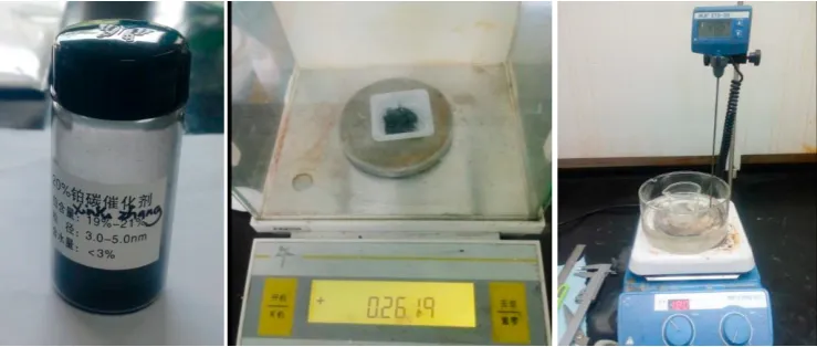
• Beaker, measuring cylinder, conical flask, dropper, water bath machine, magnetic stirrers, electronic balance. Beaker and conical flash are the containers where the reactions will happen inside. Measuring cylinder, dropper and electronic balance are used to get an accurate quantity of chemical reagents. All the reactions will be happening with an environment provided by magnetic stirrers. Fig. 1 shows Pt/C (20%Pt) catalyst, electronic balance, Water bath and magnetic stirrer.
Sichang Yang et al. / Energy Procedia 145 (2018) 458–463 459 Available online at www.sciencedirect.com
ScienceDirect
Energy Procedia 00 (2018) 000–000
www.elsevier.com/locate/procedia
1876-6102 Copyright © 2018 Elsevier Ltd. All rights reserved.
Selection and peer-review under responsibility of the scientific committee of the Applied Energy Symposium and Forum, Renewable Energy Integration with Mini/Microgrids, REM 2017.
Applied Energy Symposium and Forum, Renewable Energy Integration with Mini/Microgrids,
REM 2017, 18
–
20 October 2017, Tianjin, China
A practical low-cost approach to build membrane electrode
assemblies using decal transfer technique
Sichang Yang
a, Xinyu Zhang
a,b,*, Bo Wang
b, Hanzhe Huang
a, Zirui Zhao
a, Xinyuan
Wang
a, Kaili Yu
a, Goodarz Ahmadi
c aResearch Center for Fluids and Thermal Engineering, University of Nottingham Ningbo China, 199 Taikang East Road; 315100 Ningbo, China bInternational Doctoral Innovation Centre, University of Nottingham Ningbo China,199 Taikang East Road, 315100 Ningbo, China
cDepartment of Mechanical and Aeronautical Engineering, Clarkson University, Potsdam, New York, USA
Abstract
Membrane electrode assembly (MEA) is the heart of a proton exchange membrane (PEM) fuel cell. In this paper, a practical and low-cost approach to build membrane electrode assemblies in lab using decal transfer technique is described and verified. The procedure is based on current literatures but using different materials for convenience and cost-saving. All devices and tools used are easy to find in normal labs and all materials used are affordable and easy to obtain from market. Two Membrane electrode assemblies are built and tested using a PEM fuel cell test and control system. Two MEAs showed voltages of about 0.82V and 0.70V respectively, measured with a digital multimeter, which are lower than that of the commercial MEA. It is found that the unscratched MEA with more catalyst has a lower voltage, but can generate higher current density and much water. Some water oozed through the bipolar plates which usually is not seen in a single cell test
Copyright © 2018 Elsevier Ltd. All rights reserved.
Selection and peer-review under responsibility of the scientific committee of the Applied Energy Symposium and Forum, Renewable Energy Integration with Mini/Microgrids, REM 2017.
Keywords: Build; membrane electrode assemblies; decal transfer technique
* Corresponding author. Tel.: +86-18058261662; fax: +86(0)574 8818 0175.
E-mail addresses: [email protected] (X. Zhang),
Available online at www.sciencedirect.com
ScienceDirect
Energy Procedia 00 (2018) 000–000
www.elsevier.com/locate/procedia
1876-6102 Copyright © 2018 Elsevier Ltd. All rights reserved.
Selection and peer-review under responsibility of the scientific committee of the Applied Energy Symposium and Forum, Renewable Energy Integration with Mini/Microgrids, REM 2017.
Applied Energy Symposium and Forum, Renewable Energy Integration with Mini/Microgrids,
REM 2017, 18
–
20 October 2017, Tianjin, China
A practical low-cost approach to build membrane electrode
assemblies using decal transfer technique
Sichang Yang
a, Xinyu Zhang
a,b,*, Bo Wang
b, Hanzhe Huang
a, Zirui Zhao
a, Xinyuan
Wang
a, Kaili Yu
a, Goodarz Ahmadi
c aResearch Center for Fluids and Thermal Engineering, University of Nottingham Ningbo China, 199 Taikang East Road; 315100 Ningbo, China bInternational Doctoral Innovation Centre, University of Nottingham Ningbo China,199 Taikang East Road, 315100 Ningbo, China
cDepartment of Mechanical and Aeronautical Engineering, Clarkson University, Potsdam, New York, USA
Abstract
Membrane electrode assembly (MEA) is the heart of a proton exchange membrane (PEM) fuel cell. In this paper, a practical and low-cost approach to build membrane electrode assemblies in lab using decal transfer technique is described and verified. The procedure is based on current literatures but using different materials for convenience and cost-saving. All devices and tools used are easy to find in normal labs and all materials used are affordable and easy to obtain from market. Two Membrane electrode assemblies are built and tested using a PEM fuel cell test and control system. Two MEAs showed voltages of about 0.82V and 0.70V respectively, measured with a digital multimeter, which are lower than that of the commercial MEA. It is found that the unscratched MEA with more catalyst has a lower voltage, but can generate higher current density and much water. Some water oozed through the bipolar plates which usually is not seen in a single cell test
Copyright © 2018 Elsevier Ltd. All rights reserved.
Selection and peer-review under responsibility of the scientific committee of the Applied Energy Symposium and Forum, Renewable Energy Integration with Mini/Microgrids, REM 2017.
Keywords: Build; membrane electrode assemblies; decal transfer technique
* Corresponding author. Tel.: +86-18058261662; fax: +86(0)574 8818 0175.
E-mail addresses: [email protected] (X. Zhang),
2 Sichang Yang, Xinyu Zhang, Bo Wang, Hanzhe Huang, Zirui Zhao, Xinyuan Wang, Kaili Yu, et el. / Energy Procedia 00 (2018) 000–000
1. Introduction
PEM fuel cells with renewable hydrogen fuels can be used to build PEM fuel cell power plants (FCPPs) in isolated or remote areas as stand-alone or grid connected applications. Compared to experimental study, numerical simulations through CFD technique can provide in-depth understanding of electrochemical reactions inside fuel cells thus have become increasingly hot in fuel cell study. However, due to serious lack of published parameter and property data for membrane electrode assembly (MEA) which is the heart of a proton exchange membrane (PEM) fuel cell, it is very difficult to verify the modeling and simulation results. A practical way to solve this problem is to build one’s own MEA so that one can have all the parameter and property data available for model input and verification. In this case, it is important to find a practical and low-cost approach to build membrane electrode assemblies in lab using available devices, tools and materials. This paper is not intended to create a new approach to build MEAs. The objective of this work is to find or combine and verify a practical and low-cost approach to build membrane electrode assemblies using easily available devices, tools and materials in lab from the existing approaches.
A five-layer MEA consists of a polymer electrolyte membrane in the center, two gas diffusion layers made of carbon or graphite fabric and two catalyst layers which are deposited onto or into the gas diffusion layer or polymer electrolyte membrane. Normally the catalyst is platinum catalyst. Tian et al. [1] summarized that MEA preparation methods can be classified into two categories, catalyst-coated substrate (CCS) and catalyst coated membrane (CCM) methods. Tian et al. [1] indicated that usually there are five methods to deposit the platinum catalyst into the gas diffusion layer or the membrane: sputtering, spraying, decal, impregnation-reduction and screen printing. Hurley [2] indicated more methods including Benjamin Franklin technique, electrochemical deposition (ECD), electroless deposition, mechanical deposition, electrostatic dispersion, simple mixing and photochemical deposition. Among all the methods mentioned above, the decal method is considered to be the easiest way to manufacture MEA on a large scale [1]. This method is adopted in this work because it requires less equipments and all equipments are available in normal labs. The additional materials needed are also easy to obtain from online market. Thus this method is more practical for one to build one’s own MEA in normal labs. Hephas energy [3] provides a detailed description on MEA Manufacturing process. Xia et al. [4] reported a Nafion emulsion method for MEA. They use 5 % (by mass) Nafion alcohol solution and non-polar solvent to produce Nafion emulsion. The catalyst ink using this Nafion emulsion can be directly cast onto Nafion membrane to make MEA. This method is simple and can prevent the Nafion membrane swelling, thus is also suitable for large-scale application.
The method described in this study is based on methods of Hurley [2], Hephas energy [3] and Xia et al. [4]. The procedure is similar but some time and material quantity in operation are different due to variation of lab condition. Many materials are also changed due to availability and cost reason.
2. Methodology
2.1. Preparation
2.1.1 Mechanical tools:
• Ruler: Use to measure the size of Nafion membrane, Teflon transfer plate and gas diffusion layer; • Scissors: Use to get parts of Nafion membrane and Teflon transfer plates in suitable size.
2.1.2 Chemical tools:
• Beaker, measuring cylinder, conical flask, dropper, water bath machine, magnetic stirrers, electronic balance. Beaker and conical flash are the containers where the reactions will happen inside. Measuring cylinder, dropper and electronic balance are used to get an accurate quantity of chemical reagents. All the reactions will be happening with an environment provided by magnetic stirrers. Fig. 1 shows Pt/C (20%Pt) catalyst, electronic balance, Water bath and magnetic stirrer.
460 Sichang Yang et al. / Energy Procedia 145 (2018) 458–463
Sichang Yang, Xinyu Zhang, Bo Wang, Hanzhe Huang, Zirui Zhao, Xinyuan Wang, Kaili Yu, et el. / Energy Procedia 00 (2018) 000–000 3
• Hot-presser ZG-20I and thermometer. Hot-presser ZG-20I will provide a high temperature and high pressure environment for catalyst transfer. Thermometer will show the temperature in each step.
2.14 Materials:
• Hydrogen(H2) and Oxygen(O2): Used for testing the membrane electrode assemblies(MEA).
• 1Mol/L Sodium hydroxide(NaOH) solution 100ml: Used to get 1% Sodium hydroxide which will be used to deal with nafion 115 membrane.
• Enough deionized water: Wash the membrane and all the chemical tools.
• 30% Hydrogen peroxide (H2O2) solution 50ml: Used to get 3% Hydrogen peroxide solution which will be used to deal with nafion 115 membrane.
• 98% Sulfuric acid(H2SO4) solution 10g: Used to get 0.5Mol/L Sulfuric acid solution which will be used to deal with nafion 115 membrane and catalyst on it.
• Glycerine 10g, Pt/C(20%Pt) catalyst 1g (as shown in Fig.1): These are the major part to manufacture the final catalyst.
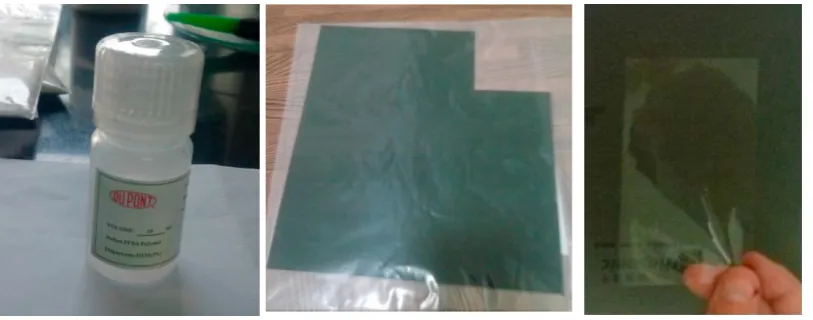
• Nafion 117 solution 10ml: This is also the major part to manufacture the final catalyst. This solution is produced by Dupont company in America.
• One piece of gas diffusion layer (GDL) 20cm*20cm.
• One piece of Nafion 115 membrane 10cm*10cm: One kind of proton exchange membrane which is the major part of membrane electrode assemblies. The membrane is produced by Dupont company in America. Fig. 2 shows Nafion 117 solution, GDL (gas diffusion layer) and Nafion 115 membrane.
• Two pieces of Teflon transfer plate 10cm*4cm: The transfer plate is used to transfer catalyst from the plate to the processed Nafion 115 membrane.
Fig. 1. Pt/C (20%Pt) catalyst, electronic balance, water bath and magnetic stirrer
2.2.Process of manufacture
• Use capillary tube to take 1g 5% Nafion 117 solution and place it in a conical bottle.
• Use capillary tube to take 0.25g catalyst (Pt/C(20%Pt)) solution and place it in the same conical bottle. • Use capillary tube to take about 2g glycerol and place it in the same conical bottle. Put the bottle on the magnetic stirrer and turn on the stirrer. After working for 15 minutes, take 1g glycerol and place it into the same bottle. Turn on the stirrer and let it work for 24 hours with the top of the conical bottle plugged. Store the mixture properly after stirring.
• Measure four 30mm*30mm Teflon transfer plates and cut them off from the original plate.
• Use a brush to paint on the transfer plate and make the catalyst distribute uniformly on one side of the transfer plate. The plate cannot afford two much wet catalyst on the plate because of the mobility of the catalyst.
4 Sichang Yang, Xinyu Zhang, Bo Wang, Hanzhe Huang, Zirui Zhao, Xinyuan Wang, Kaili Yu, et el. / Energy Procedia 00 (2018) 000–000
One can paint it for several times and dry it after painting, make the total mass of catalyst transferred to the plate is at least 0.2g/cm2.
Fig. 2.Nafion 117 solution, GDL and Nafion 115 membrane
• When enough catalyst has been transferred to the transfer plates, put the transfer plates into a vacuum oven and dry them at a temperature of 90 oC for 24 hours.
• After 24 hours, put the transfer plates with catalyst on it at a dry environment. When it is time to transfer the catalyst to the membrane, get them out.
• Measure two 40mm*40mm Nafion 115 membranes and cut them off from the original film.
• Put the membrane into a beaker, add 3% H2O2 solution in the beaker, use the water bath machine with the temperature at 90 oC to heat the fluid inside for 1 hour.
• Pour out the fluid inside, wash the membrane with deionized water, then add deionized water into the beaker with the membrane inside, use the water bath machine with the temperature at 90 oC to heat the fluid inside for 1.5 hour.
• Pour out the fluid inside, and add 1% NaOH solution into the beaker with the membrane in it. Use the water bath machine to heat the fluid inside for 1.5 hour at the temperature of 90 oC.
• Pour out the fluid inside, wash the membrane with deionized water, then add deionized water into the beaker with the membrane inside, use the water bath machine with the temperature at 90 oC to heat the fluid inside for 1 hour.
• Store the membrane obtained in the deionized water.
• Transfer the catalyst on Teflon transfer plate to the membrane after deal with NaOH and H2O2 solution. Take out the membrane and place it in the vacuum oven. Turn on the vacuum oven; heat the machine until the temperature is 130 oC. After 5 minutes, turn off the vacuum oven and get the dry membrane out; store it in dry plastic bag.
• After cooling down the membrane, settle two Teflon transfer plate with catalyst on both side of membrane. Add two Furon membrane on the other side of Teflon transfer plate and set the combined object on the steel plate of hot presser machine.
• Heat the assembly until it is 210 oC and set the pressure to 200 kg/cm2. Maintain the temperature and press the assembly in the following manner: press for 140s, release for 2s; press for additional 100s, release for 2s; finally press for another 60s. Overall the hot press period is 5 minutes. Then cool down the product at the same pressure. The catalyst will turn to the 112 membrane. Use a tweezers to move the Teflon transfer plates and Furon membrane away, the MEA membrane is done. Up to now, the catalyst has been added to the membrane and they have already been dried out. The MEA membrane now consists of three layers, i.e. the Nafion layer and catalyst layers on both sides.
[image:3.544.76.446.362.519.2]Sichang Yang et al. / Energy Procedia 145 (2018) 458–463 461 Sichang Yang, Xinyu Zhang, Bo Wang, Hanzhe Huang, Zirui Zhao, Xinyuan Wang, Kaili Yu, et el. / Energy Procedia 00 (2018) 000–000 3
• Hot-presser ZG-20I and thermometer. Hot-presser ZG-20I will provide a high temperature and high pressure environment for catalyst transfer. Thermometer will show the temperature in each step.
2.14 Materials:
• Hydrogen(H2) and Oxygen(O2): Used for testing the membrane electrode assemblies(MEA).
• 1Mol/L Sodium hydroxide(NaOH) solution 100ml: Used to get 1% Sodium hydroxide which will be used to deal with nafion 115 membrane.
• Enough deionized water: Wash the membrane and all the chemical tools.
• 30% Hydrogen peroxide (H2O2) solution 50ml: Used to get 3% Hydrogen peroxide solution which will be used to deal with nafion 115 membrane.
• 98% Sulfuric acid(H2SO4) solution 10g: Used to get 0.5Mol/L Sulfuric acid solution which will be used to deal with nafion 115 membrane and catalyst on it.
• Glycerine 10g, Pt/C(20%Pt) catalyst 1g (as shown in Fig.1): These are the major part to manufacture the final catalyst.
• Nafion 117 solution 10ml: This is also the major part to manufacture the final catalyst. This solution is produced by Dupont company in America.
• One piece of gas diffusion layer (GDL) 20cm*20cm.
• One piece of Nafion 115 membrane 10cm*10cm: One kind of proton exchange membrane which is the major part of membrane electrode assemblies. The membrane is produced by Dupont company in America. Fig. 2 shows Nafion 117 solution, GDL (gas diffusion layer) and Nafion 115 membrane.
• Two pieces of Teflon transfer plate 10cm*4cm: The transfer plate is used to transfer catalyst from the plate to the processed Nafion 115 membrane.
Fig. 1. Pt/C (20%Pt) catalyst, electronic balance, water bath and magnetic stirrer
2.2.Process of manufacture
• Use capillary tube to take 1g 5% Nafion 117 solution and place it in a conical bottle.
• Use capillary tube to take 0.25g catalyst (Pt/C(20%Pt)) solution and place it in the same conical bottle. • Use capillary tube to take about 2g glycerol and place it in the same conical bottle. Put the bottle on the magnetic stirrer and turn on the stirrer. After working for 15 minutes, take 1g glycerol and place it into the same bottle. Turn on the stirrer and let it work for 24 hours with the top of the conical bottle plugged. Store the mixture properly after stirring.
• Measure four 30mm*30mm Teflon transfer plates and cut them off from the original plate.
• Use a brush to paint on the transfer plate and make the catalyst distribute uniformly on one side of the transfer plate. The plate cannot afford two much wet catalyst on the plate because of the mobility of the catalyst.
4 Sichang Yang, Xinyu Zhang, Bo Wang, Hanzhe Huang, Zirui Zhao, Xinyuan Wang, Kaili Yu, et el. / Energy Procedia 00 (2018) 000–000
[image:4.544.64.471.105.265.2]One can paint it for several times and dry it after painting, make the total mass of catalyst transferred to the plate is at least 0.2g/cm2.
Fig. 2.Nafion 117 solution, GDL and Nafion 115 membrane
• When enough catalyst has been transferred to the transfer plates, put the transfer plates into a vacuum oven and dry them at a temperature of 90 oC for 24 hours.
• After 24 hours, put the transfer plates with catalyst on it at a dry environment. When it is time to transfer the catalyst to the membrane, get them out.
• Measure two 40mm*40mm Nafion 115 membranes and cut them off from the original film.
• Put the membrane into a beaker, add 3% H2O2 solution in the beaker, use the water bath machine with the temperature at 90 oC to heat the fluid inside for 1 hour.
• Pour out the fluid inside, wash the membrane with deionized water, then add deionized water into the beaker with the membrane inside, use the water bath machine with the temperature at 90 oC to heat the fluid inside for 1.5 hour.
• Pour out the fluid inside, and add 1% NaOH solution into the beaker with the membrane in it. Use the water bath machine to heat the fluid inside for 1.5 hour at the temperature of 90 oC.
• Pour out the fluid inside, wash the membrane with deionized water, then add deionized water into the beaker with the membrane inside, use the water bath machine with the temperature at 90 oC to heat the fluid inside for 1 hour.
• Store the membrane obtained in the deionized water.
• Transfer the catalyst on Teflon transfer plate to the membrane after deal with NaOH and H2O2 solution. Take out the membrane and place it in the vacuum oven. Turn on the vacuum oven; heat the machine until the temperature is 130 oC. After 5 minutes, turn off the vacuum oven and get the dry membrane out; store it in dry plastic bag.
• After cooling down the membrane, settle two Teflon transfer plate with catalyst on both side of membrane. Add two Furon membrane on the other side of Teflon transfer plate and set the combined object on the steel plate of hot presser machine.
• Heat the assembly until it is 210 oC and set the pressure to 200 kg/cm2. Maintain the temperature and press the assembly in the following manner: press for 140s, release for 2s; press for additional 100s, release for 2s; finally press for another 60s. Overall the hot press period is 5 minutes. Then cool down the product at the same pressure. The catalyst will turn to the 112 membrane. Use a tweezers to move the Teflon transfer plates and Furon membrane away, the MEA membrane is done. Up to now, the catalyst has been added to the membrane and they have already been dried out. The MEA membrane now consists of three layers, i.e. the Nafion layer and catalyst layers on both sides.
462 Sichang Yang et al. / Energy Procedia 145 (2018) 458–463
Sichang Yang, Xinyu Zhang, Bo Wang, Hanzhe Huang, Zirui Zhao, Xinyuan Wang, Kaili Yu, et el. / Energy Procedia 00 (2018) 000–000 5
90 oC to heat the fluid inside for 1 hour.
• Put the MEA membrane into the vacuum oven, dry out the membrane for 15 minute at a temperature about 60 oC, and then put the 3-layer MEA membrane into a dry plastic bag.
• Settle two gas diffusion layers at both side of the 3-layers MEA membrane, a 5-layers MEA membrane is done.
3. Result and Test
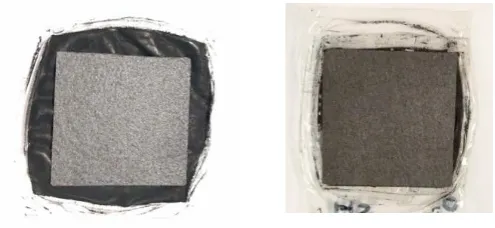
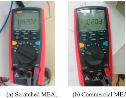
Two MEAs are finally manufactured as shown in Fig. 3. The first one has a larger catalyst area. Because the pressure in the Hot presser is supposed to be 50bar. But the Hot presser in the campus can only work with a minimum pressure of 200bar. However, under such a high pressure, the membrane area and the catalyst area are obviously increased because of the size expansion. To avoid have over-sized catalyst area, some catalyst in the second MEA is scratched out before it being put into the Hot presser. Thus the second MEA shows a smaller catalyst area. Both MEAs are tested using a PEM fuel cell test and control system. The scratched and unscratched MEA showed voltages of about 0.82V and 0.70V respectively, measured with a digital multimeter. Fig. 4 shows the voltages measured for the scratched MEA and a commercial MEA bought from USA. The commercial MEA showed a voltage of about 1.02V, measured with the digital multimeter. It appears that the commercial MEA is better than both lab made MEAs, and the scratched MEA is better than the unscratched MEA. However, at a voltage of 0.1V, the current density of the commercial MEA, the scratched and unscratched MEA were 0.939A, 0.087A and 0.16A, respectively. Thus this time the commercial MEA is better than both lab made MEAs, but the unscratched MEA showed higher current density than that of the scratched MEA.
[image:5.544.151.399.469.583.2]Fig.5 shows the carbon plate in the test for the both MEAs. The unscratched MEA with larger catalyst area clearly showed that there was much water generated and some water oozed through the bipolar plates. There was no water shown for the scratched MEA and the commercial MEA. Usually there is not much water generated in a single cell test, so it is quite surprising and interesting to see so much water came out. A MEA with more catalyst can generate higher current density. But it is not clear why the two lab made MEAs have different performance. Actually the areas outside the gas diffusion layers are sealed out by sealing rings. Thus the catalyst located at the region outside the gas diffusion layers should not have effect on the cell performance. One possible reason could be the direct contact of the catalyst to the reaction gases due to a possible gap between the sealing rings and the unscratched MEA, or too much catalyst were removed thus scratched MEA has less amount of catalyst under the gas diffusion layers.
Fig. 3. Two MEAs produced. (a) Unscratched MEA (b) Scratched MEA
4. Conclusion
A practical and low-cost approach to build MEAs in lab using decal transfer technique is described and verified. Two MEAs manufactured showed voltages of about 0.82V and 0.70V respectively, measured with a digital multimeter, which are lower than that of the commercial MEA. It is found that the unscratched MEA with more catalyst has a lower voltage, but can generate higher current density and much water.
6 Sichang Yang, Xinyu Zhang, Bo Wang, Hanzhe Huang, Zirui Zhao, Xinyuan Wang, Kaili Yu, et el. / Energy Procedia 00 (2018) 000–000
(a) Scratched MEA; (b) Commercial MEA
Fig. 4.Voltages measured for the scratched and a commercial MEA bought from USA
Fig. 5. The carbon plate in the test (a) Uncratched MEA; (b) Scratched MEA
Acknowledgements
The authors acknowledge the financial support from the International Doctoral Innovation Centre, Ningbo Education Bureau, Ningbo Science and Technology Bureau, and the University of Nottingham. This work was also supported by the UK Engineering and Physical Sciences Research Council [grant numbers EP/G037345/1 and EP/L016362/1], Faculty of Science and Engineering at University of Nottingham Ningbo China [SRG code 01.03.05.04.2015.02.001], Ningbo Natural Science Foundation Program [project code 2013A610107] and Ningbo Science and Technology Bureau Technology Innovation Team (Grant No. 2016B10010).
.
References
[1] Tian T, Zheng J, Ma J. PEM FC membrane electrode assembly fabrication and improvement strategies.Chem Ind Eng Prog 2013; 32 (9) p. 2077-2084.
[2] Hurley P. Build your own fuel cells. Wheelock VT USA: Wheelock Mountain Publications; 2002 [3] Hephas energy Co., Ltd. Introduction to MEA Manufacturing process.
[4] Xia CY, Zhuang L, Lu JT. Nafion Emulsion Method for Fuel Cell Membrane-Electrode-Assembly Preparation.Electrochemistry 2005; 11
Sichang Yang et al. / Energy Procedia 145 (2018) 458–463 463 Sichang Yang, Xinyu Zhang, Bo Wang, Hanzhe Huang, Zirui Zhao, Xinyuan Wang, Kaili Yu, et el. / Energy Procedia 00 (2018) 000–000 5
90 oC to heat the fluid inside for 1 hour.
• Put the MEA membrane into the vacuum oven, dry out the membrane for 15 minute at a temperature about 60 oC, and then put the 3-layer MEA membrane into a dry plastic bag.
• Settle two gas diffusion layers at both side of the 3-layers MEA membrane, a 5-layers MEA membrane is done.
3. Result and Test
Two MEAs are finally manufactured as shown in Fig. 3. The first one has a larger catalyst area. Because the pressure in the Hot presser is supposed to be 50bar. But the Hot presser in the campus can only work with a minimum pressure of 200bar. However, under such a high pressure, the membrane area and the catalyst area are obviously increased because of the size expansion. To avoid have over-sized catalyst area, some catalyst in the second MEA is scratched out before it being put into the Hot presser. Thus the second MEA shows a smaller catalyst area. Both MEAs are tested using a PEM fuel cell test and control system. The scratched and unscratched MEA showed voltages of about 0.82V and 0.70V respectively, measured with a digital multimeter. Fig. 4 shows the voltages measured for the scratched MEA and a commercial MEA bought from USA. The commercial MEA showed a voltage of about 1.02V, measured with the digital multimeter. It appears that the commercial MEA is better than both lab made MEAs, and the scratched MEA is better than the unscratched MEA. However, at a voltage of 0.1V, the current density of the commercial MEA, the scratched and unscratched MEA were 0.939A, 0.087A and 0.16A, respectively. Thus this time the commercial MEA is better than both lab made MEAs, but the unscratched MEA showed higher current density than that of the scratched MEA.
Fig.5 shows the carbon plate in the test for the both MEAs. The unscratched MEA with larger catalyst area clearly showed that there was much water generated and some water oozed through the bipolar plates. There was no water shown for the scratched MEA and the commercial MEA. Usually there is not much water generated in a single cell test, so it is quite surprising and interesting to see so much water came out. A MEA with more catalyst can generate higher current density. But it is not clear why the two lab made MEAs have different performance. Actually the areas outside the gas diffusion layers are sealed out by sealing rings. Thus the catalyst located at the region outside the gas diffusion layers should not have effect on the cell performance. One possible reason could be the direct contact of the catalyst to the reaction gases due to a possible gap between the sealing rings and the unscratched MEA, or too much catalyst were removed thus scratched MEA has less amount of catalyst under the gas diffusion layers.
Fig. 3. Two MEAs produced. (a) Unscratched MEA (b) Scratched MEA
4. Conclusion
A practical and low-cost approach to build MEAs in lab using decal transfer technique is described and verified. Two MEAs manufactured showed voltages of about 0.82V and 0.70V respectively, measured with a digital multimeter, which are lower than that of the commercial MEA. It is found that the unscratched MEA with more catalyst has a lower voltage, but can generate higher current density and much water.
6 Sichang Yang, Xinyu Zhang, Bo Wang, Hanzhe Huang, Zirui Zhao, Xinyuan Wang, Kaili Yu, et el. / Energy Procedia 00 (2018) 000–000
[image:6.544.171.372.74.231.2](a) Scratched MEA; (b) Commercial MEA
[image:6.544.123.404.273.412.2]Fig. 4.Voltages measured for the scratched and a commercial MEA bought from USA
Fig. 5. The carbon plate in the test (a) Uncratched MEA; (b) Scratched MEA
Acknowledgements
The authors acknowledge the financial support from the International Doctoral Innovation Centre, Ningbo Education Bureau, Ningbo Science and Technology Bureau, and the University of Nottingham. This work was also supported by the UK Engineering and Physical Sciences Research Council [grant numbers EP/G037345/1 and EP/L016362/1], Faculty of Science and Engineering at University of Nottingham Ningbo China [SRG code 01.03.05.04.2015.02.001], Ningbo Natural Science Foundation Program [project code 2013A610107] and Ningbo Science and Technology Bureau Technology Innovation Team (Grant No. 2016B10010).
.
References
[1] Tian T, Zheng J, Ma J. PEM FC membrane electrode assembly fabrication and improvement strategies.Chem Ind Eng Prog 2013; 32 (9) p. 2077-2084.
[2] Hurley P. Build your own fuel cells. Wheelock VT USA: Wheelock Mountain Publications; 2002 [3] Hephas energy Co., Ltd. Introduction to MEA Manufacturing process.
[4] Xia CY, Zhuang L, Lu JT. Nafion Emulsion Method for Fuel Cell Membrane-Electrode-Assembly Preparation.Electrochemistry 2005; 11