ISSN Online: 1947-3826 ISSN Print: 1949-2421
DOI: 10.4236/cn.2017.93013 Aug. 18, 2017 179 Communications and Network
A Destination Based Routing Protocol for
Context Based Clusters in VANET
Vivek Sethi, Narottam Chand
Department of Computer Science and Engineering, National Institute of Technology Hamirpur, Hamirpur, India
Abstract
Today, vehicular ad-hoc network (VANET) is a hot research topic due to its many applications like collision avoidance, congestion road notification, park-ing lot availability, road-side business advertisements, etc. All these
applica-tions have hard delay constraints i.e. the messages should reach the target
lo-cation within certain time limits. So, there must be efficient routing in VANET which meets these delay constraints. In this paper, two techniques are pro-posed to minimize the data traffic and delay in VANET. Firstly, a context based clustering is proposed which takes into consideration various parame-ters in cluster formation-location of vehicle, direction of vehicle, velocity of
vehicle, interest list of vehicle [1] and destination of vehicle. Secondly, a
des-tination based routing protocol is proposed for these context based clusters for efficient inter-cluster communication.
Keywords
Context-Awareness, Cluster Stability, Optimization, Destination Based Routing
1. Introduction
Vehicular ad-hoc network is a special type of mobile ad-hoc network (MANET) which has some unique features like high and predictable mobility, frequent disconnections in network, geographical based routing, hard delay constraints, etc. Due to these features, the routing protocols of MANETs are not suitable for VANETs. A routing protocol in VANET should meet the delay constraints as well as reduce the overall traffic in the network.
In this paper, two solutions are proposed for efficient communication among vehicles in VANET. Firstly, a stable context based clustering mechanism is pro-posed which takes into consideration following parameters in cluster
forma-How to cite this paper: Sethi, V. and Chand, N. (2017) A Destination Based Routing Pro- tocol for Context Based Clusters in VANET. Communications and Network, 9, 179-191. https://doi.org/10.4236/cn.2017.93013
Received: July 18, 2017 Accepted: August 15, 2017 Published: August 18, 2017
Copyright © 2017 by authors and Scientific Research Publishing Inc. This work is licensed under the Creative Commons Attribution International License (CC BY 4.0).
DOI: 10.4236/cn.2017.93013 180 Communications and Network
tion-location of vehicle, direction of vehicle, velocity of vehicle, interest list of
vehicle [1] and destination of vehicle. By this context based clustering, every
cluster has some interests like interest in parking information, accident notifica-tions, congestion information, etc. When a CH receives a message, it checks whether the vehicles inside the cluster are interested in the message or not. If the vehicles inside the cluster are interested then CH will forward the message to the cluster members. Otherwise, the message will be forwarded to the next CH
without propagating the message inside the cluster [2][3]. This will reduce the
irrelevant information propagation in the network.
Secondly, a destination based routing protocol is proposed for these context based clusters in VANET for efficient inter-cluster communication. In context based clustering, we use destinations of vehicles in cluster formation due to which every cluster has some destination which is determined from the destina-tions of the vehicles within the cluster. When a cluster head needs to forward the message, it must select the optimal cluster heads in its neighborhood to carry the message. A cluster head selects the optimal neighbor cluster heads based on two parameters-direction of neighbor cluster heads and destination of neighbor cluster heads. When a cluster head gets a message, it first computes the direction of transmission (DT) of a message from its position coordinates and target loca-tion (TL) of a message. Then it compares the DT of a message with the direc-tions of neighbor cluster heads using cosine similarity formula as discussed in Section 5. It also compares the TL of a message with the destinations of neighbor cluster heads. The neighbor cluster head whose direction is similar to DT of a message and whose destination is closest to the TL of a message is selected for carrying the message towards the target of a message. This next forwarding node selection is done by calculating a FE (Forward Eligibility) metric. The neighbor node with maximum FE metric will be elected as next forwarding node.
The rest of the paper is organized as follows. In Section 2, various existing routing techniques in VANET are discussed. In Section 3, context based cluster-ing is described. Cluster head selection is illustrated in Section 4. Section 5 de-scribes the proposed destination based routing for context based clusters. Test-ing results are discussed in Section 6. Finally, Section 7 includes the conclusion.
2. Relative Work
There are many routing techniques which were proposed previously, the most common routing protocols used in VANET are as follows:
1) Greedy Perimeter Stateless Routing (GPSR): In [4], authors proposed
loca-DOI: 10.4236/cn.2017.93013 181 Communications and Network
tion is selected as the next optimal node for carrying the message [4]. When the
GPSR sticks due to local minima, it routes the message along the perimeter of the region.
2) Diagonal Intersection Based Routing (DIR): DIR is also a geographical based routing protocol. In DIR, a series of diagonal intersections are constructed between source and destination and routing is done through these intersections
[5]. Source node sends the data packet to the first intersection, then second
in-tersection and so on, until last inin-tersection and finally it is forwarded to the tar-get location. Between two intersections, there may be many sub-paths exist. The sub-path with minimum delay is selected for forwarding the message.
3) Cluster Based Routing (CBR): In CBR, when a source node wants to send a message to the target location (TL), it doesn’t discover the route but forward the message to the neighbor cluster head whose geographical position has minimal
angle with the data packet’s destination [6]. This policy is repeated until the
message arrives at the TL.
4) Cluster Based Directional Routing: In cluster based directional routing, a source node forwards the message to the neighbor cluster head whose moving
direction is similar to that of transmission direction of a message [7].
Transmis-sion direction of the message is computed by a node using its position coordi-nates and target location of the message.
The previous routing protocols have many drawbacks. GPSR and CBR do not consider the direction of the neighbor nodes while selecting the next optimal forwarding node which may be inefficient. Cluster Based Directional Routing does not consider destinations of neighboring nodes while selecting the next forwarding node. DIR causes additional overhead in making routing decisions. By taking into consideration all these drawbacks, a destination based routing al-gorithm is proposed.
3. Context Based Cluster Formation
In context based clustering, vehicles are grouped to form clusters based on five parameters as follows:
Location: Each vehicle can determine its current location by using a loca-tion-aware device known as global positioning system (GPS). This GPS device supplies information to on-board unit (OBU), which determines its current
loca-tion. The location of a vehicle is determined in the form of (Locationx, Locationy)
pair. For vehicles to be in the same cluster, the distance between the vehicles should be minimum.
Direction: The direction of a vehicle is determined by calculating the differ-ence between last two locations collected by a GPS device. It is represented in the
form of (Directionv). For vehicles to be in the same cluster, the directions of
ve-hicles should be similar.
Velocity: The velocity of a vehicle is represented in the form of (Velocityv) and
differ-DOI: 10.4236/cn.2017.93013 182 Communications and Network
ence should be minimum.
Destination: The destination coordinates can be determined by the location
aware device and is represented in the form of (Destinationx, Destinationy). There
can be two choices to determine the destination of a vehicle-one is final destina-tion (FD) which is determined by GPS and other is relative destinadestina-tion (RD) which is determined with respect to some reference point. For vehicles to be in the same cluster, the distance between the destinations of vehicles should be minimum.
Interest list: Every vehicle has some interests [1]. Some vehicles are interested
in parking information, some vehicles are interested in nearby restaurant infor-mation, some vehicles are only interested in accident and congestion inforinfor-mation, etc. To represent the interests of a vehicle, a vector is used. Every vehicle “k” maintains a vector of interests [1] in the form of:
(
1, 2, 3, ,)
I n
PK = PK PK PK PK
Here, PKI is a value (expressed as a fraction or percentage) which indicates
how much the user is interested in topic “I”. e.g. [1, 0, 1] may indicate that a ve-hicle is interested in parking and congestion information but has no interest in accident information. For vehicles to be in the same cluster, the interest lists of vehicles should be similar. The similarity between the interest lists of vehicles is
determined by cosine similarity formula [1].
Based on above parameters, groups among the vehicles are formed. Each group has a group representative known as cluster head (CH). The CH will maintain the interests of a vehicle. When a CH receives some message, it first checks whether the vehicles inside the cluster are interested in the message or not. If the vehicles inside the cluster are interested then CH will forward the message to all the members of the cluster. Otherwise, the message will be forwarded to the next cluster head without propagating the message inside the cluster. This will reduce
the irrelevant network transmissions within the cluster [2].
4. Cluster Head Selection
For optimal cluster head selection, a weighted cluster head selection algorithm is proposed in which every node computes a weight based on certain parameters
and the node with maximum weight will be elected as the cluster head [8][9].
Cluster head selection involves following steps:
1) In the first step, each vehicle obtains its clustering parameters-location, di-rection, velocity, destination and interest list from its onboard unit.
2) In the second step, each vehicle identifies its neighboring vehicles whose direction is similar to it.
3) After identifying its neighboring vehicles with similar direction, each ve-hicle sends/receive its clustering parameters to/from its neighbors.
DOI: 10.4236/cn.2017.93013 183 Communications and Network
(IC). Interest list compatibility (IC) is computed using cosine similarity formula
[1]. e.g. IC between vehicle “X” and vehicle “Y” is calculated by using Equation
(1): 1 , 2 2 1 1 n k k k
X Y n n
k k k k px py IC px py = = = =
∑
∑
∑
(1)5) After maintaining a list for each neighboring vehicle, each vehicle calculates its cluster head eligibility (CHE) value using Equation (2):
k k
k k k
AC CHE
AD AV ARD
= (2)
Here, ADk specifies the average distance between vehicle “k” and each of its
neighbor “j”[1][10]. In order to increase CHE value of a vehicle, this parameter
ADk should be minimum. The parameter ADk is computed using Equation (3).
(
) (
2)
2j k j k
J k
x x y y
AD
N
− + −
=
∑
(3)Here
(
x yk, k)
,(
x yj, j)
represents position coordinates of vehicles “k” and“j” respectively and “N” is the number of neighbors.
AVk is the average of the contrasts between velocity of the vehicle “k” and
each of its neighbor “j” [1][10][11]. It is calculated by using Equation (4). This
parameter should also be minimum. It is calculated as:
k j J k v v AV N −
=
∑
(4)Here vk, vj represents speeds of vehicles “k” and “j” respectively.
ACk is the average of the interest compatibilities between vehicle “i” and each
of its neighbor “j” [1]. It is calculated by using Equation (5).
kj k
IC AC
N
= (5)
In order to maximize CHE value, this parameter should be maximized.
ARDk is the average of the distances between relative destination of vehicle
“k” and each of its neighbor “j” [12]. It is calculated by using Equation (6).
(
) (
2)
2j k j k
J k
x x y y
ARD
N
− + −
=
∑
(6)Here
(
x yj, j)
and(
x yk, k)
represents coordinates of relative destinationsof vehicles “k” and “j”. In order to maximize CHE value, this parameter should also be minimized.
6) After calculating CHE value, each vehicle sends/receives CHE value to/ from its neighbors.
DOI: 10.4236/cn.2017.93013 184 Communications and Network
that contains all the ids of the vehicles inside the cluster. In case of multi-hop
clustering [13], sub-cluster heads are also formed as discussed later. For every
topic of interest, if more than 50% of the vehicles in the cluster are interested in the topic then that topic becomes the topic of interest of the cluster.
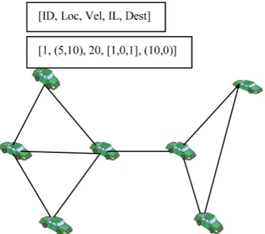
The illustration of cluster head selection and cluster formation is as follows: First, every vehicle obtains its clustering parameters from their on-board units
(OBU) as shown in Figure 1.
Here, IL is represented in the form of a vector as [1, 0, 1] which may indicate that the vehicle is interested in traffic congestion and accident information but not interested in parking information.
In second step, each vehicle exchange parameters with their neighbors and calculate the interest list compatibility (IC) for each of its neighbor using Equa-tion (1). After obtaining the parameters from each of its neighbor, the vehicle
calculates its CHE value using Equation (2). In Figure 2, the CHE value
calcu-lated by each vehicle is shown.
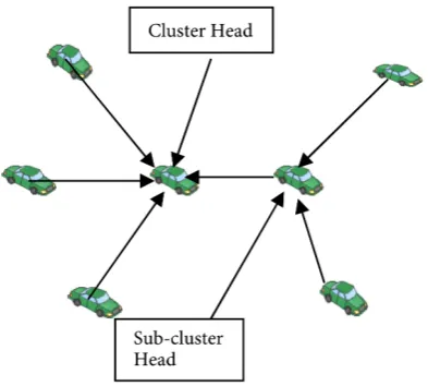
The vehicle with highest CHE value will be elected as a Cluster Head. In
[image:6.595.281.469.340.506.2]Fig-ure 3, the vehicle with highest CHE value of 3.03 is shown as a cluster head and
Figure 1. Sample parameters obtained by a vehicle.
[image:6.595.211.540.541.712.2]DOI: 10.4236/cn.2017.93013 185 Communications and Network
Figure 3. Cluster head selection.
the vehicle with CHE value of 2.84 is shown as a sub-cluster head.
5. Proposed Routing Protocol for VANET
In previous Sections 3 and 4, we make clusters based on five parameters-location of vehicle, direction of vehicle, velocity of vehicle, interest list of vehicle and tination of vehicle. As a result of this, every cluster has some direction and des-tination. The destination of a cluster is assumed to be the destination of the cluster head. The proposed destination based routing protocol considers two parameters-direction of cluster head and destination of cluster head in order to select the next forwarding cluster head node.
Every message has some target location TL and direction of transmission DT
[7]. When a node “k” having position coordinates
(
x yk, k)
receives a messagewhose target location is
(
xtl,ytl)
, the direction of transmission DT vector iscomputed using Equation (7).
(
xk x ytl, k ytl)
= − −
DT (7)
And, every cluster head “h” has a velocity vector which can be represented as shown in Equation (8).
ˆ ˆ
h=v ih +v jh
V (8)
The direction of transmission DT is said to be similar to the direction of
cluster head “h” if their cosine similarity is greater than 0. The similarity
be-tween DT and Vh is computed using Equation (9).
Similarity cos h
h
h DT V
θ= ⋅
= DT V (9)
Also, every cluster head “h” has some destination which is represented as
(
DestX DestYh, h)
. The distance between the target location(
xtl,ytl)
and thedestination of cluster head is calculated by using Equation (10).
(
) (
2)
2h tl h tl h
D x DestX y DestY
DOI: 10.4236/cn.2017.93013 186 Communications and Network
5.1. Routing Procedure
Following are the steps of our proposed destination based routing protocol: 1) When a source node “s” wants to send a message to the destination node “d”, it first forwards the message containing target location TL
(
xtl,ytl)
to itscluster head “k”.
2) The cluster head “k” then checks whether the TL is inside the cluster or not. If the cluster head “k” finds the TL inside the cluster, it forwards the message to TL. Otherwise, it selects the next neighbor cluster head “h” for forwarding the message.
3) In order to select the next forwarding cluster head node, a cluster head “k” uses the destinations and directions of its neighbor cluster heads. First, it calcu-lates the direction of transmission of a message DT using Equation (7). Then it
calculates Similarityh using Equation (9) for each neighbor cluster head node
“h” having velocity Vh. Then it calculates the distance between the target
loca-tion and destinaloca-tion ∆Dh for each neighbor cluster head node “h” using
Equa-tion (10).
4) After calculating Similarityh and ∆Dh for each neighbor cluster head
node “h”, a cluster head node “k” calculates the following metric FE (forwarding eligibility) for each neighbor cluster head node “h”:
Similarity 100 h
h F
D
E ×
∆
= (11)
5) The neighbor cluster head node whose FE value is maximum is selected as the next forwarding cluster head node.
6) Again, the next forwarding cluster head node checks whether the target lo-cation TL is inside the cluster or not. If it finds the TL inside the cluster, it for-wards the message to TL. Otherwise, it again selects the next forwarding cluster head node by using FE and the process is repeated.
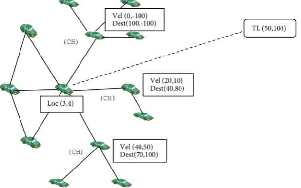
[image:8.595.222.531.513.706.2]In Figure 4, the node “k” has location (3, 4) and it has three neighbor cluster
DOI: 10.4236/cn.2017.93013 187 Communications and Network
head node. First neighbor cluster head node has velocity (20, 10) and destination (40, 80). Second cluster head node has velocity (40, 50) and destination (70, 100). Third cluster head node has velocity (0, −100) and destination (100, −100). The target location has coordinates (50, 100).
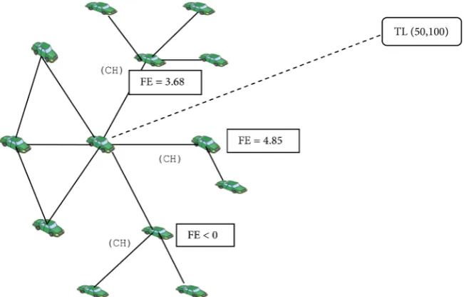
Using these sample values, the node “k” computes FE metric for each of its
neighbor as shown in Figure 5.
The node with FE value of 4.85 will be selected as the next forwarding cluster head node. This node will be the optimal next forwarding node. In contrast, the other routing techniques may choose the next forwarding node (e.g. node with FE value 3.68) based on their current position which may not be always efficient.
5.2. Flow Chart for Routing Procedure
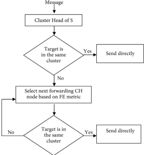
The flow chart for our proposed routing procedure is shown in Figure 6. In
Figure 6, when a source node “S” gets a message, it forwards the message to its cluster head. The cluster head first checks whether the target location is within the cluster or not. If yes, it forwards the message to the target location. Other-wise, it selects the next forwarding CH node based on the FE metric. The next forwarding CH node again checks the availability of target location within its cluster. If it doesn’t find the target location, it again selects the next forwarding CH node and the process is repeated until the message reaches its target loca-tion.
6. Testing Results
[image:9.595.212.538.494.702.2]To test the performance of our proposed destination based routing scheme in context based clustered environment, two types of simulators are used-Traffic Simulator which simulates the mobility of vehicles across the streets and Net-work Simulator which simulates the netNet-work among the vehicles. SUMO (Simu-
DOI: 10.4236/cn.2017.93013 188 Communications and Network
Figure 6. Flow chart for routing procedure.
lation of UrbanMobility) is the most popular traffic simulator used in VANET. There are many features of SUMO which makes it a very useful traffic simulator such as multi-lane streets with lane changing, different vehicle types, representing networks with many streets, coupling with network simulators (ns2), etc. For network simulation, ns2 is used. The output of SUMO is a mobility trace which acts as a input to the network simulator ns2.
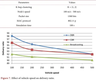
The simulation parameters and their values used are shown in Table 1.
In Simulation, the factors like loss %, delivery ratio, delivery delay, etc. in our proposed approach are compared with that in cluster based routing (CBR) scheme as well as with traditional broadcasting scheme.
In Figure 7, the delivery ratio is calculated over different speeds of vehicles in destination based routing, cluster based routing and broadcast scheme. It is found that delivery ratio decreases as the speed of vehicles increases. The deli-very ratio is checked with three set of speeds-100 m/s, 200 m/s and 500 m/s.
In Figure 8, the loss percentage is calculated over varying speed of vehicles (100 m/s - 500 m/s) for destination based routing, cluster based routing and broadcasting. It is found that loss % increases as the speed of vehicles increases.
In Figure 9, delivery delay of packets is calculated over varying speed of ve-hicles. It is found that the delay increases as the speed of vehicles increases. This is due to the fact that the link between the nodes changes as the speed of vehicles increases.
DOI: 10.4236/cn.2017.93013 189 Communications and Network
Table 1. Simulation parameters.
Parameters Values
K-hop clustering K = {1, 2}
Node’s speed 100 m/s - 500 m/s
Packet size 1500 bits
MAC protocol 802.11 p
Simulation time 100 s
[image:11.595.217.534.375.518.2]Figure 7. Effect of vehicle speed on delivery ratio.
Figure 8. Effect of vehicle speed on loss percentage.
[image:11.595.217.532.550.707.2]DOI: 10.4236/cn.2017.93013 190 Communications and Network
broadcast scheme in terms of delivery ratio, packet drops, delivery delay, etc. This is due to the fact that our proposed routing technique always chooses an
optimal next forwarding node based on the FE metric as shown in Figure 5.
7. Conclusion
Many clusters based routing techniques like CBR make use of current location of a node and its neighbor nodes in order to determine the next forwarding node. This may not be the optimal next forwarding node selection as the node may be currently closer or at small angle with the target location but it may change its direction and move away from the target location in future. So, we must take the direction of movement of a node as well as destination of a node in order to se-lect the next forwarding node. This will increase the delivery ratio and reduce the overall delay to route the message from source node to destination node.
References
[1] Tal, I. and Muntean, G.M. (2012) User-Oriented Cluster-Based Solution for Multi-media Content Delivery over VANETs. IEEE International Symposium on Broad-band Multimedia Systems & Broadcasting, 11, 1-5.
https://doi.org/10.1109/BMSB.2012.6264290
[2] Paridel, K., Mantadelis, T., Yasar, A.U.H., Preuveneers, D., J., Vanrompay, G.Y. and Berbers, Y. (2012) Analyzing the Efficiency of Context-Based Grouping on Colla-boration in VANETs with Large Scale Simulation. Springer-Verlag, Berlin.
[3] Aswathy, M.C. and Tripti, C. (2012) A Cluster Based Enhancement to AODV for Inter-Vehicular Communication in VANET. International Journal of Grid Compu-ting & Applications, 3, 41-50. https://doi.org/10.5121/ijgca.2012.3304
[4] Karp, B. and Kung, H.T. (2000) GPSR: Greedy Perimeter Stateless Routing for Wireless Networks. Proceedings of the 6th Annual ACM/IEEE International
Con-ference on Mobile Computing and Networking, Boston, MA, 6-11 August 2000,
243-254.
[5] Chen, Y.S., Lin, Y.W. and Pan, C.Y. (2011) DIR: Diagonal-Intersection-Based Rout- ing Protocol for Vehicular Ad Hoc Networks. Telecommunication Systems, 46, 299-316. https://doi.org/10.1007/s11235-010-9294-2
[6] Luo, Y.Y., Zhang, W. and Hu, Y.Q. (2010) A New Cluster Based Routing Protocol for VANET. Proceedings of International Conference on Network Security,
Wire-less Communications and Trusted Computing, Wuhan, 24-25 April 2010, 176-180.
https://doi.org/10.1109/NSWCTC.2010.48
[7] Song, T., Xia, W.W., Song, T.C. and Shen, L.F. (2010) A Cluster-Based Directional Routing Protocol in VANET. Proceedings of 12th IEEE International Conference
on Communication Technology, Nanjing, 11-14 November 2010, 1172-1175.
[8] Matthias, R., Andronache, B.A. and Rothkugel, S. (2010) WACA: A Hierarchical Weighted Clustering Algorithm Optimized for Mobile Hybrid Networks. Cluster Computing,5, 193-204.
[9] Hadded, M., Muhlethaler, P., Zagrouba, R., Laouiti, A. and Saidane, L.A. (2015) Using Road IDs to Enhance Clustering in Vehicular Ad Hoc Networks. Proceedings of International Wireless Communications & Mobile Computing Conference, Du-brovnik, 24-28 August 2015, Article ID: 01211450.
DOI: 10.4236/cn.2017.93013 191 Communications and Network [10] Shea, C., Hassanabadi, B. and Valaee, S. (2009) Mobility-Based Clustering in VA-NETs Using Affinity Propagation. Proceedings of the 28th IEEE Conference on
Global Telecommunications, Honolulu, 30 November-4 December 2009, 4500-
4505.
[11] Arkian, H.R., Atani, R.E., Pourkhalili, A. and Kamali, S. (2015) A Stable Clustering Scheme Based on Adaptive Multiple Metric in Vehicular Ad-Hoc Networks. Journal of Information Science and Engineering, 31, 361-386.
[12] Morales, M.M.C., Haw, R., Cho, E.J. and Hong, C.S. (2012) An Adaptable Destina-tion-Based Dissemination Algorithm Using a Publish/Subscribe Model in Vehicular Networks. Journal of Computing Science and Engineering, 6, 227-242.
https://doi.org/10.5626/JCSE.2012.6.3.227
[13] Chen, Y.Z., Fang, M.Y., Shi, S., Guo, W.Z. and Zheng, X.H. (2015) Distributed Mul-ti-Hop Clustering Algorithm for VANETs Based on Neighborhood Follow. EURA
-SIP Journal on Wireless Communications and Networking, 2015, 1-12.
https://doi.org/10.1186/s13638-015-0327-0
Submit or recommend next manuscript to SCIRP and we will provide best service for you:
Accepting pre-submission inquiries through Email, Facebook, LinkedIn, Twitter, etc. A wide selection of journals (inclusive of 9 subjects, more than 200 journals)
Providing 24-hour high-quality service User-friendly online submission system Fair and swift peer-review system
Efficient typesetting and proofreading procedure
Display of the result of downloads and visits, as well as the number of cited articles Maximum dissemination of your research work
Submit your manuscript at: http://papersubmission.scirp.org/