Bridge De
fl
ection Measurement Using Digital Image Correlation
with Camera Movement Correction
Satoru Yoneyama and Hiroki Ueda
Department of Mechanical Engineering, Aoyama Gakuin University, Sagamihara 229-8558, Japan
When displacement measurement by digital image correlation is performed in outside for the inspection of real structures, the position and the direction of a camera are often changed slightly because of wind, oscillations and the lack of stability of ground. In order to realize the bridge deflection measurement by digital image correlation, a method for correcting the effect of camera movement is proposed in this study. The relationship between images before and after the camera movement is described by an equation of perspective transformation. The unknown coefficients of the equation are determined from undeformed regions of the images. Then, the effect of the camera movement is eliminated by using the perspective transformation. The effectiveness is validated by applying the proposed method to the rigid body rotation and translation measurement of a planar specimen, the deflection measurement of a wide-flange beam, and the bridge deflection measurement. Results show that the effect of the camera movement can be corrected by the proposed method. It is emphasized that noncontact displacement measurement is possible by simple and easy procedure with digital image correlation for the structural evaluation of infrastructures.
[doi:10.2320/matertrans.I-M2011843]
(Received November 10, 2009; Accepted March 11, 2011; Published December 28, 2011)
Keywords: deflection, bridge, girder, digital image correlation, camera movement
1. Introduction
For the structural evaluation of bridges, various tests are usually performed to investigate the structural properties such as natural frequencies, dynamic responses, and strains.13)
One of these properties is vertical deflection of bridge girders. Several different types of transducers and sensors can be used to measure the deflection.46)However, most of these sensors
require the access to measurement location under bridges. Therefore, it would be required to interrupt traffic under bridges for the setup of these transducers. In addition, the installation of these transducers is time-consuming. There-fore, various techniques for the noncontact measurement of bridge deflection have been studied.710)On the other hand, noncontact measurement of bridge deflection by a digital image correlation technique is possible as demonstrated by one author previously.11,12) Digital image correlation can obtain the surface deformation by comparing digital images of undeformed and deformed configurations.13)Since digital image correlation technique does not need a complicated optical system, the measurement can be performed simply and easily. Thus, a lot of applications of this method to various problems can be found in the field of experimental solid mechanics.1416)
In digital image correlation, the camera position must not be changed during the measurement because this technique extracts displacements from digital images directly. When the measurement is performed in outside for the inspection of real structures, however, the position and the direction of a camera are often changed slightly because of wind, oscillations and the lack of stability of ground. In this case, the displacement cannot be measured because the effect of the camera movement is included in the measured displacement. In order to realize the bridge deflection measurement by digital image correlation, a method for correcting the effect of camera movement is proposed in this study. The relationship between images before and after the camera movement is described by an equation of perspective transformation. The
unknown coefficients of the equation are determined from undeformed regions of the images. Then, the effect of the camera movement is eliminated by using the perspective transformation. The effectiveness is validated by applying the proposed method to the rigid body rotation and translation measurement of a planar specimen and the deflection measurement of a wide-flange beam. In addition, the effectiveness is also demonstrated by applying the proposed method to the deflection measurement of a real bridge girder. Results show that the effect of the camera movement can be corrected by the proposed method. It is emphasized that noncontact displacement measurement is possible by simple and easy procedure with digital image correlation for the structural evaluation of infrastructures.
2. Method for Correcting the Effect of Camera Movement
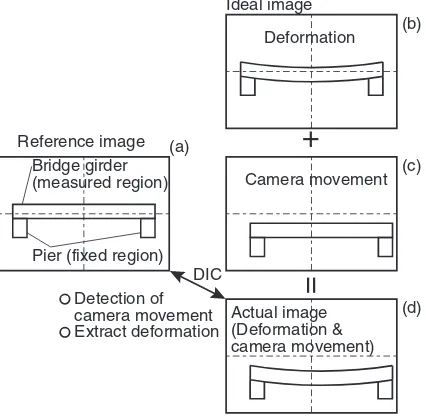
Figure 1 shows the outline of the proposed method. An undeformed image (reference image) of an object such as bridge is recorded as shown in Fig. 1(a). The object is deformed by a load as shown in Fig. 1(b). When the camera is moved before acquiring an image of the deformed object, the image includes information of not only the deformation but also the camera movement, as shown in Fig. 1(d). In the proposed method, the camera movement shown in Fig. 1(c) is detected from the undeformed regions such as piers. Then, the deflection of the measured region such as a girder is obtained by eliminating the effect of the camera movement. Figure 2 shows the geometric relationship between image planes of a camera before and after the camera movement. In this figure, a point P positioned at (x,y,z) on an object is projected at P1on an image plane. The point P1is located at
(u,v) on the image plane. The same point P on the object is imaged at the point P2at (u¤,v¤) after the camera movement.
In this case, the relationship between the coordinates (u,v) of the point P1, and (u¤,v¤) of the point P2 is expressed by
perspective transformation as17) Special Issue on APCNDT 2009
u¼a1u0þa2v0þa3
a7u0þa8v0þ1
v¼aa4u0þa5v0þa6 7u0þa8v0þ1
ð1Þ
where a1³a8 are the coefficients that express the camera
movement. Therefore, the coordinate (u¤,v¤) on the image after the camera movement can be corrected to the coordinate (u,v) before the camera movement provided that the coefficients of the equation are known. The coefficients are determined fromfixed reference points that can be considered to be not deformed. Applying digital image correlation technique to thefixed region, the data sets of the coordinates (u,v) and (u¤,v¤) before and after the camera movement are obtained. Then, the coefficients in eq. (1) are determined using the method of linear least-squares. The coordinates of the deformed region such as a girder after the camera movement are then corrected using eq. (1). After that, the actual displacements can be determined.
3. Rigid Body Rotation and Translation Measurement
In order to validate the method described in previous section, rigid body rotation and translation are measured with and without the camera movement. The experimental setup is shown in Fig. 3. A planar specimen, 120 mm in height and 120 mm in width, is mounted on a rotation and translation stage. The resolution of the stage is 4.0©10¹3 degrees for
rotation and 1.0©10¹3mm for translation. Two additional
planar objects are placed at the either side of the specimen. These planar objects are used asfixed reference regions for determining the coefficients in eq. (1). The surfaces both of the specimen and thefixed regions are sprayed by black and white paint to create random pattern. Then, the specimen surface and the fixed regions are observed by a mono-chromatic CCD camera (1280©1024 pixels and 8 bits). The specimen is moved 1 mm to left side and rotated 2 degrees in counterclockwise direction. The images of the specimen before and after the movement of the specimen are acquired to obtain the displacement without the camera movement. Next, the camera is moved 8 mm to right side and rotated about 0.6 degrees to observe the same region of the specimen surface and thefixed object surface as shown in Fig. 3. Then, the displacements with and without camera movement, and the corrected displacement by the proposed method are obtained.
Figure 4 shows the images obtained in this experiment. The random pattern created by spray painting for obtaining the correlation between two images is observed on both the measured and thefixed regions. Thex-directional component
uxof the displacement obtained by digital image correlation is plotted in Fig. 5. In thisfigure, the displacement without the camera movement, that is, the actual displacement is also shown. The displacement distribution obtained when the camera is moved is different from the actual displacement by the effect of the camera movement. Figure 6 shows the difference ux¹uxact between the displacements with and
without camera movement. The difference, that is, the error
Pier (fixed region)
Actual image (Deformation & camera movement)
=
Detection of camera movement Extract deformation DIC (d)Fig. 1 Outline of the proposed method of camera movement correction.
P(x,y,z)
P1(u,v) P2(u’ ,v’ )
O1 O2
Camera movement Image plane Object x y z o
O1, O2:Lens center
Fig. 2 Geometrical relationship between image planes before and after the camera movement.
Translation 1 mm
CCD camera u v w u’ v’ w’ 8 mm 0.6 deg
[image:2.595.315.534.69.284.2] [image:2.595.64.277.73.281.2] [image:2.595.55.282.334.496.2]introduced by the camera movement is about 0.6 mm. Applying the proposed method, the displacement obtained with the camera movement is corrected. The difference
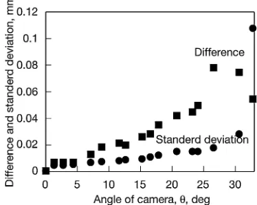
uxcorr¹uxact between the corrected displacement and the actual displacement is also shown in thisfigure. As shown in this figure, the difference about 0.6 mm is corrected to zero. The camera is moved again and the measurement is repeated as shown in Fig. 7. The average value of the difference of the actual and the corrected displacements with respect to the angleªof the camera are shown in Fig. 8. As shown in thisfigure, the difference is less than 0.1 mm even if the angle of the camera is large as 30 degrees. The difference
of 0.1 mm corresponds to the small value of about 0.6 pixels. The results of the rigid body rotation and translation test show that the effect of the camera movement is corrected by the proposed method.
4. Measurement of the Deflection of a Wide-Flange Beam
Experimental tests have been performed to evaluate the applicability of the proposed method to the deflection
(a) (b)
Fig. 4 Images obtained for rigid body rotation and translation test: (a) reference image; (b) image after rotation and translation.
Fig. 5 x-directional displacement distributions obtained with and without camera movement.
Fig. 6 Differences between the displacements with and without camera movement correction and the actual displacement.
θ
CCD camera
Measured region Fixed region Fixed region
7000 mm
Fig. 7 Setup for additional rigid body rotation and translation test.
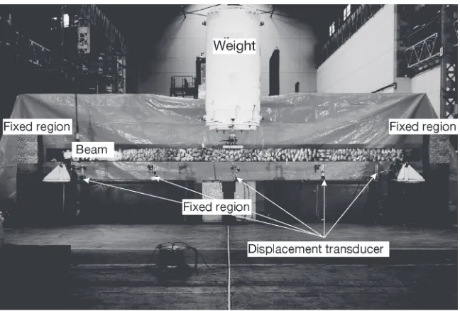
[image:3.595.149.449.70.204.2] [image:3.595.334.519.239.432.2] [image:3.595.49.287.243.397.2] [image:3.595.49.288.444.595.2] [image:3.595.332.519.472.621.2]measurement of large structures. The deflection measurement of a beam under three-point bending is adopted in this experiment as shown in Figs. 9 and 10. A wideflange beam made of SS400 steel, 5000 mm in long, 200 mm in width and 8 mm in thickness, is placed on two supports. The modulus of elasticity and the moment of inertia of the cross-sectional area of the beam are estimated as 210 GPa and 1.60©107mm4,
respectively. Various loads are applied at the middle point of the beam by a weight that is hung by a crane from the ceiling. The load is measured by a load cell placed between the weight and the beam. White colored random pattern is
painted on the surface of the beam. Fixed areas with random pattern are placed on both sides and below the beam to apply the proposed method of the camera movement correction. The images of the beam before and after deformation are recorded by a single-reflex type digital camera (3504©2336 pixels©24 bits). Here, after the undeformed image is recorded, the camera is removed and then placed at almost same position. Therefore, the amount of the camera move-ment is unknown. The deflections of the beam are also measured at the position of 1/4, 1/2 and 3/4 of the length by displacement transducers of the resolution of 0.005 mm.
[image:4.595.113.480.60.345.2]Fig. 9 Schematic diagram of the experimental setup for deflection measurement of wide-flange beam.
[image:4.595.137.461.393.612.2]Applying digital image correlation to these images, the deflection distributions are determined. Figure 11 shows the deflection curve obtained by digital image correlation. Different values of the deflection at the both supports are obtained. The deflection curves in Fig. 11 are corrected by the proposed method. Figure 12 shows the deflection curves after the camera movement correction. In this figure, the deflections corrected by the proposed method agree well with those obtained by the displacement transducers. The results of the beam deflection measurement also show that the effect of the camera movement is corrected by the proposed method.
5. Bridge Deflection Measurement
Thefield study of bridge deflection measurement is carried out for a concrete girder bridge. The length of the bridge is measured as about 20 m. Unlike the bridge load test reported in previous study,12)the deflection under usual load by traffic
is measured. The image before deformation is recorded when there is no traffic on the bridge. The image after deformation is acquired at an instant when a bus passes on the bridge. The deflection without camera movement is obtained from these two images. Then, the camera position is moved slightly to demonstrate the proposed method. After that, the image after deformation with camera movement is obtained when another bus passes on the bridge. A single-reflex type digital camera (3008©2000 pixels©24 bits) is used for measurements.
The photographs of the bridge before and after load are shown in Fig. 13. Thefixed reference regions are both sides
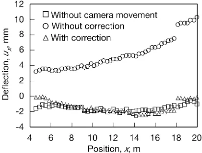
of the bridge as shown in this figure. The measured and corrected deflection distributions of the bridge girder are shown in Fig. 14. The abscissa shows the position that is measured from the left edge of the bridge. Because there is a barrier, the deflection at the left side is not obtained. In this
[image:5.595.66.277.68.211.2]figure, the deflection without the camera movement is also shown for comparison. The reasonable deflection distribution is obtained by correcting the camera movement. In addition, the values of the corrected deflection agree well with the values obtained without the camera movement. The results of the field study show that the bridge deflection can be measured by digital image correlation even if the position of the camera is moved.
[image:5.595.322.531.71.191.2]Fig. 11 Deflection distributions without the camera movement correction.
Fig. 12 Deflection distributions with the camera movement correction.
(a) (b)
Fig. 13 Images of bridge: (a) before load; (b) after load with camera movement.
[image:5.595.133.466.251.380.2] [image:5.595.323.529.420.576.2]digital image correlation. The validity of the proposed method is demonstrated by measuring the rigid body displacements, the deflection of the beam, and the deflection of the bridge. Results show that the effect of the camera movement can be corrected by the proposed method. It is emphasized that noncontact displacement measurement is possible by simple and easy procedure with digital image correlation for the structural evaluation of infrastructures.
Acknowledgment
The part of this work was supported by Hitachi Zosen Corporation and Nichizo Tech Incorporated. Their assistance and cooperation are greatly appreciated.
6) N.-S. Kim and N.-S. Cho:Exp. Mech.44(2004) 433439.
7) D. V. Jáuregui, K. R. White, C. B. Woodward and K. R. Leitch: J. Bridge Eng.8(2003) 212222.
8) C. C. Chang and Y. F. Ji:J. Eng. Mech.133(2007) 656664. 9) J. J. Lee and M. Shinozuka:NDT & E Int.39(2006) 425431. 10) J. J. Lee and M. Shinozuka:Exp. Mech.46(2006) 105114. 11) S. Yoneyama, A. Kitagawa, S. Iwata, K. Tani, K. Kitamura and H.
Kikuta: J. Jpn. Soc. Non-destruct. Inspect.55(2006) 119125. 12) S. Yoneyama, A. Kitagawa, S. Iwata, K. Tani and H. Kikuta: Exp.
Tech.31(2007) 3440.
13) H. A. Bruck, S. R. McNeill, M. A. Sutton and W. H. Peters:Exp. Mech. 29(1989) 261268.
14) G. Murasawa and S. Yoneyama:Mater. Trans.47(2006) 766771. 15) N. Li, M. A. Sutton and X. Li:Exp. Mech.48(2008) 635646. 16) M. S. Kirugulige and H. V. Tippur:Strain45(2009) 108122. 17) M. Takagi and H. Simoda:Handbook of Image Analysis(in Japanese),