TR-124
Functional Requirements for Broadband Residential Gateway
Devices
Issue: 1.0
Notice
The Broadband Forum is a non-profit corporation organized to create guidelines for broadband
network system development and deployment. This Technical Report has been approved by
members of the Forum. This document is not binding on the Broadband Forum, any of its
members, or any developer or service provider. This document is subject to change, but only
with approval of members of the Forum.
This document is provided "as is," with all faults. Any person holding a copyright in this
document, or any portion thereof, disclaims to the fullest extent permitted by law any
representation or warranty, express or implied, including, but not limited to,
(a) any warranty of merchantability, fitness for a particular purpose, non-infringement, or title;
(b) any warranty that the contents of the document are suitable for any purpose, even if that
purpose is known to the copyright holder;
(c) any warranty that the implementation of the contents of the documentation will not infringe
any third party patents, copyrights, trademarks or other rights.
Issue History
Issue Number
Issue Date
Issue Editor
Changes
1.0
December 2006 Jaime Fink, 2Wire
Jack Manbeck, Texas
Instruments
Original
Technical comments or questions about this document should be directed to:
Editor:
Jaime Fink
2Wire
Jack Manbeck
Texas
Instruments
WG Chairs
Greg Bathrick
PMC Sierra
Heather
Kirksey
Motive
Table of Contents
1 Purpose ... 8
2 Scope ... 8
2.1 Definitions... 9
2.2 Abbreviations... 9
2.3 Conventions ... 12
3 References ... 13
4 Residential
Gateway
Requirements ... 18
General Device Requirements ... 18
Design... 18
Device Operation... 19
Networking Protocols... 20
Wide Area Networking (WAN) ... 21
ATM... 21
ATM Multi-PVC ... 22
Connection Establishment... 23
Ethernet OAM ... 23
Bridging... 24
DHCP Client ... 24
PPP Client ... 26
802.1x Client ... 27
Denial of Service Prevention... 28
Quality of Service... 28
Local Area Networking (LAN) ... 30
General LAN Protocols... 30
Private Addressing ... 30
DHCP Server... 31
Naming Services ... 33
NAT/NATP ... 34
Port Forwarding... 34
ALG Functions... 35
IGMP and Multicast in Bridged Configurations ... 37
IGMP and Multicast in Routed Configurations ... 37
Firewall (Basic) ... 39
Firewall (Advanced)... 39
Time of Day Filtering... 41
Content Filtering ... 41
Automated User Diagnostics... 41
Captive Portal with Web Redirection... 41
Management & Diagnostics ... 42
General ... 42
UPnP... 44
UPnP IGD ... 44
Local Management... 44
Remote Management (TR-069) ... 46
Remote Management (Web Browser)... 47
Network Time Client... 47
WAN Interface Modules ... 48
ADSL and ADSL2+... 48
VDSL2 ... 49
xDSL General Requirements ... 50
xDSL INP Values... 50
xDSL Bonding... 51
xDSL Reporting of Physical Layer Issues ... 52
DC Sealing Current ... 52
AC Power Surge Protection ... 53
Ethernet (WAN) ... 53
GPON ... 54
MoCA (WAN)... 55
LAN Interface Modules... 57
Ethernet (LAN) ... 57
Ethernet Switch ... 57
USB (PC)... 57
Wireless: General Access Point Functions... 58
Wireless: 802.11g Access Point ... 60
Wireless: 802.11a Access Point ... 61
Wireless: 802.11h Access Point ... 61
HomePNA (Phoneline/Coax)... 61
MoCA (LAN)... 64
HomePlug AV (LAN) ... 65
Regional Annexes... 66
North American Power and Environmental ... 66
North American LED Indicators ... 67
APPENDIX A Application Level Gateway (ALG) and Port Forwarding List ... 70
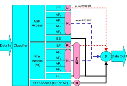
APPENDIX B Example Queuing for a DSL Router... 73
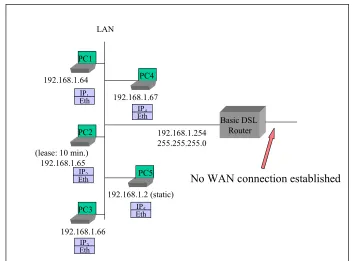
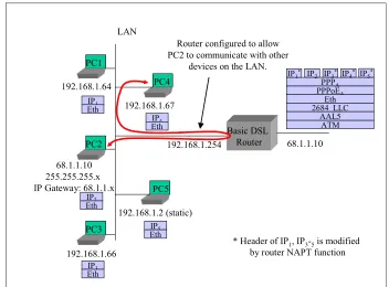
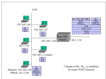
APPENDIX C Routed Architecture – Examples of Potential Configurations... 75
APPENDIX D Bridged Architecture – Examples of Potential Configurations ... 87
APPENDIX E Sealing Current References... 90
Summary
1
Purpose
TR-124 presents a superset of requirements for broadband Residential Gateway devices that are
capable of supporting a full suite of voice, data, broadcast video, video on demand and two-way
video applications in broadband networks.
2
Scope
A Residential Gateway implementing the general requirements of TR-124 will incorporate at
least one embedded WAN interface, routing, bridging, a basic or enhanced firewall, one or
multiple LAN interfaces and home networking functionality that can be deployed as a consumer
self-installable device.
This document specifies a baseline of Residential Gateway device and application functions
needed to support service delivery in routed and bridged broadband network architectures.
Devices can be specified that will operate on any of the different types of Broadband Forum
defined network architectures. This allows service providers to configure a Residential Gateway
device supporting specified TR-124 modular requirements locally via TR-064 and Web
Graphical User Interface or remotely via TR-069.
TR-124 provides optional requirements modules for various physical broadband interfaces (e.g.,
xDSL, Ethernet, GPON) and home networking (LAN) interfaces which may be implemented on
Residential Gateways to meet local service provider needs. Furthermore, to accommodate
common region-specific service provider requirements that do not apply globally, additional
Regional Annexes are included in the TR-124 requirements that may be included in
region-specific product profiles (e.g., North American Power and Environmental requirements).
It is intended that these general requirements modules and WAN/LAN interface modules can be
used as references to define a specific product implementation that may be needed in future
Broadband Forum Technical Reports. This checklist style product profile approach (shown in
the Product Profile Template section in APPENDIX F is intended to provide an easy mechanism
to define a specific product that is needed by region or by service providers. An example of such
a product profile is TR-068 Issue 3 Base Requirements for an ADSL Modem with Routing
which refers to TR-124 feature modules and regional annexes.
These requirements are both backward and forward-looking. They attempt to address the needs
of current DSL services and architectures as well as starting to address future needs. Some
requirements have been included in support of TR-059, TR-064, TR-069, TR-101 and TR-122.
Any CPE that claims to be compliant with these technical requirements must meet the
requirements that reference those documents. It is understood that CPE that does not claim to be
compliant with these referenced requirements may or may not meet any or all of these
2.1
Definitions
2.2
Abbreviations
The following abbreviations apply for purposes of this document:
AAL ATM
Adaptation
Layer
ac alternating
current
ADSL
Asynchronous Digital Subscriber Line
ALG Application
Layer
Gateway
ANSI
American National Standards Institute
ASCII
American Standard Code for Information Interchange
ATA Analog
Terminal
Adapter
ATM Asynchronous
Transfer
Mode
CAT3 Category
3
CAT5 Category
5
CHAP
Challenge Handshake Authentication Protocol
CPE Customer
Premises
Equipment
CRC
Cyclic Redundancy Check
CSA Canadian
Standards
Association
DBRu
Dynamic Bandwidth Report upstream
DHCP
Dynamic Host Configuration Protocol
DMZ Demilitarized
Zone
DNS
Domain Name Server
DoS
Denial of Service
DSCP
Differentiated Services Code Point
DSL Digital
Subscriber
Line
DUID DHCP
Unique
Identifier
EARP
Ethernet Address Resolution Protocol
EIA Electronic
Industries
Alliance
FCC Federal
Communications
Commission
GEM G-PON
Encapsulation
Method
GMT Greenwich
Mean
Time
GSM
Global System for Mobile Communications
GTC
G-PON Transmission Convergence
GUI Graphical
User
Interface
HTML
Hypertext Markup Language
HTTP Hypertext
Transfer
Protocol
HTTPS
Secure Hypertext Transfer Protocol
Hz Hertz
IAID
Identification Association Identifier
IEEE®
The Institute of Electrical and Electronics Engineers
IETF
The Internet Engineering Task Force
IP Internet
Protocol
IPCP
Internet Protocol Control Protocol
ISO
International Organization for Standardization
ITU
International Telecommunication Union
Kbps kilobits
per
second
LAN Local
Area
Network
MAC Medium
Access
Control
MRU
Maximum Receive Unit
ms milli-second
MTBF
Mean Time Between Failure
MTU
Maximum Transit Unit
NRZ
Non Return to Zero
NTP Network
Time
Protocol
ONT
Optical Network Terminal
PAP
PPP Authentication Protocol
PC Personal
Computer
POTS
Plain Old Telephone Service
PPP
Point to Point Protocol
PVC
Permanent Virtual Circuit
SIP Session
Initiation Protocol
SN Serial
Number
SNTP
Simple Network Time Protocol
SSL Secure
Sockets
Layer
TCP Transmission
Control
Protocol
TIA Telecommunications
Industry
Association
TLS Transport
Layer
Security
TR Technical
Report
UDP
User Datagram Protocol
UL Underwriters
Laboratories
ULC
Underwriters Laboratories Canada
USB
Universal Serial Bus
Vac Volts
ac
VCI
Virtual Circuit Identifier
Vdc Volts
dc
VDSL
Very high-speed Digital Subscriber Line
VID VLAN
Identifier
VLAN Virtual
LAN
VoIP Voice
over
IP
WAN Wide
Area
Network
WEP Wireless
Encryption
Protocol
Wi-Fi® Wi-Fi Alliance wireless standards organization
WPA
Wi-Fi Protected Access
WT Working
Text
2.3
Conventions
In this document, several words are used to signify the relative importance of the specified
requirements.
MUST
This word, or the adjective “REQUIRED”, means that the definition is an
absolute requirement of the specification.
MUST NOT
This phrase means that the definition is an absolute prohibition of the
specification.
SHOULD
This word, or the adjective “RECOMMENDED”, means that there may exist
valid reasons in particular circumstances to ignore this item, but the full
implications must be understood and carefully weighted before choosing a
different course.
MAY
This word, or the adjective “OPTIONAL”, means that this item is one which
vendors may readily implement. Other modem features not identified in this
document may also be implemented in the modem and are equivalent to the
MAY
value.
By Default
These words indicate that this is a default setting or operation of the unit which
MUST
be configurable if provided.
Other Residential Gateway type features not identified in this document may also be
implemented in the device. An implementation that includes features not identified in this
document MUST be prepared to inter-operate with implementations that do not include these
features.
References to CPE or LAN devices indicate other equipment such as hosts including PC and
workstations.
3
References
The following Broadband Forum Technical Reports and other references contain provisions,
which, through reference in this text, constitute provisions of this Technical Report. At the time
of publication, the editions indicated were valid. All technical reports and other references are
subject to revision; users of this Technical Report are therefore encouraged to investigate the
possibility of applying the most recent addition of the Technical Report and other references
listed below. A list off the currently valid Broadband Forum Technical Reports is published at
www.broadband-forum.org
.
NOTE – The reference to a document within this Technical Report does not give it, as a
stand-alone document, the status of a Technical Report.
NOTE – A number of IETF drafts are referenced in this document. Due to the fact that home
networking standards and technology are still being rapidly developed, this was considered
necessary. If subsequent drafts or RFCs are published, they will obsolete the draft referenced in
this document.
[1]
ANSI/TIA-968-A-2002 (October 1, 2002), Telecommunications –
Telephone
Terminal Equipment – Technical Requirements for Connection of Terminal
Equipment to the Telephone Network
.
[2]
Broadband Forum TR-059 (September 2003),
DSL Evolution – Architecture
Requirements for the Support of QoS-Enabled IP Services.
[3]
Broadband Forum TR-062 (November 2003),
Auto-Config for the Connection
Between the DSL Broadband Network Termination (B-NT) and the Network using
ATM (TR-037 update).
[4]
Broadband Forum TR-064 (May 2004),
LAN-Side CPE Configuration Specification
.
[5]
Broadband Forum TR-067 (May 2004),
ADSL Interop Test Plan (Formerly TR-048).
[6]
Broadband Forum TR-068 Issue 3 (December 2006),
Base requirement for an ADSL
Modem with Routing.
[7]
Broadband Forum TR-069 (May 2004),
CPE WAN Management Protocol.
[8]
Broadband Forum TR-098 (September 2005),
Internet Gateway Device Version 1.1
Data Model for TR-069
.
[9]
Broadband Forum TR-101 (April 2006),
Migration to Ethernet Based DSL
Aggregation.
[10]
Broadband Forum TR-111 (December 2005),
Applying TR-069 to Remote
Management of Home Networking Devices
.
[11]
Broadband Forum TR-122 (May 2006),
Base Requirements for Consumer-Oriented
Analog Terminal Adapter Functionality
[12]
Broadband Forum TR-133 (September 2005),
DSLHome TR-064 Extensions for
Service Differentiation.
[15]
IEEE EN61000-4-4:2004 (February 2005),
Electromagnetic compatibility (EMC).
Testing and measurement techniques.
[16]
IEEE EN61000-4-5:1995 (September 1995),
Electromagnetic compatibility (EMC).
Testing and measurement techniques. Surge immunity test.
[17]
IEEE Std 802.1DTM-2004 (June 2004),
IEEE standard for local and metropolitan
area networks--Media access control (MAC) Bridges
.
[18]
IEEE Std 802.1QTM (May 7 2003),
IEEE Standards for Local and metropolitan area
networks—Virtual Bridged Local Area Networks
.
[19]
IEEE Std 802.3u (June 2005),
Local and Metropolitan Area Networks-Supplement -
Media Access Control (MAC) Parameters, Physical Layer, Medium Attachment Units
and Repeater for 100Mb/s Operation, Type 100BASE-T (Clauses 21-30).
[20]
IEEE Std 802.11a (September 1999),
Wireless Medium Access Control (MAC) and
physical layer (PHY) specifications: High Speed Physical Layer in the 5 GHz band.
[21]
IEEE Std 802.11b (September 1999),
Wireless LAN Medium Access Control (MAC)
and Physical Layer (PHY) specifications: Higher Speed Physical Layer (PHY)
Extension in the 2.4 GHz band.
[22]
IEEE Std 802.11e (September 2005),
Wireless LAN Medium Access Control (MAC)
and Physical Layer (PHY) Specifications - Amendment: Medium Access Method
(MAC) Quality of Service Enhancements.
[23]
IEEE Std 802.11g (June 2003),
Wireless LAN Medium Access Control (MAC) and
Physical Layer (PHY) Specifications: Further Higher Data Rate Extension in the 2.4
GHz Band.
[24]
IEEE Std 802.11h (September 2003),
Wireless LAN Medium Access Control (MAC)
and Physical Layer (PHY) Specifications - Spectrum and Transmit Power
Management Extensions in the 5 GHz Band in Europe.
[25]
IEEE Std 802.11i (June 2004),
Wireless LAN Medium Access Control (MAC) and
Physical Layer (PHY) specifications: Amendment 6: Medium Access Control (MAC)
Security Enhancements.
[26]
IETF draft-ietf-tcpm-tcpsecure-05 (June 2006),
Improving TCP's Robustness to Blind
In-Window Attacks
.
[27]
IETF RFC 768 (August 28 1980),
User Datagram Protocol
.
[28]
IETF RFC 791 (September 1981),
Internet Protocol
.
[29]
IETF RFC 792 (September 1981),
Internet Control Message Protocol
.
[30]
IETF RFC 793 (September 1981),
Transmission Control Protocol
.
[31]
IETF RFC 826 (November 1982),
An Ethernet Address Resolution Protocol
.
[32]
IETF RFC 894 (April 1984),
A Standard for the Transmission of IP Datagrams over
Ethernet Networks
.
[34]
IETF RFC 1034 (November 1987),
Domain Names - Concepts and Facilities.
[35]
IETF RFC 1035 (November 1987),
Domain Names - Implementation and
Specification.
[36]
IETF RFC 1042 (February 1988),
A Standard for the Transmission of IP Datagrams
over IEEE 802 Networks
.
[37]
IETF RFC 1191 (November 1990),
Path MTU Discovery.
[38]
IETF RFC 1305 (March 1992),
Network Time Protocol (Version 3) Specification,
Implementation and Analysis.
[39]
IETF RFC 1332 (May 1992),
The PPP Internet Protocol Control Protocol (IPCP).
[40]
IETF RFC 1334 (October 1992),
PPP Authentication Protocols (PAP).
[41]
IETF RFC 1570 (January 1994),
PPP LCP Extensions.
[42]
IETF RFC 1661 (July 1994),
The Point-to-Point Protocol (PPP).
[43]
IETF RFC 1867 (November 1995),
Form-based File Upload in HTML.
[44]
IETF RFC 1877 (December 1995),
PPP Internet Protocol Control Protocol
Extensions for Name Server Addresses.
[45]
IETF RFC 1928 (March 1996),
SOCKS Protocol Version 5.
[46]
IETF RFC 1990 (August 1996),
The PPP Multilink Protocol (MP).
[47]
IETF RFC 1994 (August 1996),
PPP Challenge Handshake Authentication Protocol
(CHAP).
[48]
IETF RFC 1948 (May 1996),
Defending Against Sequence Number Attacks
.
[49]
IETF RFC 2091 (January 1997),
Triggered Extensions to RIP to Support Demand
Circuits.
[50]
IETF RFC 2131 (March 1997),
Dynamic Host Configuration Protocol
.
[51]
IETF RFC 2132 (March 1997),
DHCP Options and BOOTP Vendor Extensions
.
[52]
IETF RFC 2153 (May 1997),
PPP Vendor Extensions.
[53]
IETF RFC 2181 (July 1997),
Clarifications to the DNS Specification.
[54]
IETF RFC 2246 (January 1999),
The TLS Protocol Version 1.0
.
[55]
IETF RFC 2364 (July 1998),
PPP over AAL5.
[56]
IETF RFC 2388 (August 1998),
Returning Values from Forms: multipart/form-data.
[57]
IETF RFC 2453 (November 1998),
RIP Version 2.
[58]
IETF RFC 2474 (December 1998),
Definition of the Differentiated Services Field (DS
Field) in the IPv4 and IPv6 Headers.
[59]
IETF RFC 2475 (December 1998),
An Architecture for Differentiated Services.
[61]
IETF RFC 2597 (June 1999),
Assured Forwarding PHB Group.
[62]
IETF RFC 2616 (June 1999),
Hypertext Transfer Protocol -- HTTP/1.1
.
[63]
IETF RFC 2663 (August 1999),
IP Network Address Translator (NAT) Terminology
and Considerations.
[64]
IETF RFC 2684 (September 1999),
Multiprotocol Encapsulation over ATM
Adaptation Layer 5.
[65]
IETF RFC 2818 (May 2000),
HTTP Over TLS
.
[66]
IETF RFC 2939 (September 200),
Procedures and IANA Guidelines for Definition of
New DHCP Options and Message Types
.
[67]
IETF RFC 3022 (January 2001),
Traditional IP Network Address Translator
(Traditional NAT).
[68]
IETF RFC 3027 (January 2001),
Protocol Complications with the IP Network
Address Translator.
[69]
IETF RFC 3246 (March 2002),
An Expedited Forwarding PHB (Per-Hop Behavior).
[70]
IETF RFC 3260 (April 2002),
New Terminology and Clarifications for Diffserv.
[71]
IETF RFC 3261 (June 2002),
SIP: Session Initiation Protocol
.
[72]
IETF RFC 3280 (April 2002),
Internet X.509 Public Key Infrastructure Certificate
and Certificate Revocation List (CRL) Profile.
[73]
IETF RFC 3315 (July 2003),
Dynamic Host Configuration Protocol for IPv6
(DHCPv6).
[74]
IETF RFC 3376 (October 2002),
Internet Group Management Protocol, Version 3.
[75]
IETF RFC 3947 (January 2005),
Negotiation of NAT Traversal in the IKE.
[76]
IETF RFC 3948 (January 2005),
UDP Encapsulation of IPsec ESP packets.
[77]
IETF RFC 4330 (January 2006),
Simple Network Time Protocol (SNTP) Version 4 for
IPv4, IPv6 and OSI
.
[78]
IETF RFC 4361 (February 2006),
Node-specific Client Identifiers for Dynamic Host
Configuration Protocol Version Four (DHCPv4).
[79]
IETF RFC 4541 (May 2006),
Considerations for Internet Group Management
Protocol (IGMP) and Multicast Listener Discovery (MLD) Snooping Switches.
[80]
IETF RFC 4605 (August 2006),
Internet Group Management Protocol (IGMP)
/Multicast Listener Discovery (MLD)-Based Multicast Forwarding ("IGMP/MLD
Proxying")
[81]
IETF RFC 4638 (August 2006),
Accommodating a Maximum Transit Unit/Maximum
Receive Unit (MTU/MRU) Greater Than 1492 in the Point-to-Point Protocol over
Ethernet (PPPoE).
[83]
ISO 8601:2004 (December 2, 2004
), Data elements and interchange formats —
Information interchange — Representation of dates and times
.
[84]
ITU G.984.1
Gigabit-capable Passive Optical Networks (GPON).
[85]
ITU G.984.2
Gigabit-capable Passive Optical Networks (GPON): Physical Media
Dependent (PMD) layer specification.
[86]
ITU G.984.2 Amd1, February, 2006,
Gigabit-capable Passive Optical Networks
(G-PON): Physical Media Dependent (PMD) layer specification Amendment 1: New
Appendix III - Industry best practice for 2.488 Gbit/s downstream, 1.244 Gbit/s
upstream G-PON
[87]
ITU G.984.3
Gigabit-capable Passive Optical Networks (GPON): Transmission
convergence layer specification.
[88]
ITU G.984.4
Gigabit-capable Passive Optical Networks (GPON): ONT Management
and Control Interface specification (OMCI).
[89]
ITU G.992.3 (January 2005),
Asymmetric digital subscriber line transceivers 2
(ADSL2).
[90]
ITU G.993.2 (February 2006),
Very high speed digital subscriber line transceivers 2
(VDSL2).
[91]
ITU G.997.1 (June 2006),
Physical layer management for digital subscriber line
(DSL) transceivers.
[92]
ITU G.998.1 (January 2005),
ATM-based multi-pair bonding.
[93]
ITU G.998.2 (January 2005),
Ethernet-based multi-pair bonding.
[94]
ITU G.9954 (February 2005),
Phoneline networking transceivers - Enhanced
physical, media access, and link layer specifications.
[95]
T1.421-2001,
In-Line Filter for Use with Voiceband Terminal Equipment Operating
on the Same Wire Pair with High Frequency (up to 12 MHz) Devices.
[96]
T1.427.01-2004,
ATM-based Multi-pair Bonding.
[97]
T1.427.02-2005,
Ethernet-based Multi-Pair Bonding.
[98]
UL 60950 Edition 3 (May 15, 2002),
Safety of Information Technology Equipment
.
The following information is given for the convenience of users of this TR and does not
constitute an endorsement by the Broadband Forum of these products.
FireWire® and Safari® are registered trademarks of Apple Computer, Inc.
GSM® is a registered trademark of France Telecom
HomePlug® is a registered trademark of HomePlug Powerline Alliance, Inc.
HomePNA® is a registered trademark of HomePNA, Inc.
Internet Explorer® and Microsoft® are registered trademarks of Microsoft Corporation.
Java® and JavaScript® are registered trademarks of Sun Microsystems, Inc.
Mozilla® is a registered trademark of the Mozilla Foundation.
Netscape® is a registered trademark of Netscape Communications Corporation.
PANTONE® is a registered trademark of Pantone, Inc.
Wi-Fi® is a registered trademark of the Wi-Fi Alliance
WPA, WPA2, Protected Setup, WMM and WMM-SA are trademarks of the Wi-Fi
Alliance
4
Residential Gateway Requirements
Section Item Requirements
GEN
TOCGeneral Device Requirements
DESIGN
TOCDesign
GEN.DESIGN. 1 The device MUST be compact and have a physical profile suitable for desktop.
GEN.DESIGN. 2 The device SHOULD be able to be wall mounted and stand on its side. GEN.DESIGN. 3 The device MAY have the ability to be mounted horizontally or vertically. GEN.DESIGN. 4 If wall mounted, the device SHOULD be oriented so that the cabling is
routed toward the ground in order to reduce strain on the cabling. GEN.DESIGN. 5 A detachable wall-mounting bracket MAY be added to the device. GEN.DESIGN. 6 The power connector at the device MUST be securely connected to avoid
accidental disconnect. This means that the connector MUST be either secured via a clip to the box or be held in place with significant force so that it does not readily pull out by minor pulling on the power cord. GEN.DESIGN. 7 If the power supply is external to the device, it SHOULD be labeled with
the device vendor’s name and the model number of the device. GEN.DESIGN. 8 If the power supply is external to the device it SHOULD be either small
enough, or appropriately positioned on the power cord, so as not to block other power outlets.
GEN.DESIGN. 9 If the power cable includes an analog to digital conversion brick, that brick MAY have a light on it.
GEN.DESIGN. 10 The device MUST NOT be USB powered.
GEN.DESIGN. 11 The device MUST NOT use the local phone loop for power.
GEN.DESIGN. 12 The model and serial number MUST be visible via external markings on the device.
GEN.DESIGN. 13 The model and serial number MUST be visible via external markings on the product packaging.
Section Item Requirements
device it SHOULD NOT be physically accessible to end users (e.g. it should not be placed on the outside of the device).
GEN.DESIGN. 15 The device MUST have a single function reset button in order to reset the device to the default factory settings.
OPS
TOCDevice Operation
GEN.OPS. 1 All device firmware and associated system files MUST be pre-installed. GEN.OPS. 2 The device MUST operate 24 hours a day, 7 days a week without the
need to reboot.
GEN.OPS. 3 The MTBF (Mean Time Between Failure) of the device and operating system SHOULD be equal to or exceed 1 year (e.g., it should not need a reboot more than one time per year).
GEN.OPS. 4 The life expectancy of the device SHOULD be at least seven years. GEN.OPS. 5 The Device SHOULD be tolerant of power fluctuations and brown-outs,
continuing to operate normally and maintaining its configuration after these events.
GEN.OPS. 6 The device SHOULD be able to detect faults and reset appropriately upon detection.
GEN.OPS. 7 The device SHOULD include sufficient non-volatile memory to accommodate future control and data plane protocol upgrades over a minimum of four years. The potential upgrades may include: initiating and terminating signaling protocols at IP and ATM layers; logic for packet classification, policing, forwarding, traffic shaping and QoS support at both IP and ATM layers.
GEN.OPS. 8 This device MUST preserve local configuration information during power-off and power interruption.
GEN.OPS. 9 The device MUST complete power up in 60 seconds or less (timing starts when the power is connected and stops when the On/Off power indicator light is "Solid Green").
GEN.OPS. 10 The device SHOULD be self-installable by an end user in under 20 minutes assuming the default configuration and mode of operation for the device. This is the time from when the box is opened to when the user is using the service including any driver installation (assuming no network complications and excluding micro-filter installation and customer ordering/registration).
GEN.OPS. 11 Other than networking drivers (e.g., USB, wireless, etc…), other software or drivers MUST NOT be required on computers and other devices for proper and full use of the device.
GEN.OPS. 12 The device, drivers and any packaged software SHOULD support Macintosh OS 8.6 and above.
GEN.OPS. 13 The device, drivers and any packaged software SHOULD support all Microsoft PC based operating systems which have not yet reached "End of Life" status (see
http://www.microsoft.com/windows/lifecycleconsumer.mspx for more details).
Section Item Requirements
GEN.OPS. 15 The device MUST preserve its configuration across firmware updates. GEN.OPS. 16 All software revisions SHOULD be backward compatible with all previous
versions. There SHOULD be no loss of existing functionality.
GEN.OPS. 17 Software revisions MUST NOT require service provider network changes to maintain proper operation of previous features.
GEN.OPS. 18 The device firmware MUST be identified by a revision number. This revision number MUST be formatted using an X.Y.Z incremental numbering format where X indicates the major release number, Y indicates the minor release number, and Z represents the revision number (e.g. 2.4.1).
GEN.OPS. 19 The vendor SHOULD have a web site where firmware updates and documentation is available.
GEN.OPS. 20 The firmware at the vendor's web site SHOULD include all error correcting updates for the device.
GEN.OPS. 21 The device MUST NOT allow "back door" entry to the unit (e.g., there must be no hidden telnet or web access using secret passwords). GEN.OPS. 22 All firmware updates MUST be verified using security mechanisms. A
checksum mechanism is a minimum requirement for achieving this. GEN.OPS. 23 All firmware updates SHOULD be verified using a cryptographic
"fingerprint" of at least 256 bits.
GEN.OPS. 24 In the event of a failure occurring during an update, the device MUST be able to back off to the prior version of the firmware installed on the device. That is, the prior version of the device's firmware MUST continue to be useable in the event that a firmware update fails to complete. This is not a requirement for a dual image, although that is one manner in which this requirement might be achieved.
NET
TOCNetworking Protocols
GEN.NET. 1 The device MUST support Ethernet (IEEE 802.3). GEN.NET. 2 The device MUST support IP Version 4.
GEN.NET. 3 The device SHOULD be software configurable or upgradeable to support IP Version 6 in the future. This means that the processing power, memory and networking components must be designed appropriately and be sufficiently robust to provide this support.
GEN.NET. 4 The device MUST support the TCP, IP, UDP, routing and associated protocols identified here:
- IETF RFC 0768 User Datagram Protocol - IETF RFC 0791 Internet Protocol
- IETF RFC 0792 Internet Control Message Protocol - IETF RFC 0793 Transmission Control Protocol
- IETF RFC 0826 Ethernet Address Resolution Protocol (ARP) - IETF RFC 0894 Standards for the Transmission of IP Datagrams over Ethernet Networks
- IETF RFC 0922 Broadcasting Internet Datagrams in the Presence of Subnets
- IETF RFC 0950 Internet Standard Subnetting Procedure
Section Item Requirements
- IETF RFC 1042 Standard for the Transmission of IP Datagrams over IEEE 802 Networks
- IETF RFC 1112 Host Extensions for IP Multicasting
- IETF RFC 1122 Requirements for Internet Hosts - Communication Layers
- IETF RFC 1123 Requirements for Internet Hosts - Application and Support
- IETF RFC 1256 ICMP Router Discovery Messages (Router Specification only)
- IETF RFC 1519 Classless Inter- Domain Routing (CIDR) - IETF RFC 1812 Requirements for IP Version 4 Routers - IETF RFC 1918 Address Allocation for Private Internets - IETF RFC 3600 Internet Official Protocol Standards - IANA Directory of General Assigned Numbers (http://www.iana.org/numbers.html)
GEN.NET. 5 The device MUST support IP over Ethernet.
GEN.NET. 6 The device MUST support, at a minimum, a 256 MAC address table for LAN devices.
WAN
TOCWide Area Networking (WAN)
ATM
TOCATM
WAN.ATM. 1 The device MUST support standard ATM (AAL5) payload format. Note this satisfies TR-101 R-338.
WAN.ATM. 2 The device MUST perform AAL Segmentation and Reassembly (SAR), Convergence Sublayer (CS) functions and CRC check.
WAN.ATM. 3 The device MUST support encapsulation of bridged Ethernet over AAL5 (without FCS) as described in IETF RFC 2684 (formerly IETF RFC 1483). WAN.ATM. 4 The device MUST be able to use both LLC-SNAP and VC-MUX (null)
encapsulation over AAL5 with all supported protocols. The default MUST be LLC-SNAP.
WAN.ATM. 5 The device MAY support encapsulation of IP over AAL5, per IETF RFC 2684.
WAN.ATM. 6 If the device supports IP over AAL5, it MAY support Classical IP according to IETF RFC 2225.
WAN.ATM. 7 The device MUST support ATM CoS. UBR, CBR and VBR-rt MUST be supported (as defined in The ATM Forum Traffic Management Specification Version 4.1).
WAN.ATM. 8 VBR-nrt and UBR with per VC queuing SHOULD be supported. WAN.ATM. 9 The default ATM CoS for the primary VC MUST be UBR.
WAN.ATM. 10 The device SHOULD support auto configuration as defined in Broadband Forum TR-062 and ILMI 4.0 and its extensions.
WAN.ATM. 11 The device MUST always respond to ATM testing, pings and loopbacks according to ITU-T I.610 (F4, F5).
WAN.ATM. 12 The device SHOULD support initiating an ATM Loopback, and receiving the reply. This satisfies TR-101 R-337.
Section Item Requirements
TR-101 R-339.
WAN.ATM. 14 The device MUST support 0/35 as the default VPI/VCI for the first PVC or use an operator-specific configuration.
WAN.ATM. 15 The device MUST be able to perform an auto search for the VPI/VCI settings for the first PVC based on a defineable search list VPI/VCI sequence order.
If the modem reaches a state of session establishment (e.g., IP when the modem is responsible for session termination) after performing the auto search, the default VPI/VCI settings MUST be set to the newly discovered values. The new default pair MUST be stored on the modem across power off situations. If an ATM connection cannot be established after power is restored, the search process starts over again.
WAN.ATM. 16 The device MUST support the following default VPI/VCI auto-search list programmed as a factory default setting in the following sequence, or use an operator-specific sequence configuration:
0/35, 0/38, 8/35, 0/43, 0/51, 0/59, 8/43, 8/51.
This default list MUST be overwriteable via the methods discussed in WAN.ATM.19
WAN.ATM. 17 The device MUST be configurable so that the auto-search mechanism can be disabled.
WAN.ATM. 18 The device MUST allow the auto-search list to be redefined using Broadband Forum TR-064 and TR-069.
WAN.ATM. 19 The default VPI/VCI values for all PVCs MUST be configurable. The default value MUST be utilized prior to performing an auto-search but should exclude the default value in the auto-search.
WAN.ATM. 20 The device MUST support VPI values from 0 to 255 WAN.ATM. 21 The device MUST support VCI values from 32 to 65535
ATM.MULTI
TOCATM Multi-PVC
WAN.ATM.MULTI. 1 The device MUST support eight PVCs. This is in addition to support for any implemented ATM UNI control path PVCs (e.g. ILMI
auto-configuration PVC, etc.).
WAN.ATM.MULTI. 2 The device MUST allow the protocol stack (e.g., IP over Ethernet, PPPoE, PPPoA, etc…) for each provisioned PVC to be defined separately. If necessary, each PVC can use a different stack and set of protocols. WAN.ATM.MULTI. 3 There is no default defined VPI/VCI for additional PVCs past the primary
PVC defined in WAN.ATM above. The device MUST support auto-search function (see WAN.ATM.17 through 20) on all PVCs and will use the same auto-search sequence identified (skipping over any already in use). WAN.ATM.MULTI. 4 All supported PVCs MUST NOT require the same VPI value. WAN.ATM.MULTI. 5 All supported PVCs MUST be able to be active and sending/receiving
traffic simultaneously. See requirements LAN.FWD.8, 10, 11 and 15 for more details on interface selection for routing.
Section Item Requirements
associated DSL protocol in use on a per VC and VP basis.
For example, ATM granularity of 32 kbps MUST be supported for ADSL on a per VC and VP basis.
WAN.ATM.MULTI. 7 The device MUST use the same Ethernet MAC address for all interfaces over the same AAL5/ATM/DSL connection.
WAN.ATM.MULTI. 8 The device MUST support multiple levels of CoS simultaneously across separate VCCs (e.g., UBR for PVC 0/35 and CBR for PVC 0/43 where both PVCs are active simultaneously).
CONNECT
TOCConnection Establishment
WAN.CONNECT. 1 The device MUST support an "always on" mode for connections. In this mode the device MUST NOT time out connection sessions (ATM, IP and PPP) and MUST automatically re-establish any sessions after
disconnection, lease expiration or loss and restoration of power.
WAN.CONNECT. 2 The device MUST support a “connect on demand” option for connections. In this mode the connection to the broadband network is initiated when outbound traffic is encountered from the local LAN and terminated after a timeout period in which no traffic occurs.
WAN.CONNECT. 3 The device MUST support a “manual connect” option for connections. In this mode the connection to the broadband network is initiated manually through the GUI or via TR-064/TR-069 request and, by default, terminates only when done so explicitly by the user, due to a power loss or when the connection is lost.
WAN.CONNECT. 4 The interval after which a connection timeout occurs MUST be able to be configured.
WAN.CONNECT. 5 A manual way of disconnecting without waiting for a connection timeout MUST be provided.
WAN.CONNECT. 6 A default timeout of 20 minutes SHOULD be used for connection timeouts or use an operator-specific configuration.
WAN.CONNECT. 7 The device MUST follow all standards required to perform an orderly tear down of the associated connections involved at the associated network levels (e.g., issue a DHCPRELEASE message when using DHCP, issue LCP Terminate-Request/Terminate-Ack and PADT packet when using PPPoE, etc.) and then restart the connections.
WAN.CONNECT. 8 The device MUST detect the loss of communications with a network identified DNS server as indicated by a failed query, and upon failed query, log the event.
ETHOAM
TOCEthernet OAM
WAN.ETHOAM. 1 The device MUST support a Maintenance Association End Point (MEP) on a per VLAN basis. Note: The multi-PVC case is for further study. This satisfies TR-101 R-251.
WAN.ETHOAM. 2 The device MUST support a default ME level value of 5 for the Customer Level. This satisfies TR-101 R-252.
Section Item Requirements
WAN.ETHOAM. 4 The device MUST support a Loopback Reply (LBR) function towards its peer MEP(s) in response to both unicast and multicast LBMs. This satisfies TR-101 R-254.
WAN.ETHOAM. 5 The device MUST support a Linktrace Reply (LTR) function towards its peer MEP(s). This satisfies TR-101 R-255.
WAN.ETHOAM. 6 For business customers and/or premium customers requiring proactive monitoring, the device SHOULD support generating Continuity Check Messages (CCMs). This satisfies TR-101 R-256.
WAN.ETHOAM. 7 The device MUST support turning off sending of CCMs, while keeping the associated MEP active. This satisfies TR-101 R-257.
WAN.ETHOAM. 8 The device MUST support receiving AIS messages. This satisfies TR-101 R-258.
WAN.ETHOAM. 9 The device SHOULD trigger the appropriate alarms for Loss of Continuity. This satisfies TR-101 R-259.
WAN.ETHOAM. 10 The device MUST support a default ME level value of 1 for the Access Link level. This satisfies TR-101 R-261.
WAN.ETHOAM. 11 The device SHOULD support a Loopback Message (LBM) function that can generate a Multicast LBM towards its peer MEP(s). This requirement allows the device to dynamically learn the MAC address of the AN MEP, and test the connectivity to that MEP. Notice that the ability for the device to generate a multicast LBM at the Customer level and at the Access Link level are sufficient to test connectivity to the near edge of the carrier’s network and to the BNG, which are the only two points that are visible to the device. A Linktrace initiation capability would provide no added value. Upon receiving a LBM, the device must respond to it by initiating a LBR. In other words, it must support the LBM sink function and the LBR source function. This satisfies TR-101 R-262.
WAN.ETHOAM. 12 The device MUST support a Loopback Reply (LBR) function towards its peer MEP(s), in response to both unicast and multicast LBMs. This satisfies TR-101 R-263.
BRIDGE
TOCBridging
WAN.BRIDGE. 1 The device MUST be able to bridge IP over Ethernet.
WAN.BRIDGE. 2 The device MUST be a learning bridge as defined in IEEE 802.1D for all logical and physical Ethernet interfaces, supporting a minimum of 272 MAC addresses.
WAN.BRIDGE. 3 If bridge mode is enabled on the device by default for LAN connected devices, the device MUST be able to support additional connections for TR-069 remote management addressability (using direct DHCP or Static IP, PPP, etc.), and connections for any locally terminated service which require IP addressability (e.g. gateway integrated Voice ATA ports, etc.).
Note that this special bridge mode that includes a device remote management session connection requires an additional WAN connection from the network. This requirement is considered conditional as a result due to the network side dependency, but the device must support this type of configuration.
Section Item Requirements
WAN.DHCPC. 1 The device MUST be able to obtain IP network information dynamically on its WAN interface. This information includes IP address, primary and secondary DNS addresses and default gateway address.
Dynamically obtaining IP network information is accomplished using DHCP and / or IPCP.
WAN.DHCPC. 2 If the device is not configured to use a static IP address and the modem fails to detect a PPPoE or DHCP server, then the WAN IP address assignment value SHOULD be set to an undefined value, in order to prevent it from retaining its prior IP address.
WAN.DHCPC. 3 If a device is functioning as a DHCP client, it MUST identify itself in option 61 (client-identifier) in every DHCP message in accordance with IETF RFC 4361 (February 2006), Node-specific Client Identifiers for Dynamic Host Configuration Protocol Version Four (DHCPv4).
WAN.DHCPC. 4 For the DUID portion of option 61 in DHCPv4 as described in IETF RFC 4361, the device MUST follow the DUID-EN format specified in section 9.3 of RFC 3315. The device MUST use Broadband Forum enterprise-number value 3561 in DUID-EN enterprise-enterprise-number field.
For the identifier field of the DUID-EN, the CPE MUST use an ASCII string containing the same content and formatted according to the same rules as defined for HTTP username in Section 3.4.4 of TR-069 Amendment 1
.
WAN.DHCPC. 5 The device IAID value in DHCPv4 and DHCPv6 MUST be a 32 bit number encoded in network byte order. In cases where the device is functioning with a single DHCP client identity, it MUST use value 1 for IAID for all DHCP interactions. IAID is defined in IETF RFC 3315.
In cases where the device is functioning with multiple DHCP client identities, the values of IAID have to start at 1 for the first identity and be incremented for each subsequent identity. The device's mapping of IAID to its physical aspects or logical configuration SHOULD be as non-volatile as possible. For example, the device MAY use IAID value 1 for the first physical interface and value 2 for the second. Alternatively, the device MAY use IAID value 1 for the virtual circuit corresponding to the first connection object in the data model and value 2 for the second connection object in the data model.
WAN.DHCPC. 6 The DUID-EN field value MAY be printed on the product label on the bottom of the device.
WAN.DHCPC. 7 A device functioning as a DHCP client MUST identify its manufacturer OUI, product class, model name and serial number using vendor-specific options as defined in IETF RFC 3925. Specifically, it MUST use option 125.
Section Item Requirements
serves as an opaque, but predictable identifier. It is predictable because it is the same identifier as used by device for interactions with other services. The same identifier is used for HTTP authentication and in SSL client certificates.
Each sub-option value to be provided in option 125 MUST be treated as string encoded into binary using UTF-8. The data MUST be encapsulated in option 125 under enterprise code 3561 in decimal (0x0DE9 in
hexadecimal), corresponding to the IANA “ADSL Forum” entry in the Private Enterprise Numbers registry. A specific sub-option is defined for each value and the value must match a corresponding TR-069 / TR-106 parameter as defined in the following table:
Sub-option Value Description Corresponding TR-069 / TR-106 parameter 1 Manufacturer OUI .DeviceInfo.ManufacturerOUI
2 Product Class .DeviceInfo.ProductClass 3 Model Name .DeviceInfo.ModelName 4 Serial Number .DeviceInfo.SerialNumber
If the value of a parameter is empty for the device, then the sub-option MUST be omitted.
PPP
TOCPPP Client
WAN.PPP. 1 The device MUST support PPP and the associated protocols as defined in IETF RFCs 1332, 1334, 1661, 1877, 1994.
WAN.PPP. 2 The device MUST support IETF RFCs 1570 and 2153 traffic and operate without fault. This is not stating that specific extensions MUST be supported directly. It is identifying that upon receipt of non-standard or unrecognized PPP extensions from the broadband network (e.g., vendor or proprietary), the device MUST operate without fault.
WAN.PPP. 3 The device MUST support PPPoE over the encapsulated Ethernet as defined in IETF RFC 2516.
WAN.PPP. 4 The device MUST support IETF RFC 4638 in order to accommodate MTU/MRU values greater than 1492 bytes in PPPoE.
WAN.PPP. 5 If the device supports ATM, the device SHOULD support PPP over AAL5 (PPPoA) as defined in IETF RFC 2364.
WAN.PPP. 6 The device MUST be able to save all logins and passwords for PPP sessions originated by the device. Passwords MUST NOT be available outside of the internal operation of the device (e.g., can not be queried nor displayed).
WAN.PPP. 7 The device MUST not immediately terminate PPPoE sessions and upper layer protocol connections when the physical connection is lost. It should defer the tear down process for two minutes. If the physical connection is restored during that time, the device MUST first attempt to use its previous PPPoE session settings. If these are rejected, then the original PPPoE session can be terminated and a new PPPoE session attempted. WAN.PPP. 8 The device SHOULD incorporate a random timing delay prior to starting
Section Item Requirements
WAN.PPP. 9 The device SHOULD not attempt immediate additional PPP session connections upon receipt of an authentication failure. A back off mechanism SHOULD be implemented to limit repeated attempts to reconnect in this situation. 3 connection attempts SHOULD be made followed by a delay and then repeated by the next sequence of connection attempts. The delay SHOULD be 5 minutes at first, and then repeated every 30 minutes as required. This requirement only applies to automated connection attempts.
WAN.PPP. 10 If the device is using PPPoE client function actively, the device MUST be able to forward PPPoE sessions initiated from LAN devices as additional PPPoE sessions to the WAN interface (this is sometimes known as PPPoE pass-through). Specifically these LAN initiated PPPoE sessions MUST NOT be tunneled inside the device's primary PPPoE client session. WAN.PPP. 11 If the network implements the TR-059 type architecture, and when
fragmentation is required, the device MUST fragment all PPP sessions that it originates on an access VC using MLPPP interleaving as defined in IETF RFC 1990.
WAN.PPP. 12 If PPP is used, the device MAY obtain an IP subnet mask on its WAN interface using IPCP extensions. If this is done, then IP subnet masks will be communicated with IPCP using the PPP IPCP option with option code 144, the length of the option being 6 and the mask being expressed as a 32-bit mask (e.g. 0xFFFFFF80), not as a number indicating the
consecutive number of 1s in the mask (from 0 to 32).
The learned network information MAY, but need not, be used to populate the LAN side embedded DHCP server for the modem.
The learned network information is treated as a subnet and not as a collection of individual addresses. That is, the first and last address in the subnet should not be used.
The IP address negotiated SHOULD, but need not, be the one assigned to the modem.
WAN.PPP. 13 The device MUST make the access concentrator name used with PPPoE connections available via the Web GUI, TR-064 or TR-069 request for diagnostic purposes.
dot1x
TOC802.1x Client
WAN.dot1x. 1 The device MUST support IEEE 802.1X™ acting as a supplicant. WAN.dot1x. 2 The device MUST be able to respond to an appropriate IEEE 802.1X
request and provide certificate information using Extensible Authentication Protocol-Transport Layer Security (EAP/TLS).
WAN.dot1x. 3 The device SHOULD support EAP-MD5 username and password type authentication.
WAN.dot1x. 4 The device MUST support receiving IEEE 802.1X EAPOL frames with an individual MAC address (i.e., unicast) as well as frames with a group MAC address (i.e., multicast).
Section Item Requirements
WAN.dot1x. 6 The device MUST be able to store certificate information used to authenticate the authenticator.
WAN.dot1x. 7 The device MUST be able to update the information used to validate the authenticator by either a firmware upgrade or via updated certificates. WAN.dot1x. 8 The device SHOULD be able to update the information used to validate
the authenticator by updated certificates without a firmware upgrade. WAN.dot1x. 9 The device MUST be able to store information allowing it to authenticate a
minimum of eight authenticators.
WAN.dot1x. 10 When used with IP over Ethernet and DHCP, if the device already has a connection when receiving an IEEE 802.1X request, the device SHOULD subsequently perform a DHCP lease renewal upon successful 802.1X authentication.
WAN.dot1x. 11 Each device MUST have a unique factory-installed private/public key pairs and embedded ITU-T X.509 Version 3 / IETF RFC 3280 certificate that has been signed by the supplier's device certificate authority.
WAN.dot1x. 12 The device certificate MUST have a validity period greater than the operational lifetime of the device.
DoS
TOCDenial of Service Prevention
WAN.DoS. 1 The device MUST provide Denial of Service (DOS) protection for itself and all LAN CPE including protection from Ping of Death, SYN Flood LAND and variant attacks. The extent of this protection will be limited when the device is configured as a bridge in which only PPPoE traffic is bridged. This protection MUST be available when the device terminates IP or bridges IP.
WAN.DoS. 2 The device MUST reject packets from the WAN with MAC addresses of devices on the local LAN or invalid IP addresses (e.g., broadcast addresses, private IP addresses or IP Addresses matching those assigned to the LAN Segment).
WAN.DoS. 3 The device MUST reject any unidentified Ethernet packets (i.e. any packet that is not associated with IP or PPPoE protocols).
QoS
TOCQuality of Service
WAN.QoS. 1 The device MUST support classification of WAN directed LAN traffic and placement into appropriate queues based on any one or more of the following pieces of information:
(1) destination IP address(es) with subnet mask, (2) originating IP address(es) with subnet mask, (3) source MAC address,
(4) destination MAC address, (5) protocol (TCP, UDP, ICMP, …) (6) source port,
(7) destination port,
(8) IEEE 802.1D Ethernet priority,
(9) FQDN (Fully Qualified Domain Name) of WAN session, (10) Diffserv codepoint (IETF RFC 3260),
(11) Ethertype (IEEE 802.3, 1998 Length/Type Field), and (12) traffic handled by an ALG, and
Section Item Requirements
WAN.QoS. 2 The device MUST support classification of WAN directed LAN traffic and placement into appropriate queues based on any one or more of the following pieces of information:
(1) packet length.
WAN.QoS. 3 The device MUST support the differentiated services field (DS Field) in IP headers as defined in IETF RFC 2474.
WAN.QoS. 4 The device MUST by default recognize and provide appropriate treatment to packets marked with recommended Diffserv Codepoints, whose values and behavior are defined in IETF RFC 2474, 2475, 2597, 3246, and 3260. Specifically, the values shown in the DSCP column of the table below MUST be supported, except the Cs0-7, which are optional.
DSCP marking DSCP marking Class Description (name) (decimal value) EF Realtime ef 46 AF4 – in-contract Premium class4 (in) af41 34 AF4 – out-of-contract Premium class4 (out) af42, af43 36, 38 AF3 – in-contract Premium class3 (in) af31 26 AF3 – out-of-contract Premium class3 (out) af32, af33 28, 30 AF2 – in-contract Premium class2 (in) af21 18 AF2 – out-of-contract Premium class2 (out) af22, af23 20, 22 AF1 – in-contract Premium class1 (in) af11 10 AF1 – out-of-contract Premium class1 (out) af12, af13 12, 14 DE/BE Default / Best Effort be 0 Cs0 (optional) Class Selector 0 cs0 0 Cs1 (optional) Class Selector 1 cs1 8 Cs2 (optional) Class Selector 2 cs2 16 Cs3 (optional) Class Selector 3 cs3 24 Cs4 (optional) Class Selector 4 cs4 32 Cs5 (optional) Class Selector 5 cs5 40 Cs6 (optional) Class Selector 6 cs6 48 Cs7 (optional) Class Selector 7 cs7 56
WAN.QoS. 5 The device MUST be able to mark or remark the Diffserv codepoint or IEEE 802.1D Ethernet priority of traffic identified based on any of the classifiers supported by the device.
WAN.QoS. 6 The device SHOULD support sending the following frame types: untagged frames, priority-tagged frames, and VLAN-tagged frames in the upstream direction. This satisfies TR-101 R-01.
WAN.QoS. 7 The device SHOULD support setting the priority tag and VLAN ID values. This satisfies TR-101 R-02.
WAN.QoS. 8 The device SHOULD support receiving untagged and VLAN-tagged Ethernet frames in the downstream direction, and SHOULD be able to strip the VLAN tagging from the ones received tagged. This satisfies TR-101 R-03.
WAN.QoS. 9 The device MUST support one Best Effort (BE) queue, one Expedited Forwarding (EF) queue and a minimum of four Assured Forwarding (AF) queues.
WAN.QoS. 10 The device MUST duplicate the set of queues for each access session. This can be done logically or physically.
WAN.QoS. 11 The device SHOULD support the appropriate mechanism to effectively implement Diffserv per hop scheduling behaviors. A strict priority scheduler is preferred for EF.
Section Item Requirements
WAN.QoS. 13 The device SHOULD support per-class shaping of upstream traffic. WAN.QoS. 14 The device MUST support the capability to fragment traffic on sessions
that it originates, in order to constrain the impact of large packets on traffic delay.
WAN.QoS. 15 The packet size threshold before fragmenting AF and BE packets MUST be configurable.
LAN
TOCLocal Area Networking (LAN)
GEN
TOCGeneral LAN Protocols
LAN.GEN. 1 The device MAY support SOCKS as defined in IETF RFC 1928 for non-ALG access to the public address.
LAN.GEN. 2 Both NetBios and Zero Config naming mechanisms MAY be used to populate the DNS tables.
LAN.GEN. 3 The device MAY act as a NETBIOS master browser for that name service. LAN.GEN. 4 The device MUST support multiple subnets being used on the local LAN.
ADDRESS
TOCPrivate Addressing
LAN.ADDRESS. 1 The device MUST be able to be configured to specify alternate public and private subnets (without restriction) for local device addressing.
LAN.ADDRESS. 2 The device MUST be able to be configured to specify the start and stop addresses within a subnet used for local addressing.
LAN.ADDRESS. 3 The device MUST NOT use auto IP for address assignment of its LAN-side address.
LAN.ADDRESS. 4 The device MUST allow its assigned address and netmask to be specified through the Web GUI and via TR-064/TR-069 interfaces.
LAN.ADDRESS. 5 If the device is in bridged configuration and LAN side configuration is enabled, the device MUST ARP on the LAN side for the following addresses, in order, and assign itself the first one that is not taken: 192.168.1.254, 192.168.1.63, and then starting from 192.168.1.253 and descending.
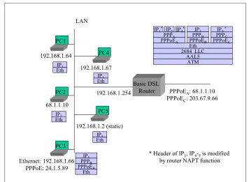
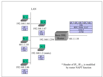
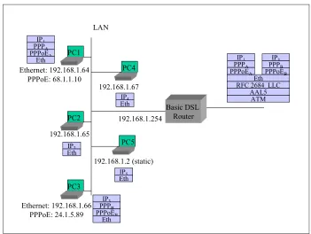
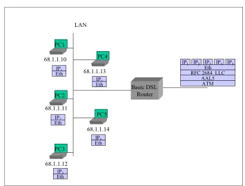
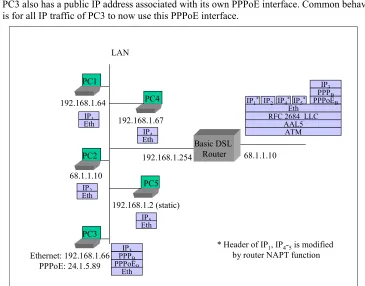
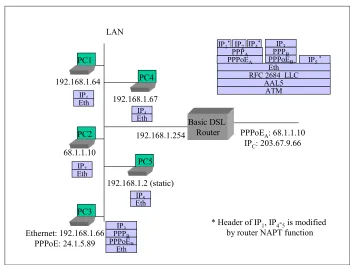
LAN.ADDRESS. 6 The device MUST be able to assign its own WAN IP address (e.g., public address) to a particular LAN device, concurrent with private IP addressing being used for other LAN CPE.
In this situation, one device on the LAN is given the same public IP address (through DHCP or manual configuration of the LAN CPE IP stack). Other LAN devices utilize private IP addresses. The device can then be configured as identified in LAN.PFWD.2 so that the LAN device "sharing" the WAN IP address receives all unidentified or unsolicited port traffic to any specific LAN device. If the device is not configured in this manner, then only inbound traffic resulting from outbound traffic from the LAN CPE would be directed to that LAN CPE.
Section Item Requirements
LAN.ADDRESS. 7 When operating in multiple WAN public IP address mode, the device MUST support the up to 16 public IP addresses being used by LAN devices (statically or dynamically issued) and whose traffic must be routed to and from the public IP address associated with the LAN device. Additionally, a Transparent Basic NAT mapping feature MAY be supported, allowing the 16 public address to be mapped to a device's private address. A user configurable option in the Web GUI MUST be provided to enable or disable the firewall on a per public IP basis. This feature must operate concurrently with other LAN usage (e.g., NAPT on the gateway's primary IP address).
LAN.ADDRESS. 8 When using a WAN IP address assigned to a LAN device, the user MUST be able to configure if this LAN device can directly communicate with other devices on the local LAN without the need to traverse the broadband connection.
This will only be done to the extent which the device can control the isolation (e.g., routing and internal switch fabric). It does not extend to isolation external to the device (e.g., external switch or router) which are outside of the control of the device.
DHCPS
TOCDHCP Server
LAN.DHCPS. 1 The device MUST provide application layer support for host name mapping, booting, and management including DHCP and the Domain Name System (DNS) protocol. This includes support for the standards below:
- IETF RFC 1034 Domain Names - Concepts and Facilities
- IETF RFC 1035 Domain Names - Implementation and Specification - IETF RFC 2131 Dynamic Host Configuration Protocol
- IETF RFC 2132 DHCP Options and BOOTP Vendor Extensions - IETF RFC 2181 Clarifications to the DNS Specification
- IETF RFC 2939 Procedure for Defining New DHCP Options and Message Types
LAN.DHCPS. 2 The device MUST be a DHCP server to local LAN devices, supporting all LAN devices.
LAN.DHCPS. 3 The embedded DHCP server function of the device MUST be able to operate while in bridged mode. The default state should be on in bridged and routed mode.
LAN.DHCPS. 4 The device MUST support a minimum of 253 LAN devices.
LAN.DHCPS. 5 The device MUST support turning off the embedded DHCP server via a configuration change locally via the Web GUI and remotely via TR-064/TR-069 interfaces.
LAN.DHCPS. 6 The device MAY incorporate auto-detection of other DHCP servers on the local LAN and, if configured to do so, disable the internal DHCP server functionality of the device in this situation.
In this situation, the device would try to obtain a configuration for its LAN port through DHCP. If a DHCP response was received, the device would then use the information in the DHCP response (e.g., IP Address, subnet and DNS information) and disable its internal DHCP server. If
Section Item Requirements
precedence over requirement LAN.DHCPS.15.
LAN.DHCPS. 7 The embedded DHCP server functionality of the device MUST verify that an address is not in use prior to making it available in a lease (e.g., via Ping or ARP table validation) even when lease information shows that it is not in use.
LAN.DHCPS. 8 If the device is in a routed configuration (i.e. full NAPT router), the device MUST use the default start address of 192.168.1.64 and the default stop address of 192.168.1.253 for assignment to DHCP leases for local device addressing, or use an operator-specific configuration.
LAN.DHCPS. 9 If the device is in a routed configuration (i.e. full NAPT router), the device MUST use a default netmask of 255.255.255.0 for assignment to DHCP leases for local device addressing, or use an operator-specific
configuration.
LAN.DHCPS. 10 If the device is in a bridged configuration for LAN device traffic (i.e. NAT/NAPT is not enabled), the device MUST support the enabling and configuration of the local device DHCP server (address range and subnet mask) remotely via TR-069 interface. This address range may be either public or private addresses (assuming that the service provider is providing the NAT/NAPT function in the network).
Note that this assumes that a separate management IP interface has been established to the device expressly for the purpose of TR-069 remote management.
LAN.DHCPS. 11 The default lease time for DHCP information provided to LAN CPE which do not share the WAN side IP address MUST be configurable. The default value MUST be 24 hours, or use an operator-specific configuration. LAN.DHCPS. 12 The default lease time for DHCP information provided to LAN CPE which
share the WAN side IP address MUST be configurable. The default value MUST be 10 minutes, or use an operator-specific configuration.
LAN.DHCPS. 13 When the domain name that the embedded DHCP server passes to LAN CPE has not been set, the value "domain_not_set.invalid" SHOULD be used.
LAN.DHCPS. 14 If the device is in a routed configuration (i.e. full NAPT router) and the device's embedded DHCP server is enabled, the device itself MUST default to the address 192.168.1.254 (with a netmask of 255.255.255.0), or use an operator-specific configuration.
LAN.DHCPS. 15 When the device's embedded DHCP server is disabled, the device MUST ARP for the following addresses, in order, and assign itself the first one that is not taken: 192.168.1.254, 192.168.1.63, and then starting from 192.168.1.253 and descending.
LAN.DHCPS. 16 The device MAY allow the embedded DHCP server to be configured so that specific MAC addresses can be identified as being served or not served.
LAN.DHCPS. 17 The device MAY allow the embedded DHCP server to be configured with a default setting (provide IP addresses or do not provide IP addresses) for devices with unspecified MAC addresses.
Section Item Requirements
device by MAC address. The user interface to establish this association may use an alternate mechanism to identify this assignment (e.g., by selecting the device using its current IP address or device name) and the MAC address may be transparent to the user. These addresses may include the ability to assign an address within the default subnet or an address from additional public/private subnets that may be provisioned.
For example, the device might have a default WAN side IP address which is used for NAPT to a subset of devices and an additional set of WAN side IP addresses which are bridged. The embedded DHCP server might be used to assign this second set of IP addresses to specific LAN CPE. LAN.DHCPS. 19 The device MUST support a single PC mode of operation. In this mode of
operation only a single LAN device is supported. Note that this is not the default mode of operation.
In this configured mode, all network traffic, except for configured
management traffic destined for the modem itself (e.g., temporary remote access to the Web GUI) MUST be passed between the access network and the designated LAN device as if the device was not present.
One possible implementation is for the embedded DHCP server to issue one and only one private address in this situation, with the start and stop address for the embedded DHCP server being the same.
The LAN device can be assigned either a private IP address (i.e., using 1:1 NAT) or the public IP address of the modem (i.e., using IP Pass-through as identified in requirement LAN.ADDRESS.6). The type of IP address to be used (private or public) is configured through the Web GUI and TR-064/TR-069 interfaces. The default is a public IP address.
If a WAN connection is not available when the device is configured to use a public IP address, the LAN device is provided with a private IP address from the device via DHCP. Once a WAN connection is established, the public IP address provided by the broadband network is passed to the LAN device during the next DHCP lease renewal.
The Broadband Residential Gateway acts as the default gateway to the LAN devices when private IP addressing is in use. When public IP addressing is in use, the gateway identified to the LAN device should be that identified in requirement LAN.ADDRESS.6 above.
No other restrictions (e.g., restricted routing for other devices) need to be implemented to meet this requirement (e.g., no routing restrictions on traffic from secondary devices on the LAN).
LAN.DHCPS. 20 If the device is configured in a routed configuration (i.e. full NAPT router), the device MUST operate by default in the multiple PC mode of operation, or use an operator-specific configuration.
DNS
TOCNaming Services
Section Item Requirements
LAN.DNS. 2 The device SHOULD allow the user to specify that the network learned or user specified DNS addresses be passed back to the LAN devices in DHCP responses instead of the device's address itself as the DNS name server(s).
LAN.DNS. 3 When the device learns DNS name server addresses from multiple WAN connections, the device MUST query a server on each connection simultaneously and provide the requesting LAN client with the first returned positive result from these DNS servers. A negative response will not be transmitted to a LAN device until all WAN DNS servers have either timed out or returned a negative response to a common query.
Service providers may choose not to provide DNS name server addresses on certain connections in a multiple connection configuration.
LAN.DNS. 4 The device MUST add the DNS entry "dsldevice" for its own address. LAN.DNS. 5 The device MAY support additional DNS entries, as there could be
additional types of CPE.
LAN.DNS. 6 The device MUST maintain local DNS entries for a minimum of 253 local LAN devices. This information can be obtained through auto discovery (e.g., from DHCP requests, such as Client Identifier, and other protocol information). When unknown, the entry MUST be of the form
"unknownxxxxxxxxxxxx" where "x" represents the MAC address of the associated LAN device.
LAN.DNS. 7 The device SHOULD provide a manual mechanism for overriding the learned names of all LAN CPE except that for the Broadband Residential Gateway itself.
NAT
TOCNAT/NATP
LAN.NAT. 1 The device MUST support Network Address Port Translation (NAPT; also known as Port Address Translation) as defined in IETF RFCs 2663, 3022 a