A Review of Study about Design and Analysis of
Gravity Dam
Jayendra Parmar1, Prof. Sumit Pahwa2 1
M.Tech. Student, 2Associate Professor, Department of Civil Engineering, AIT, Ujjain (M.P.), India
Abstract: This paper presents a comprehensive review of published literature on gravity dams. The construction of dam at suitable site is needed on those rivers which carry huge amount of rain water. It is needed to review the work carried out by different researchers in context of the especial need arisen at Lucknow in river Gomti, where the construction of dam is to be carried out in flowing water without diverting it. A gravity dam is a solid structure, made of concrete or masonry, built throughout a river to create a reservoir on its upstream. The segment of the gravity dam is approximately triangular in shape, with its apex at its pinnacle and most width at backside. The phase is so proportioned that it resists the numerous forces acting on it by using its very own weight.
Keywords: Concrete Gravity Dam, Dam Failure, Design, Stability and Stress, concrete.
I. INTRODUCTION
[image:1.612.212.416.533.706.2]A dam is a barrier that is constructed across a river or stream so the water can be held back or impounded to supply water for drinking or irrigation, to control flooding, and to generate power. The main kinds of dams are earth fill, rock fill, concrete gravity, concrete arch, and arch gravity. The last three types are all made of concrete, reinforced concrete, or masonry. (The term masonry can mean concrete, bricks, or blocks of excavated rock). Fill dams include all dams made of earth materials (soil and rock) that are compacted together. One type of fill dam called a tailings dam is constructed of fine waste that results from processing rock during mining; at mine sites, this soil-like waste is compacted to form an embankment that holds water for the mining and milling processes or to retain the tailing themselves in water. Gravity dams are solid concrete structures that maintain their stability against design loads from the geometric shape and the mass and strength of the concrete. Generally, they are constructed on a straight axis, but may be slightly curved or angled to accommodate the specific site conditions. Gravity dams typically consist of a non-overflow section and an overflow section or spill- way. Earthquakes have affected several large concrete dams in the past. Although no catastrophic failure has yet been reported unless a dam crossed a fault, historical events have shown that severe seismic damage could be imparted to concrete dams. Gravity dams are structures that rely on their own weight for resistance against sliding and overturning to maintain stability. Loads due to seismic excitation are one of the most important actions that must be considered in concrete dam design, even in regions of low seismic activity. Traditional procedures for concrete dam design consider forces due to seismic excitation as equivalent static forces which are obtained by the addition of part of the reservoir to the structural mass.
II. GRAVITY DAM LOAD COMBINATION Factors to be considered as contributing to the loading combinations for a gravity dam are:
A. Reservoir and tail water loads.
B. Temperature.
C. Internal hydrostatic pressure.
D. Dead weight.
E. Ice.
F. Silt.
G. Earthquake.
Such factors as dead weight and static water loads can be calculated accurately. Others such as earthquake, temperature, ice, silt, and internal hydrostatic pressure must be predicted on the basis of assumptions of varying reliability.
Dead weight is the gravity affecting the dam itself, since we are dealing with compact, heavy structures this is a major factor. This is a static load as well as the others, except for earthquake.
Hydrostatic pressure from reservoir is the pressure created by the upstream water.
Hydrostatic pressure from tail water affects the dam the same way as the hydrostatic pressure caused by reservoir water does, with the only difference that it is the pressure from the water downstream of the dam.
Internal hydrostatic pressure is what we also call uplift pressure. This is the pressure from the water in the foundation and in the dam body that will push the dam body upward, causing an enhanced risk of sliding. This is especially problematic for gravity dams since they cover a greater area than other types of concrete dams.
Sand and silt is the load applied as an earth pressure from eroded material at the upstream face of the dam. It is usually reasonably small compared to the hydrostatic reservoir pressure.
Ice load affects the upstream face of the dam, as the surface of the water freezes. If the ice gets thick enough it will cause a significant load. Load is concentrated to a small surface where the dam body is thinnest.
Temperature is a concern both during the construction phase and the entire lifespan of the dam. The hardening of the concrete causes severe temperature variations that will lead to strains. Depending on where in the world the dam is located the temperature changes may continue, during the entire lifespan of the dam, to be an important issue.
Earthquake is a dynamic load. This load is, unlike the other seven, very hard to predict but is very important to consider in earthquake affected regions.
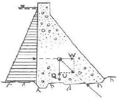
[image:2.612.222.400.527.709.2]Earthquake or seismic loads are the major dynamic loads being considered in the analysis and design of dams especially in earthquake prone areas. The seismic coefficient method is used in determining the resultant location and sliding stability of dams. Seismic analysis of dams is performed for the most unfavorable direction, despite the fact that earthquake acceleration might take place in any direction.
Figure 2 and 3 shows the seismic coefficient α for dynamic loads on a gravity dam. There are different ways of computing
earthquake loads on dams. The deterministic approach may be employed where the ground acceleration in terms of g (acceleration
due to gravity) is specified for the region where the dam will be constructed.
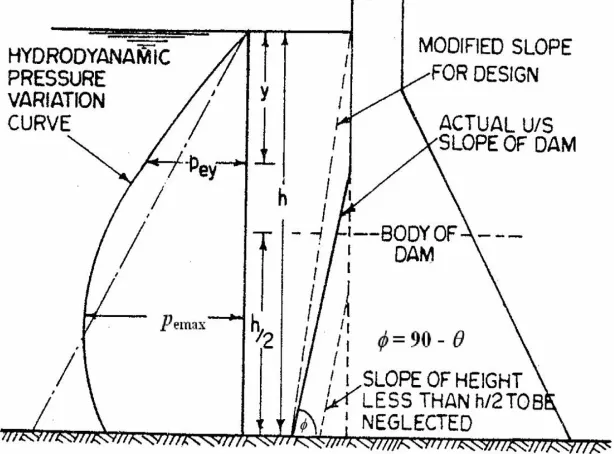
Figure 3: Dam structure
The hydrodynamic pressure exerted along dam-reservoir interface is given by:
where
where Pex, M, ax, W, α, g are the horizontal earthquake force on the dam, mass horizontal earthquake acceleration, weight,
acceleration due to gravity and seismic coefficient respectively. Also, Pew, h, te are the additional total water load down to depth y,
total height of reservoir, and period of vibration respectively [3].
III. LITERATURE SURVEY
Gravity dam is designed for various forces especially for the overturning moment and for the sliding forces. Proper design is also required to safeguard against piping which is a severe problem in the design of Gravity dam.
[image:3.612.153.460.121.348.2]dimensions and material properties a 2D finite element model of the dam is simulated using ANSYS APDL R.18.2. The stress results found through both approaches are tabulated and are compared for the accuracy of manual calculations. In reservoir full condition compressive stress develops at the toe and tensile stress at the heel, it also has been observed that stress distribution pattern is slightly different for manual and FEM results.
Shyamal Pise et. al. (2018) studied about stresses analysis of koyna dam of 103.00m high above ground level with varying thickness in accordance with IS 6512. This dam has been analysed for different types of load using ANSYS software by assuming fixity at the base. The analysis of dam structure has been carried out using 8 noded SHELL 181 elements with uniform SHELL thicknesses. By finite element Analysis 16, a three-dimensional finite element model of Koyna gravity dam is proposed using ANSYS 16. Dams with full reservoir and empty reservoir condition are analysed. In this study, normal stress shear stress and deflection along X and Y direction is observed. The rectangular opening of 4×4 m is more effective than circular opening of same size. The stresses and deformation are less in case of rectangular opening and to reduce the deflection rectangular opening should be at bottom near hill of gravity dam.
Mohammad Ejaz Shahir et. al. (2017) the main aim of present work is to perform a complete 3D seismic analysis of concrete gravity dam using PGA (peak ground acceleration) of Afghanistan Cities. For present analysis four different cases were selected with and without opening for drainage gallery. The complete seismic analysis of concrete gravity dam is presented in this study including static, modal, harmonic and response spectrum analysis using ANSYS software. In the static analysis, the maximum stresses are found at heel for case 1 and case 2, but as we introduce opening in case 3 and case 4, the maximum stresses are around the opening. The maximum values of stresses and deformation are observed in case 3. In harmonic response, the maximum deformation is observed around downstream and upstream section near change in cross-section area.
J H Durieux et. al. (2016) A case study of a completed gravity dam is analysed, comparing several analysis techniques. The service and extreme load cases are investigated. Different material properties for the concrete and rock, including weathered material along the base of the wall, are considered. The application and merits of the DP NL FEM are presented. The calculation of the critical factor of safety against sliding is done with a more realistic determination of the conditions along the base of the wall. One advantage of the NL DP FEM is that the DP parameters can readily be obtained from standard material laboratory tests.
Pooja A. Patil et. al. (2016) the objective of study is comprising of the Finite Element Method which considers the size of opening, elastic property of material, and stress distribution because of geometric discontinuity in cross section of dam. The first step of simulation is aimed to validate the models developed by comparing them to previous work. In this study, normal stress shear stress and deflection along X and Y direction is observed. The rectangular opening of 4×4 m is more effective than circular opening of same size. The stresses and deformation are less in case of rectangular opening and to reduce the deflection rectangular opening should be at bottom near hill of gravity dam.
Nishtha Saraswat et. al. (2016) They studied about Dams are gaining more attention in recent years due to the rise of the environmental awareness and ‘renewable energy’ and ‘sustainability’ concepts. Earth embankment dams are preferred over gravity dams for the ease of construction and economical advantage. Rock-fill dam is a type of earth dam where a compacted central clay core is supported from the rock shells by a series of transition zones built of properly graded material. A 2D fem analysis is done by modelling the dam as a linear, elastic, non-homogenous material. Among the variables, the non-homogeneity of the core and shell material and coefficient of friction is considered in the analysis. On evaluation it is found that core settlement increases where core-shell influence has been considered.
Pooja A. Patil et al.(2016) They studied about Drainage gallery is very critical in case of gravity dam. Numerical three-dimensional FEA flow analysis is a very efficient method for the stress analysis of the subsurface drainage systems of concrete gravity dams. The gravity method of the analysis does not consider the size of opening and the elastic property of dam material. Thus, the objective of study is comprising of the Finite Element Method which considers the size of opening, elastic property of material, and stress distribution because of geometric discontinuity in cross section of dam.
L. K. Gudukeya et. al. (2015) In this study a three-dimensional finite element model implemented in ABAQUS is used for simulating the temperature behaviour in operational phase of typical arch dam. For dynamic analysis, a coupled system of dam and reservoir is considered. The static loads are compared and combined with earthquake load. Results show significant thermally induced tensile stresses in the crest region and at the downstream face of the dam, which is the most vulnerable zone for seismic induced damage.
included. Analysis of the gravity dam has been carried out and the influence of soil properties has been studied at the region of transverse sections, which exhibited the response in terms of stress and deformation with significant difference.
Dinesh Ajayakumar et. al. (2015) They studied about over five thousand years, as evident in the cradles of civilization, dams have played an important role in regulating water flow to cater to the needs of irrigation. They endow important quantities of water that are absolutely crucial for human consumption and industries, in addition to irrigation. This has become a necessity to ensure the safety of people as the damages caused by the failure of dam can be catastrophic. Here an attempt is made to develop a Finite Element Model of an arch dam, which can be used to analyze stresses and deformations that would occur in the dam.
Cong Zeng et. al. (2015) They studied about Theoretical profile stress and displacement of a certain non-overflow gravity dam in a key water-control project was studied in this study. Plane finite element method and dam-rock coupling effect were both considered. It is concluded that the tensile stress concentration was appeared at the heel and toe of dam, especially the dam heel with significant compression. Therefore, the former position is of great importance in the design. However, the stress is still less than the strength of dam concrete and foundation rock, which is means the seismic design of the non-overflow gravity is reasonable. Moreover, it is indicated that the damrock coupling effect will significantly affect the simulation results.
Bakenaz A. Zeidan et. al. (2015) They studied about Investigation of the behavior of dams against seismic loads is a key factor for dam safety requirements. One of the most important problems in evaluation of seismic behavior of concrete gravity dams is dam-reservoir-foundation interaction. The dam and foundation have been idealized by considering linear, elastic and plane stress conditions. The effect of foundation flexibility has been obtained by considering various dam-foundation rock interaction ratios i.e. modulus of elasticity of foundation to modulus of elasticity of dam. Results show that both foundation mass and flexibility have an outstanding impact on the behavior of dams and is necessary to consider their impact while simulating seismic response of concrete gravity dams.
Zaki Mohsin et. al. (2015) They studied about A 2D (Plain strain) dam ‒ reservoir ‒ foundation interaction is modeled using finite element method by ANSYS to find the optimum design based on the principle of fluid-structure and soil-structure interactions analyses. The components of the optimization process are the objective function OBJ is to minimize the volume of the dam, the state variables stresses, strains, and displacements of dam, and the design variables DVs are the dimensions of the dam. The results show that the piles or secant piles beneath the dam are necessary to improve bearing capacity factor, scaling the optimum section for economy, and to reduce seepage. It is concluded that the finite element method simulated by ANSYS is efficient with the optimization process.
IV. CONCLUSION
By studying a no of researches carried out by the learned researchers we found that they are all concerned to dam design and construction on such a site where there are no water present at work site or the construction site is first vacated by the construction of coffer dam or through sheet piling. The study is further carried out to observe the change in analysis values of moments, vertical and horizontal actions with change in seismic zones. For same loading and geometry consideration, when analysis is done for various seismic zone, it is observed that
values of +ve moment remains constant whereas the value of –ve moment increased with increase in earthquake severity zone wise. This highlights instability against overturning. Again, it is observed that value of vertical forces remained unchanged but seismic forces increases value of horizontal forces which resulted in instability against sliding.
REFERENCES
[1] Manoj Nallanathel, B. Ramesh, Pavan Kumar Raju, "Stability Analysis of Concrete Gravity Dam Using Staad Pro", International Journal of Pure and Applied Mathematics, Volume 119 No. 17 2018, 297-310.
[2] Khalid Dawlatzai, Manju Dominic, "Structural Stability And 2d Finite Element Analysis of Concrete Gravity Dam", International Journal of Engineering Science Invention (IJESI), Volume 7, Issue 1, January 2018.
[3] Shyamal Pise, G. R. Patil, "Numerical Study of Gravity Dam with Gallery Study under Influence of Sloshing Wave Using ANSYS.16", Journal of Advances and Scholarly Researches in Allied Education, Vol. XV, Issue No. 2, April-2018.
[4] Mohammad Ejaz Shahir, Priyanka Dhurvey, "Seismic Response of Concrete Gravity Dam in Afghanistan", International Research Journal of Engineering and Technology (IRJET), Volume 04, Issue 06, June -2017.
[5] H Durieux, B W J van Rensburg, "Development of a practical methodology for the analysis of gravity dams using the non-linear finite element method", Journal of the South African Institution of Civil Engineering, Vol 58 No 2, June 2016, Pages 2–13, Paper 708.
[6] Pooja A. Patil, G.B. Katti, "Finite Element Analysis of Gravity Dam with Drainage Gallery in Ansys Workbench 14.5", International Journal of Modern Trends in Engineering and Research, Volume 3, Issue 4, April 2016.
[8] Pooja A. Patil and G. B. Katti, “Finite Element Analysis of Gravity Dam with Drainage Gallery in Ansys Workbench 14.5”, “International Journal of Modern Trends in Engineering and Research”, 28-30 April, 2016.
[9] L. K. Gudukeya, C. Mbohwa, "Thermal Stress Analysis of a Dam Wall by Finite Element Model", Proceedings of the World Congress on Engineering, 2015. [10] Shiva Khosravi and Mohammad Mehdi Heydari, “Design and Modal Analysis of Gravity Dams by Ansys Parametric Design Language”, “Engineering and
Physical Science”, 12(2), 2015.
[11] S.A. Neshaei, M. K. Abadi and R. Vahedzadegan, “Investigation of crack development in concrete dams due to water level fluctuation during earthquakes”, “River Basin Management”, 271-281, 2015.
[12] Patil Swapnal V., “Effect of Soil Structure Interaction on Gravity Dam”, “International Journal of Science, Engineering and Technology Research”, 1046-1053, 2015.
[13] Dinesh Ajayakumar, Girija K. and Anand Raj, “Static Analysis and Safety Evaluation of an Arch Dam”, “International Journal of Innovative Research in Science, Engineering and Technology”, 8369-8372, 2015.
[14] Cong Zeng, Dongxue Hao, Liqun Hou, Wen Pan and Hexian Su, “Seismic Performance of Non-overflow Gravity Dam Considering Dam-rock Coupling Effect”, “AASRI International Conference on Industrial Electronics and Applications”, 171-174, 2015.
[15] Atheer Zaki Mohsin, Hassan Ali Omran and Abdul-Hassan K. Al-Shukur, “Optimum Design of Low Concrete Gravity Dam on Random Soil Subjected to Earthquake Excitation”, “International Journal of Innovative Research in Science, Engineering and Technology”, 8961-8973, 2015.