Using ontology mapping to automate derivation
of transformations for data integration
D.G.A. Stolp
Thesis for a Master of Science degree in Telematics
University of Twente
Faculty of Electrical Engineering,
Mathematics and Computer Science
February 2009
Graduation Committee:
Dr. ir. M.J. van Sinderen
Dr. ir. M.W.A. Steen
Dr. L. Ferreira Pires
Abstract
The Purchase Order Mediation scenario of the Semantic Web Service challenge describes an interoperability problem, in which two companies want to do busi-ness, and need to integrate their IT systems. Within the A-MUSE project, a solution to this problem is devised that uses ontologies to describe the two IT systems. This solution requires a tool that can create mappings between these two ontologies, and use these mappings to generate the necessary data transformations.
This master thesis describes the research and development process that resulted in the creation of that tool. A state-of-the-art survey was conducted which resulted in an overview of existing ontology matching algorithms and mapping tools. These findings confirmed that there is currently no tool that can readily be used, and provided the necessary knowledge to start the development of a mapping editor.
3
Acknowledgment
4
Preface
This thesis is the resulting product of my Master’s assignment, which I have carried out at the Telematica Instituut. During the process of doing research, developing a software tool and ultimately writing this thesis, a lot of people have provided valuable assistance. I hereby would like to thank everyone for their contribution to this work.
A small number of people deserve a special acknowledgement. My direct super-visors and graduation committee: Maarten Steen at the Telematica Instituut, for providing the opportunity to do the assignment in the first place, and for his continuing efforts to steer my research in the right direction. Marten van Sinderen at the University of Twente, his suggestions and feedback have made this thesis more academically sound and better structured. And Luís Ferreira Pires, whose last-minute suggestions made this thesis all the more readable and correct.
I would like to thank Stanislav Pokraev at the Telematica Instituut for his help. He came up with more ideas and suggestions than five Master students could implement, but they always helped to improve the product. Thankfully, Jaap Reitsma was there to help me pick out the most relevant and doable ideas, and to assist in their implementation.
A big thank you goes out to my parents. Regrettably, my mother passed away just before I started this assignment, but I will always remember her for her interest and unconditional support. My father’s curiosity and advice over the years made it possible for me to come to where I am now: writing a preface for my completed Master’s thesis, with the prospect of a fun and challenging career.
Finally, I would like to thank my girlfriend Marlous very much for her continuing motivation, patience and advice. Our conversations helped me structure my own ideas, and her suggestions often made the text in this thesis more complete and understandable. Her support for me during this assignment has been invaluable. Daan Stolp
Contents
1 Introduction 9
1.1 The Semantic Web Services challenge . . . 10
1.1.1 The Purchase Order Mediation scenario . . . 10
1.1.2 Solutions to the challenge . . . 12
1.2 The solution of the A-MUSE project . . . 12
1.2.1 Transform the IT domain to the business domain . . . 12
1.2.2 Semantic enrichment of business service descriptions . . . 14
1.2.3 Solving the integration problem at the business layer . . . 14
1.2.4 Transform the solution back to the IT domain . . . 14
1.3 Aim of this research . . . 15
1.4 Research approach . . . 15
1.5 Structure of this thesis . . . 16
2 State-of-the-art in ontology mapping 18 2.1 Ontology mapping algorithms . . . 18
2.2 Ontology mapping tools . . . 19
3 Development Iterations 22 4 Iteration 1 Starting the project 26 4.1 Goals . . . 26
4.2 User stories . . . 26
4.3 Design . . . 28
4.4 Solutions and decisions . . . 29
6 CONTENTS
5 Iteration 2
Relate two ontologies 32
5.1 Goals . . . 32
5.2 User stories . . . 32
5.3 Design . . . 33
5.3.1 The OwlCat file format . . . 34
5.3.2 The conversion process . . . 34
5.4 Solutions and decisions . . . 37
5.4.1 Alter the editor or convert the input . . . 37
5.4.2 Avoid infinite loops caused by circular references . . . 38
5.5 Evaluation . . . 41
6 Iteration 3 Create meaningful mappings 42 6.1 Goals . . . 42
6.2 User stories . . . 42
6.3 Design . . . 44
6.3.1 The owl2owl mapping meta-model . . . 44
6.3.2 Editing the mapping information . . . 45
6.4 Solutions and decisions . . . 45
6.4.1 Storing the information . . . 45
6.4.2 TheOwlMappingRelationType class . . . 47
6.5 Evaluation . . . 48
6.5.1 An alternative way to encode the function names . . . 48
7 Iteration 4 Save and export the mappings 49 7.1 Goals . . . 49
7.2 User stories . . . 49
7.3 Design . . . 50
7.3.1 File format . . . 50
7.3.2 The export function . . . 51
7.4 Solutions and decisions . . . 53
7.4.1 Save vs. Export . . . 53
CONTENTS 7
8 Resulting architecture 55
8.1 Architecture of the mapping editor . . . 55
8.1.1 Eclipse . . . 55
8.1.2 The Eclipse Modeling Framework . . . 56
8.1.3 Ecore2Ecore mapping editor . . . 56
8.1.4 OWL2OWL . . . 57
8.1.5 OWL2EMF . . . 57
8.1.6 MDSL . . . 57
8.2 Design of the editor’s modules . . . 57
8.2.1 OWL2OWL and the ecore2ecore module . . . 58
8.2.2 OWL2EMF . . . 59
8.2.3 MDSL . . . 60
9 Case study: Purchase Order Mediation scenario 62 9.1 Goals for the case study . . . 62
9.2 Method . . . 63
9.2.1 The process . . . 63
9.2.2 The owl2owl mapping editor . . . 64
9.2.3 Configuring the mediator . . . 68
9.3 Results . . . 68
9.3.1 Issues regarding the process . . . 69
9.3.2 Issues regarding the editor . . . 69
9.4 Evaluation . . . 71
10 Discussion and reflection 73 10.1 The input and output of the mapping editor . . . 73
10.1.1 Input . . . 74
10.1.2 Output . . . 76
10.2 The tool as part of the entire process . . . 77
10.3 Improvement opportunities . . . 78
10.4 Comparison with existing solutions . . . 79
10.4.1 The editor’s output . . . 80
10.4.2 Degree of automation . . . 80
8 CONTENTS
11 Conclusions and future work 82
11.1 Conclusions . . . 82
11.2 Future work . . . 84
11.2.1 Mapping editor improvements . . . 84
11.2.2 Research and development opportunities . . . 85
References 87 A Installation and operation instructions 90 A.1 Requirements . . . 90
A.2 Installation . . . 90
Chapter 1
Introduction
From the first moment that IT systems were being used in businesses, people were looking for ways to interconnect them. These interconnections allow for even more automation of business processes than individual IT systems can achieve. However, since most vendors of IT systems used their own format for data storage and communication, implementing such interconnections has never been an easy task. Over the course of time, numerous technologies have been developed that aim to make this process as easy as possible. In the last couple of years, research has focused mostly on the use of Web Services to achieve this task.
While Web Services facilitate the exchange of messages between two systems, this is only part of the interconnection problem. The other problem is that both systems may use different concepts, different ways to represent real-world entities. If you want to interconnect the two systems, you need to make sure that both systems understand each other’s concepts, or at least that there is a mediator or ‘interpreter’ that can translate back and forth between the systems. This means that the systems should not only know how to represent messages exchanged with the other party (syntax), but also what the other partymeans
with the messages it exchanges (semantics).
In order to make the semantics clear, Web Services can be ‘enriched’ with se-mantic information. Currently, research is conducted in order to find out how to best apply and make use of this semantic information, such that an automated interconnection of two systems becomes possible.
10 Introduction
systems can be interconnected, could add a percentage point to global GDP (Bugajski, as cited in [8]).
From the above, it should be clear that automated, or partially automated solutions for interconnecting IT systems can play a big role in the current IT industry. One initiative that tries to stimulate research into this topic is the Semantic Web Services Challenge.
1.1 The Semantic Web Services challenge
The topic of this research is based on the work on the Semantic Web Service Challenge (SWS Challenge) [24]. This is an international challenge organized by DERI Stanford1 and has participants from universities, research institutes,
and commercial businesses. Its goal is “to develop a common understanding of various technologies intended to facilitate the automation of mediation, chore-ography and discovery for Web Services using semantic annotations”. In order to achieve that goal, they created several problems that the participants need to solve.
This initiative is indeed set up as a challenge rather than a contest, meaning that workshop participants mutually evaluate and learn from each other’s ap-proaches.
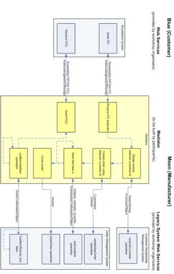
The problem scenario that this thesis focuses on is the Purchase Order Media-tion scenario. In this scenario, two fictitious companies want to do business and link their IT systems. However, both parties use different systems and commu-nication protocols. Because of this they cannot directly communicate to each other. The challenge is therefore to design a mediator that allows the companies to link their IT systems and do business.
1.1.1 The Purchase Order Mediation scenario
In the SWS Challenge, two companies want to do business. These are Blue Com-pany and Moon ComCom-pany, who have the roles of customer and manufacturer, respectively, in the SWS Challenge scenario. Both companies have external interfaces to their IT systems in the form of web services. The WSDL specifi-cations of these services, as well as a natural language description, are given by the SWS Challenge organizers.
Even though both parties use Web Services, this alone is not enough to ensure interoperability. The problem is that both parties use different choreographies and data representations. Blue company adheres to the RosettaNet specifica-tion, while Moon Company uses a proprietary legacy system. So even though it is technically possible for Blue Company to send a message to Moon Com-pany, the latter will not understand the contents of the message. The mediator that is to be built, must enable Moon company to understand and exchange RosettaNet messages with outside parties (Blue Company). An overview of the scenario is given in figure 1.1. More details can be found on the SWS Challenge website [24].
1.1 The Semantic Web Services challenge 11
12 Introduction
1.1.2 Solutions to the challenge
One way of looking at the problem that is proposed by the SWS Challenge is to divide it into two separate but related problems. Blue company uses different terms, names, and entities than Moon company, so there is a data mismatch. However, the order in which operations are called, the way responses are sent, errors are handled, etc. also differ between Blue and Moon company, so there is also abehavior mismatch. All solutions that are proposed need to solve both these sub-problems in order to solve the challenge.
The literature research on this topic [23] contains a more detailed overview of various solutions to the challenge. For clarity, the solution of the A-MUSE project is discussed below.
1.2 The solution of the A-MUSE project
As part of the Freeband A-MUSE project, the Telematica Instituut and the Center for Telematics and Information Technology (CTIT) of the University of Twente are working on a solution to solve the problem proposed by the challenge. The entire approach is described by Quartel et al. in [19] and [18]. The goal is to design and develop a mediator that conforms to Evaluation Success Level 2. This means that only the data used by this mediator (e.g. configuration files) needs to be changed when the problem level changes, not the application code. So if either of the parties decides to change their data or behavior models, only a reconfiguration of the mediator is required, not recompilation.
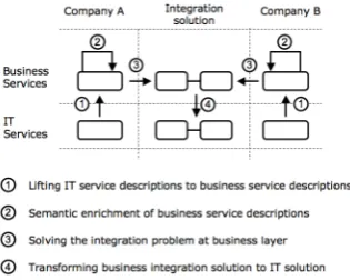
The Telematica Instituut and CTIT try to lift the solution to a higher level, away from the technicalities of the IT systems and more towards the business domain. In that case, the integration problem can be tackled directly by business domain experts. In contrast, nowadays the domain experts usually compile a requirements document that is sent to IT experts. The IT experts then build the integration solution, but this is often paired with miscommunication and misinterpretation between the business domain experts and the IT experts. In order to accomplish this shift from the technical domain to the business domain, four steps are necessary (see figure 1.2). First, the service description of the IT systems needs to be transformed into a format that can be used by the domain experts. By adding semantic information, the technical descriptions get meaning. Then, the integration problem needs to be solved at the business layer. Finally, the solution needs to be transformed back to an IT solution. The following sections describe this process.
1.2.1 Transform the IT domain to the business domain
1.2 The solution of the A-MUSE project 13
Figure 1.2: The necessary transformation in the solution.
behavior model. This process is described in more detail in [18]. The informa-tion model is called anontology, which is represented using the Web Ontology Language (OWL). The behavior model can be represented using languages that support behavior representation, such as ISDL.
The concept ontology and the OWL language play an important part in this research. The following text box gives for a short introduction to ontologies and the Web Ontology Language (OWL).
Ontologies and OWL
The termontology can have a different meaning, depending on the industry or context within which it is used. One definition that is very useful, and widely used, from the viewpoint of the IT industry, is the one by Gruber [10]. He defines an ontology as:
“a set of representational primitives with which to model a domain of knowledge or discourse”
These primitives are usually classes, attributes, and relationships. Using these primitives, it is possible to give meaning and constraints to the entities that describe the domain. These “semantic” properties of ontologies distinguish them from simple data models or database schemas. In addition, languages for specifying ontologies are usually completely independent from lower level data models. And this, according to Gruber, makes them a good tool for integrating different systems.
14 Introduction
1.2.2 Semantic enrichment of business service descriptions
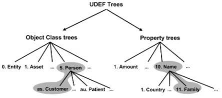
The next step is to add semantic information to the information models. This is information about relations or properties of entities that are present in the real world, but which are not encoded in the web services and WSDL documents of the IT systems. One way to achieve this is by using the Universal Data Element Framework (UDEF). UDEF provides globally standard identifiers with which one can tag elements in ontologies. One can now relate two different ontologies by looking at the associated UDEF tags.
[image:14.595.214.436.305.403.2]This tagging is mostly a manual process. It requires knowledge from domain experts in order to make the correct semantic enrichment. The UDEF is struc-tured as a hierarchical tree, so finding the most appropriate tag for a particular element means going through the tree top-down until the most appropriate tag for the element is found.
Figure 1.3: UDEF tree
1.2.3 Solving the integration problem at the business layer
When the problem is completely lifted from the IT domain to the business domain and the semantic information has been added, the integration problem can be tackled. This means that inconsistencies or mismatches in the data models and behavior models need to be solved. First, the relations between different elements in the two information models need to be defined. Second, these relations need to be formulated using some formal language. When this is done, it becomes possible to transform these mappings back to the IT domain. Not only the information models need to be mapped, but also inconsistencies between the behavior models need to be solved. If, for example, one party expects an acknowledgement to a message, but the other party never sends such an acknowledgement, there is a mismatch. Such mismatches should also be solved by either automatically or manually identifying the mismatches and proposing solutions to solve them.
1.2.4 Transform the solution back to the IT domain
1.3 Aim of this research 15
to transformation specifications. These specifications ‘translate’ messages from one format to another, based on the relations that were specified in the previous step.
The behavior is translated into a BPEL specification. Using BPEL, the se-quence, ordering and types of messages can be manipulated in order to facilitate interoperability between the two parties.
1.3 Aim of this research
This research focuses on the last two steps, namely the specification of the mappings between ontologies and the translation of those mappings to the IT domain by generating the required transformations. Furthermore, this research only deals with the mapping of information. The mapping of behavior to BPEL is dealt with o.a. in [5] and is not part of this research.
The specification of mappings or relations between concepts is always neces-sary in integration solutions. However, the problem with ‘traditional’ mapping approaches is that the domain experts, who need to map the concepts, and the technology experts, who have to implement the mappings on a technical level, have a hard time communicating with each other and staying on the same course. This results in a lot of communication overhead and at worst, even in-complete or incorrect mappings. The solution that is proposed in this thesis is to minimize the required communication between the domain and the technology experts by creating a tool that is able to create the technical transformations based on the input from the domain experts.
Mapping of ontologies is not new. Surveys such as [4] and [12] list various existing tools or algorithms that can aid in the mapping of ontologies. These algorithms do not, however, make it possible to derive transformations from the mappings. This research project aims to fill this gap. In short, the research objective can be formulated as follows:
The research objective of this project is to develop a tool for generating transfor-mations from mappings between two ontologies by selecting appropriate mapping algorithms through a state-of-the-art survey and implementing the tool as a plug-in for the Eclipse platform.
1.4 Research approach
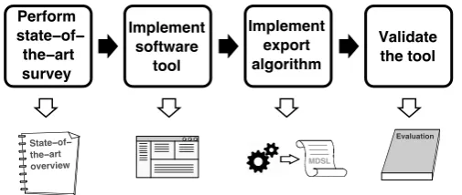
In order to achieve the formulated research objective, a number of activities had to be performed. This section lists these activities and describes how they relate to each other. A visual overview of these steps is given in Figure 1.4.
16 Introduction MDSL State−of− the−art overview Perform state−of−
[image:16.595.199.452.124.231.2]the−art survey Implement software tool Implement export algorithm Validate the tool Evaluation
Figure 1.4: The research approach for this project.
can be used in a tool that supports the creation of mappings between two ontologies.
2. Implement a software tool that supports the creation of map-pings between two ontologies. Such a tool enables the user to cre-ate meaningful mappings between entities in the ontologies. The exact requirements for the mapping tool have been derived from the work of Stanislav Pokraev [17].
3. Implement an algorithm that creates transformations based on the resulting ontology mappings. The mappings that were defined using the tool that was created in step 2 can now be used in order to derive transformations. In this step, an algorithm was developed that can create these transformations. These transformation describe how data from one ontology must be manipulated in order to map to the second ontology.
4. Validate the tool by performing a case study, using the Purchase Order Mediation scenario as context for this study. The case study served to demonstrate the use and evaluate the tool. This evaluation shows how the tool contributes to achieving the research objective, and to identify opportunities for further improvements.
1.5 Structure of this thesis
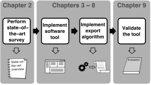
In order to report on the design and execution of this research, the following structure is used in the remainder of this report. Figure 1.5 shows how the structure of this thesis corresponds to the research steps that are outlined in the previous section.
Chapter 2 gives an overview of related work and the state-of-the-art in ontol-ogy matching algorithms and mapping tools. This provides an overview of existing solutions for automating the mapping between ontologies.
1.5 Structure of this thesis 17
Chapter 2
Chapters 3
−
8
Chapter 9
MDSL
State−of− the−art overview
Perform state−of−
the−art survey
Implement software
tool
Implement export algorithm
Validate the tool
[image:17.595.144.404.126.272.2]Evaluation
Figure 1.5: Structure of this thesis
Chapters 4–7 present the development iterations that led to the implementa-tion of the mapping tool, including a descripimplementa-tion of the design and imple-mentation details.
Chapter 8 presents the final resulting architecture and design of the tool. The chapter shows the result of the combined work described in the previous chapters.
Chapter 9 presents the results of a case study of the tool. This chapter shows how the tool is used in the process of solving the integration problem and presents an evaluation of the tool.
Chapter 10 presents a discussion on this research and the implemented map-ping tool.
Chapter 2
State-of-the-art in ontology
mapping
This chapter presents an overview of existing work on the topic of ontology matching. The types of work that are considered can roughly be divided into two separate categories: matching algorithms and mapping tools. It is convenient to make this distinction, because both types of work have a different influence on this research. Studying this work provides a good overview on the possibilities and challenges of ontology matching.
In the literature study [23], this state-of-the-art overview has been worked out. This chapter presents a summary and conclusion of the study, for the sake of clarity and completeness.
2.1 Ontology mapping algorithms
In the literature study, several ontology mapping algorithms have been reviewed. These are algorithms that have been engineered with the purpose of creating mappings between two ontologies. So when two ontologies are similar, but not identical (for example, they describe the same domain), a matching algorithm can try and generate mappings that allow instances of one ontology to be trans-formed into instances of the other ontology.
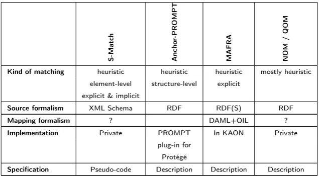
The algorithms that have been reviewed are S-Match [9], Anchor-PROMPT [2, 14], MAFRA [13], NOM [7], and QOM [6]. For each of these algorithms, the following characteristics have been determined and evaluated. First, the
2.2 Ontology mapping tools 19
schema or ontology elements. Explicit techniques rely on tools such as thesauri or ontologies that explicitly codify semantic information.
Next, thesource formalism for the algorithms is discussed. It is the ‘input’ for the algorithm. Some algorithms will accept any XML schema, others may only work with some proprietary description of the schema or ontology.
The third characteristic is the mapping formalism. This is the ‘output’ of the algorithm. The mapping formalism specifies what the result of the algorithm will be. Some may output their results as XSLT, XQuery, or other transformations. Others may use the input formalism as output formalism, or they may use some proprietary format or description for describing the mappings.
Another characteristic of interest is theimplementation. This is a rather straight-forward point: for each algorithm, the question is answered whether there is an implementation of this algorithm available.
Finally, it is determined whether a specification of the algorithm is available. Of course, some level of specification is available in the articles or other sources that describe the algorithm, but how deep does this go? Some articles may only describe the basic functioning of the algorithm, while others may go as far as listing the entire source code or pseudo code for the algorithm.
As mentioned before, the literature research report [23] provides a more detailed discussion on each of the evaluated algorithms. A summary of this research is given in table 2.2.
S-Match Ancho
r-PROMPT
MAFRA NOM
/
QOM
Kind of matching heuristic heuristic heuristic mostly heuristic element-level structure-level explicit
explicit & implicit
Source formalism XML Schema RDF RDF(S) RDF
Mapping formalism ? DAML+OIL ?
Implementation Private PROMPT In KAON Private plug-in for
Protégé
[image:19.595.113.431.430.605.2]Specification Pseudo-code Description Description Description
Table 2.2: Comparison of ontology mapping algorithms
2.2 Ontology mapping tools
20 State-of-the-art in ontology mapping
techniques that can be used in practice. Tools that exist today usually do not include an intelligent matching algorithm. Rather, they provide a rich graphical user interface that makes it as easy as possible for a user to create mappings from one ontology to the other.
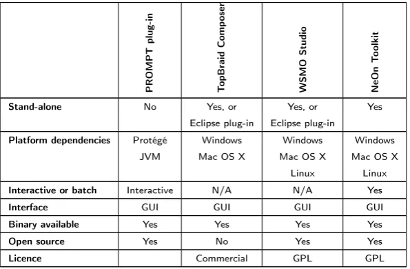
The tools that have been evaluated in the literature research report are the PROMPT plug-in for Protégé [2], TopBraid Composer1, WSMO Studio2, and
the NeOn Toolkit3 . In order to evaluate these applications, a list of
charac-teristics has been created, just like with the evaluation of the algorithms. For the evaluation of the tools, the first characteristic was to see whether it is a
stand-alone application, or a plug-in to an existing program. Knowing if a tool is stand-alone or not is an interesting characteristic, because it provides you with a better feel of what the tool looks like. This in turn makes it easier to decide whether the tool can be used as inspiration for developing the ontology mapping tool, with regard to the user interface, the benefits or drawbacks of either a stand-alone or plug-in based tool, etc. Of special interest are tools that are implemented as Eclipse plug-ins. The ontology mapping tool will eventu-ally be integrated with other tools that have been developed by the Telematica Instituut. All these existing tools have been implemented as Eclipse plug-ins, and the ontology mapping tool will also be implemented as an Eclipse plug-in. Therefore, knowing whether the tool or algorithm that is being evaluated is an Eclipse plug-in might help in the decision of using it when implementing the mapping tool.
Next, the application is checked for platform dependencies. Some tools may run on Microsoft Windows only, others may need a Java Virtual Machine, etc. If the tool is implemented as a plug-in for another application, this is also a required dependency. Again, knowing this characteristic helps to get a better overall picture of the tool. If the tool provides code or functionality that could be copied one-on-one to the ontology mapping tool, knowing the dependencies is crucial, since these dependencies may then also be required for the ontology mapping tool.
Next, it is worth checking out if the tool operates ininteractive or batchmode. Some tools may work in a batch mode: one needs to specify the inputs to map and the tool will generate mappings in a burst. Other tools may use a more interactive approach, getting intermediate feedback or additional input from the user. Depending on the mapping algorithm that the ontology mapping tool will perform, either of these modes of operation — and their implementation in various tools — may be useful. Having a number of implemented examples at hand while designing the tool may offer some inspiration.
The next characteristic discusses theinterface of the tool. Some tools may have only a user interface, be this in the form of a command-line input / output system, a full-fledged GUI, or something similar. Others may offer an API, offer their services as a Web service, as some other TCP/IP-based service, or as something entirely different. If the tool is suitable for use in / with the ontology mapping tool, knowing the interface is a necessary requirement to incorporate
1http://www.topbraidcomposer.com
2http://www.wsmostudio.org
2.2 Ontology mapping tools 21
it into the tool. If this is the case, the specification of the interface (such as API specification, WSDL description, etc.) has to be available.
Finally, theavailability of the tool is determined. This answers some practical questions about the licenses for the tool, whether or not it is open source, the availability of binaries, installers, source code, etc. Knowing whether the tool is open source or not may be beneficial. If it is, parts of the source code may be re-used in the ontology mapping tool, if the tool provides some interesting functionality. Having the binary available makes it much easier to compare the tool to others, or, if so desired, include it in or use it in combination with the ontology mapping tool.
The literature research report gives a complete evaluation of the aforementioned tools, based on these characteristics. A summary of this evaluation is given in table 2.4.
PROMPT
plug-in
T
opBraid
Comp
oser
WSMO
Studio
NeOn
T
oolkit
Stand-alone No Yes, or Yes, or Yes
Eclipse plug-in Eclipse plug-in
Platform dependencies Protégé Windows Windows Windows JVM Mac OS X Mac OS X Mac OS X
Linux Linux Interactive or batch Interactive N/A N/A Yes
Interface GUI GUI GUI GUI
Binary available Yes Yes Yes Yes
Open source Yes No Yes Yes
[image:21.595.124.422.314.509.2]Licence Commercial GPL GPL
Chapter 3
Development Iterations
Now that the motivation and background for developing the ontology mapping tool is clear, it is time to formulate concrete requirements for the tool, and then to design and implement it. Numerous approaches and methodologies exist for this, ranging from very rigid, sequential processes such as the waterfall model or formal methods, to very flexible and iterative processes, such as the various agile methodologies.
Each of these approaches has its strengths and weaknesses, and the characteris-tics of the project determine which approach is best suitable. For the develop-ment of the ontology mapping tool within the scope of this Masters assigndevelop-ment, the following characteristics are considered:
1. The exact requirements are subject to change.
There are several reasons for this. First, the implementation of certain requirements may lead to new insights and generate new ideas for the ap-plication, that were not considered before. Second, the exact capabilities and limitations of the underlying software platform (the Eclipse platform, the Eclipse Modeling Framework, and possibly other resources) with re-gard to handling ontologies and in particular the OWL language are not very well known in advance. This might cause the requirements to change a little for practical reasons. Third, others within the Telematica Instituut are working on different but related aspects of the SWS Challenge. Their research and findings may also lead to new insights, that have an impact on the requirements of this mapping tool.
2. The development time required is hard to determine up front.
As stated before, it is not very clear in advance what the capabilities and limitations of Eclipse, EMF, and possibly other libraries are with regard to dealing with ontologies and OWL. Also, having to learn how to develop Eclipse plug-in applications and how to work with the EMF framework takes some time that is hard to estimate. All these factors make it very hard to come up with an accurate project planning.
23
in such methodologies. Therefore, an iterative approach is adopted. In each iteration, a selected subset of the requirements is chosen to be implemented, and a working, running implementation of this is delivered.
Starting the iterative development
Before the first iteration, a meeting was held to determine the initial set of
user stories. This is a term that is used in agile practices such as eXtreme Programming (XP). It describes one particular thing that the application can do for a user. They are in the format of about three sentences of natural text. It is similar to a usage scenario, but without regard for user interface specific details. In some cases, there may be the need for more specifics than what can be captured by three sentences of natural text. If this is so, these details are provided through interviews with the ‘customer’ (in this case, the involved project members at the Telematica Instituut) and recorded as notes or annotations to the user story.
This first set of user stories is by no means definitive, but it serves as a start-ing point for the first iteration. From this initial set of user stories, a subset is selected for implementation in the first iteration. After this first iteration, another subset is chosen for the subsequent iteration, but in the mean time, stories might have been added, altered or removed altogether.
Because of this iterative approach, the concrete formulation of requirements and the prioritizing and planning of them, can be distributed over time. This makes it very much suitable for changing requirements and an unsure development speed.
The set of implemented user stories Although, in true XP projects, user stories are almost never put into formal documentation, they are nevertheless listed in the box below for the sake of illustrating the development process. This is the set of user stories that have eventually been implemented.
Implemented user stories
Visualizing an ontology
The tool should be able to visually display an existing ontology, that is stored as an EMF representation of an OWL ontology.
Use visual tree-representation of EMF editor
Test/research what OWL editor to use:
• EMF editor based on OWL Ecore model
24 Development Iterations
Load and display two ontologies
The tool should be able to load two ontologies from file (see story Visualizing an ontology) and display both of them visually in the same Eclipse perspective.
Indicate relations between ontology-entities
The user should be able to indicate that an entity from the first input ontology is related to an entity from the second input ontology. The user can specify as much of these 1-to-1 relations as he wishes.
Specify relations
The user should be able to give a more specific description of a previously indicated relation between two entities. (For example, specifying that a relation is an equivalence relation, or disjoint, etc.).
Edit relations
Once a user has created relations, he should be able to edit these. This means that the user must be able to change either the ‘source’ entity, the ‘target’ entity or the type of relation.
Save the mappings
The user must be able to save the mappings in a file, such that the relations that the user specified are stored an can be re-opened at a later time.
Opening a saved mappings-file
A user must be able to open a previously saved mappings-file. The appropriate ontologies and specified mappings are subsequently presented to the user.
Automatically inferring mappings
Based on the two input ontologies, the tool must be able to automatically infer mappings using some algorithm. These must then be visualized to and be editable by the user.
25
Constraints
There are a number of constraints and assumptions that have to be considered. These are the initial constraints that have been documented:
A reasoner for EMF representations of OWL models is available with the Eclipse platform or one of its plug-ins.
The application is to be build as a plug-in to the Eclipse platform.
The tool should deal with the input (and possibly the output) in form of EMF model repositories, in order to tie in with other tools that are developed in the context of developing a mediator for the SWS Challenge.
More of a ‘hint’ than a constraint: use as much existing plug-ins as possible to create the functionality for the tool
The input for the tool is available in the form of EMF representations of OWL models.
The following sections describe the iterations that make up the development process. Each section describes the following information about an iteration:
Goals Describes the specific goals of the iteration. What should have been accomplished when this iteration has been completed?
User stories This describes the user stories that are implemented in that spe-cific iteration, which make sure that the specified goals are reached.
Design This section describes the design of the application for this specific iteration.
Solutions and decisions This describes the problems that were encountered while implementing the user stories of this iterations, and the relevant solutions and decisions that have been made in order to solve these prob-lems.
Chapter 4
Iteration 1
Starting the project
4.1 Goals
The main goal of this iteration is to provide a starting point for the rest of the development of the application. The iteration itself only delivers the results of one user story, but it provides the opportunity to setup a work environment and to get familiar with a number of tools and software frameworks that are needed throughout the implementation process.
After implementing the user story in this iteration, code is generated that can serve as a basis for further development of the ontology mapping tool. This code allows for working with OWL models in the context of Java code and the Eclipse environment.
4.2 User stories
Visualizing an ontology
The first user story that was chosen to be implemented is described as follows:
The tool should be able to visually display an existing ontology, that is stored as an EMF representation of an OWL ontology.
4.2 User stories 27
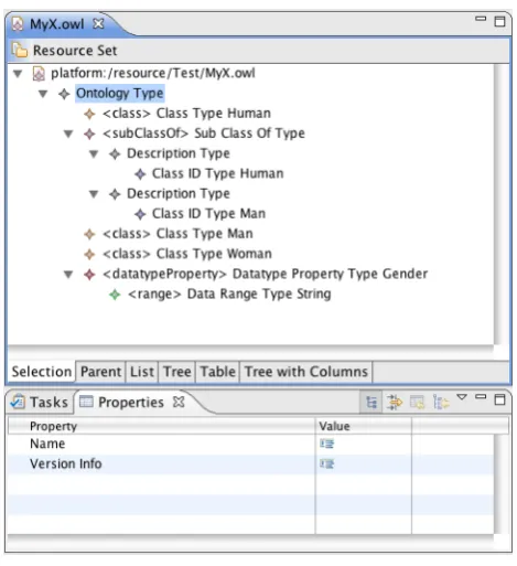
[image:27.595.156.391.211.468.2]Implementing this user story consists of a single step: using the capabilities of EMF to automatically generate the executable code for displaying an OWL ontology. The resulting product is a fully functional, runnable Eclipse plug-in that is capable of not only displaying, but also editing OWL files. This is all displayed as a tree view, with menu bar controls and context-menus that offer the means for editing the file. See also Figure 4.1.
Figure 4.1: The OWL editor that is generated using the EMF framework.
There are several reasons for using EMF for this task. The framework offers all the facilities needed to manipulate models, such as OWL models, using Java code. Based on a single model specification, the framework can generate code to read, manipulate, create, and store instances of such a model. This means that is not necessary to deal with the syntax of OWL, or to handle and write text-based XML files. Rather, the only thing necessary is to provide EMF with an OWL model specification, and then only short Java code is required to manipulate the model.
Other frameworks and libraries exist that offer similar functionality. One such example is Jena1, which is also used in later iterations. Even so, EMF is
pre-ferred over these alternatives. The reason for this is mostly to be compatible with other applications that have been (or will be) developed for the SWS Chal-lenge. Eventually, all these tools may get integrated into one single toolkit. This integration is easiest when all individual tools are written for the same platform (Eclipse), and use the same libraries and frameworks (EMF).
28 Starting the projectIteration 1
4.3 Design
In subsequent iterations, it is very interesting to see how the design of the application evolves with the addition of more and more functionality. However, in this iteration a description of the design is not very interesting. There are two reasons for this. First, the design is an automatically generated one, so nothing can be said about design decisions, use of software patterns, etc. But second, most importantly, most of the code that was created will be discarded in later iterations.
To understand the design of the system, and see which generated code is useful and which can be discarded, let’s first take a look at the EMF framework and its function.
Making use of the Eclipse Modeling Framework
(EMF)
The EMF is a set of plug-ins for the Eclipse IDE. It provides a number of tools for modeling and automatic generation of code based on a structured data model. All that EMF needs is a specification of the model. The code that is generated are Java classes for the model, adapter classes that allow for easy editing and viewing of the model, and a basic editor for creating and manipulating documents that conform to this model.
The specification of the model that EMF requires, can be in various forms. It can be annotated Java interfaces, XML Schema, UML Class Diagrams (support for Rational Rose is built in), or XMI documents. Using this model specification as input, EMF generates two documents: an Ecore model and a generator model. Ecore is the meta-modeling language of EMF. It is a XMI document, that is used to describe application data models. The generator model is used to specify information that is needed for code generation, but that is not included in the Ecore model, such as: where should the code be generated, what is the plug-in ID for the generated application, etc.
Using the EMF generator and a sub-part of EMF, the EMF.Edit Framework, we can now generate the Java code for creating, manipulating, and viewing documents that conform to the specified model. The framework generates a number of items, among which:
Java interfaces For each class in the model, a Java interface is generated. This interface can be extended if needed, by manually changing or adding new methods.
4.4 Solutions and decisions 29
A factory EMF generates a factory interface and implementation. This factory is used to create instances of model classes.
A package EMF generates package interface and implementation. This pack-age provides some static constants and methods for accessing the model’s metadata.
ItemProviderAdapterFactory This class is used to create the item providers that are used to work with the model code.
ItemProviders For each class in the model, an ItemProvider is generated. These ItemProviders provide all methods that are needed to support the standard viewers, commands, etc.
Editor An standard editor is created that can be run as an Eclipse plug-in. ModelWizard Using this ModelWizard, new files of the model’s type can be
created. They can then also be edited using the generated Editor.
For a more in-depth overview of the framework, see the The Eclipse Modeling Framework (EMF) Overview [1] in the Eclipse documentation.
4.4 Solutions and decisions
EMF was used to implement (or actually, auto-generate) the code for this iter-ation. The generic editor that is generated by EMF, based on a model of OWL, is in fact an implementation that conforms to the user story. The following outlines the steps that were taken to obtain this editor.
Find an OWL specification
EMF can generate model code and the editor, based on a specification of the model. This means that we need such a model specification of the OWL lan-guage. This specification is available from the W3C website [11]. It is an XML Schema definition (XSD) file containing the specification for OWL DL.
A note on the OWL specification
30 Starting the projectIteration 1
the mappings that the ontology mapping tool produces may be stored in OWL itself, rather than in some other format.
However, since this iteration is only about displaying an OWL ontology and compatibility or persistency issues are not yet considered at this point, it suffices to simply choose OWL 1 DL. The reason for not immediately choosing OWL 1.1 anyway, is that at the time of implementing this iteration, it was still unclear whether there would be enough tool support for OWL 1.1. In particular, a reasoner needs to be available that supports it, since the ontology mapping tool will very likely make use of such a reasoner.
Create the models for the OWL specification
Using the New EMF Project Wizard, a new Eclipse project is created, based on the OWL DL specification. After finishing the wizard, the Ecore model and the generator model have automatically been created.
Generate the code
Using the generated models, EMF can now generate all the model and editor code. After this step, the editor is a separate project in Eclipse and can be run as an Eclipse plug-in. This is, in fact, the implementation for the first user story.
4.5 Evaluation
The main goal of this iteration was to provide a starting point for the devel-opment of the rest of the application. This has succeeded, in that the process of creating this iteration was a good way to get familiarized with the appro-priate tools and technologies. The basis — in terms of gained knowledge and implemented code — is now there to continue development on the mapping tool. The quality of the generated editor, however, is not as sophisticated as most OWL editors that are used by other tools. The three main different entities of an OWL model — classes, properties and individuals — are usually represented in three different views. See for example the screenshot of the Protégé tool in Figure 4.2. The generated editor does not do this, it lists them all in the same single tree view.
4.5 Evaluation 31
The shortcomings of this generated editor will be solved in later iterations. The user interface of this editor will be discarded in iteration 2 in favor of a GUI that can display two ontologies at the same time. Dividing the tree viewer into three separate views, for the three different types of entities, is therefore not relevant for this iteration.
Another limitation is the use of a tree for representing ontologies. In an OWL ontology, the classes are ordered hierarchically, as are the properties. All classes are a subclass of the OWL class Thing, and classes can be arranged in a subclass / superclass hierarchical structure. The same is true for properties. But when displaying the relations between classes, as defined by the properties, a tree is not the best way to do this, since the resulting model is not necessarily a tree. This is illustrated by the Wine ontology2 as explained in section 5.4.2.
Never-theless, a tree representation is chosen for the implementation of the mapping editor. A compelling reason for this is that the EMF framework uses trees to visually represent models. By using the EMF framework, you get the visual tree representation of the model ‘for free’. The drawback is, as explained, that this tree does not have the expressive power to represent structures in an OWL ontology that are not hierarchical. However, since the mapping editor is con-cerned with creating mappings between elements in an ontology and not with visualizing an ontology as concisely and effectively as possible, this drawback does not outweigh the benefits of using the EMF framework.
Chapter 5
Iteration 2
Relate two ontologies
Now that iteration 1 has provided some insight into the technology, and some code to work with, it is now possible to start building more functionality into the application. This chapter describes the second iteration, which focuses on relating two ontologies using the mapping tool.
5.1 Goals
This iterations has two main goals. The first is to extend the results of the previous iteration by making it possible to display two ontologies instead of one. The obvious reason for this is that the tool should map between two ontologies, so having those two displayed on screen instead of just one at the time, makes it much easier to create mappings.
The second goal is to add mapping functionality. While the goal here is mostly to provide very basic mapping functionality, this iteration does provide a solid basis for further extending the mapping capabilities of the application.
5.2 User stories
In order to reach the goals of this iteration, the following two user stories will be implemented.
Load and display two ontologies
5.3 Design 33
The tool should be able to load two ontologies from file (see story Visualizing an ontology) and display both of them visually in the same Eclipse perspective.
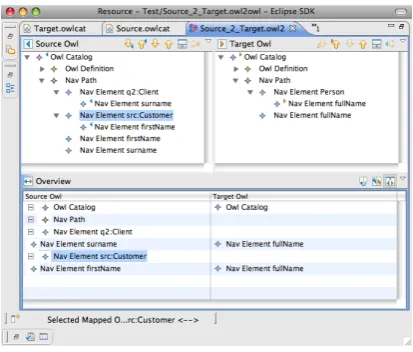
[image:33.595.170.377.241.417.2]The ontologies are again visualized as tree diagrams, in the same way as for the story in the first iteration. The tree controls should be positioned next to each other, so that controls for creating mappings can be placed in between or below them. The implementation of this user interface is displayed in figure 5.1.
Figure 5.1: The mapping editor
Indicate relations between ontology-entities
This is the first in a series of user stories that add the actual mapping function-ality to the application. This particular story starts the development of these functions by allowing the user to indicate that relations exist between entities of the two ontologies. The story is formulated as follows:
The user should be able to indicate that an entity from the first input ontology is related to an entity from the second input ontology. The user can specify as much of these 1-to-1 relations as he wishes.
As is obvious from the story description, this functionality is minimal. Only indicating a relation is possible, but what kind of relation this is, cannot yet be specified. The next iteration will extend the capabilities of the application with more powerful mapping capabilities.
5.3 Design
34 Relate two ontologiesIteration 2
ontologies and mappings, etc. Creating this from scratch as an editor for the Eclipse platform would be quite a large task. However, there is a component in the EMF framework that can provide most of this functionality. This compo-nent is in the package org.eclipse.emf.mapping.ecore2ecore. It is a basic mapping editor that allows for the creation of mappings between two ecore models. Basic as it may be, it has all the features required for this iteration, except that is uses ecore models instead of OWL files as its input.
In order to display OWL files using this editor, they first need to be converted to ecore models. The ecore model that was developed for this purpose is described in section 5.3.1.
5.3.1 The OwlCat file format
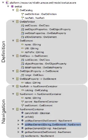
If the existing ecore2ecore mapping editor is to be used, the OWL files that are used as the input for the mapping editor, have to be converted to an ecore model. A metamodel for these ecore models has been created called OwlCat (originally short for OWL Catalog). Figure 5.2 gives an overview of this metamodel. The top-most class in this model is theOwlCatalogclass. From this point in the class hierarchy on, the OwlCat metamodel is basically split into two parts. One part deals with representing the original OWL file in terms of EMF classes, attributes, and relations. This means that OWL Classes as defined in one of the original OWL files are copied one-on-one to an OwlClass in the OwlCat file. Likewise, object and data properties in the original OWL file are also copied to
OwlObjectPropertyand OwlDataPropertyclasses, respectively.
The other part of the OwlCat metamodel hierarchy deals with visually repre-senting the OWL file. The Solutions and Decisions section will go into more detail as to why this separation between the definition of the OWL model and its visual representation is necessary.
5.3.2 The conversion process
Using the existing ecore2ecore mapping editor and the OwlCat model that is defined in the previous section, the entire process for displaying the OWL files in the mapping editor can now be described. It is a four-step process. First, each OWL file needs to be read from the file system. These files are the original OWL files, serialized using XML as usual, describing the two input models for the mapping application. Second, the Jena1 libraries are used to make Java
representations of these OWL files. We now have the two complete ontologies in memory as Java objects. Third, two OwlCat models are created. These OwlCat models are ecore models, the format that is required by the editor to display the ontologies. It is easy to create these models in this step, because all information about the OWL models is represented using the Java objects that were generated by Jena. If this had been omitted, all information had to be read and interpreted line by line from the OWL files, which is quite a complicated job. All this is now handled by Jena. The fourth step is to load the newly
5.3 Design 35
36 Relate two ontologiesIteration 2
[image:36.595.152.500.170.240.2]created OwlCat models into the editor, where they are displayed in the two tree viewers. Figure 5.3 summarizes this process.
Figure 5.3: The conversion process
After changing the code of this editor so that it can handle OWL files, the code is now structured in several separate projects. These projects are:
nl.telin.amuse.owl This project contains all the code to represent OwlCat files. The code is automatically generated by the EMF framework, based on the OwlCat ecore model.
nl.telin.amuse.owl.editor This project contains the code for creating an OwlCat editor. The code is automatically generated by the EMF frame-work based on the OwlCat ecore model.
nl.telin.amuse.owl.mapping.owl2owl This is the same kind of project as nl.telin.amuse.owl, it is automatically generated code to deal with Owl2Owl models. It is based on the Owl2Owl ecore model. This Owl2Owl model is an adapted form of the ecore2ecore model of the EMF editor. It specifies how the mappings between the two models are structured. A more detailed description of this mapping model can be found in section 6.3.1.
nl.telin.amuse.owl.mapping.owl2owl.editor Similarly, this project contains an editor for Owl2Owl models. It is also based on the Owl2Owl ecore model.
nl.telin.amuse.owl.owl2emf This project contains the code that is nec-essary to convert the original OWL files to the OwlCat EMF models that are the required input for the mapping editor.
nl.telin.amuse.owl.pelletjena This project contains the libraries for the Jena and Pellet projects. The Jena libraries are used to convert the OWL files to Java objects. The Pellet project is a reasoner that is used to infer additional information from the ontologies.
Most of the code in the above project is library code, automatically generated code, or part of the existing ecore-to-ecore mapping editor. A number of items are worth mentioning separately though.
5.4 Solutions and decisions 37
using Jena, to an OwlCat EMF model. When the convert method of this class is invoked, the method will first load the OWL file and convert it to an
OntModel, the root object that is used by Jena to represent ontology models using Java objects. Then, an empty OwlCat model is created using the code that was generated by the EMF framework. Finally, the method will copy all classes, all object properties, and all data properties from the Jena Java objects to the OwlCat model. The OwlCat model is written to the disk so it can later be loaded in to the mapping editor.
The ConvertToOwlCatActionDelegate class In this iteration, the con-version process that is described above is not executed automatically when the user tries to load the OWL files into the editor. The user first has to explicitly convert the input OWL files to OwlCat files, and can then load the latter into the editor. For this reason, a context menu option is added to the user inter-face. When the user invokes the context menu (by default by right-clicking) on an OWL file, a command is available to convert this file to OwlCat. The
ConvertToOwlCatActionDelegateclass contains the code that is executed when this command is invoked.
Thenl.telin.amuse.owl.mapping.owl2owl.testpackage This is a package in thenl.telin.amuse.owl.mapping.owl2owl.editorproject that contains a JUnit2 test case for theOwl2EmfConverter class. The test
case makes sure that the functionality of the converter class is as required, and also serves as a ‘description in code’ of how to use and invoke the converter.
5.4 Solutions and decisions
5.4.1 Alter the editor or convert the input
For the implementation of the user stories in this iteration, the existing editor code from the EMF framework was adopted instead of creating all necessary code from scratch. This makes a more or less complete user interface already available for use, as well as the underlying code to deal with mappings between two models. It does however introduce the need to alter the editor, so that it can deal with OWL files instead of ecore models. In order to accomplish this, two options are possible. The first is to completely rewrite the internal workings of the editor, such that it can work with OWL files directly. The second is to keep the internal workings largely intact, but convert the OWL files to ecore models, and feed those to the editor.
Initially, the first option might seem like the most direct approach. However, rewriting the editor so it can handle OWL files is a very complicated task and would require a large amount of time and coding effort. The second option introduces an extra step to the process, which unnecessarily complicates the process, especially when the user has to be aware of this step and take action (i.e. the user has to give theconvertcommand before he can load the OWL files
38 Relate two ontologiesIteration 2
OWL
Altered Editor
OWL
Ecore Mapping Editor
Owl Cat
[image:38.595.178.467.123.348.2]XML Java
Figure 5.4: Two options for creating the editor
into the editor). Nevertheless, this options has been chosen since the amount of time and coding effort required to implement this is much less compared to the first option. This makes it possible to devote more time to other functionalities of the application.
Another advantage of this second method is that it separates the mapping func-tionality that is provided by the editor from the details of the input format. This separation is achieved by first converting the input format (OWL) to an intermediate format (OwlCat). The editor can now easily be adapted to map other formats than just OWL files. The only thing that needs to be written is an adapter from the other input format (such as Java classes or some XML schema) to the intermediate OwlCat format.
5.4.2 Avoid infinite loops caused by circular references
5.4 Solutions and decisions 39
Region
AdjacentRegion Problem: model contains circular references:
Editor tries to load entire model in a tree:
Region
AdjacentRegion : Region AdjacentRegion : Region
AdjacentRegion : Region
AdjacentRegion : Region
[image:39.595.185.363.145.227.2]AdjacentRegion : Region....
Figure 5.5: The infinite-loop problem of the ecore2ecore mapping editor
To solve this infinite loop problem, two solutions are possible. The first solution is to stop the editor from trying to traverse the entire tree, or to tell it to skip a branch as soon as it detects recursion. The other solution is to make sure that no circular references exist in the input models. Since the code of the ecore2ecore mapping editor is rather complex, the first solution is not an attractive one. Technically it is possible, but it requires a lot of effort to determine exactly how, where, and when the editor executes the tree traversal code. Therefore, the second solution is chosen. This solution is illustrated in Figure 5.6 and explained below.
As mentioned in section 5.3.1, the OwlCat meta-model that is used to describe the input models for the mapping editor contains two main parts: the “defini-tion” part for describing the original OWL input file and the “naviga“defini-tion” part for displaying the ontology. The definition part may contain circular references. Since this part is not used to display the ontology, this poses no problem. The key to the solution is to use elements from the navigation part to describe ele-ments from the definition part, in such a way that this navigation part willnot
contain circular references. This navigation part is then used to generate the tree representation from. The following steps illustrate this procedure:
1. When first loading an OwlCat file, aNavElementclass is created for each top-level class and property in the “definition” part of the OwlCat model. ThisNavElementclass only contains a reference to theOwlElementit represents, not to any children that thisOwlElementmight have. 2. When the mapping editor then tries to load the entire model, it sees only
40 Relate two ontologiesIteration 2
Solution
2. Editor loads entire model, but this now only contains two NavElements
NavElement (Region)
NavElement (AdjacentRegion)
1. Create NavElement for each element in the model
Region
AdjacentRegion
NavElement
NavElement
3. When the user expands a list item, a new NavElement is created
NavElement (Region)
NavElement (AdjacentRegion) NavElement (AdjacentRegion)
NavElement
AdjacentRegion
[image:40.595.170.485.471.638.2]NavElement
5.5 Evaluation 41
elements in the tree. For example, he can select a class and expand only that class. At this point, newNavElementsare created for the subclasses and properties of the selected class. These NavElement classes contain references to theOwlElementclasses they represent, and to their parent
NavElement.
When the user re-opens the mapping file, the editor wants to traverse the entire tree. However, the tree only goes as deep as the user expanded the elements in the first place. A circular reference is never encountered, and the editor displays the root elements of the ontology, as well as all sub-elements that the user had previously expanded.
5.5 Evaluation
The first of the two goals for this iteration was to make an editor that can display two ontologies. This is accomplished nicely by using the existing EMF editor code and adapting it to the needs for the mapping application. As seen in the screen shot in figure 5.1, the interface supports exactly what the user story describes.
The second goal was to add mapping support to the editor. This has also been accomplished by using the EMF editor, and creating the conversion code so that it can handle OWL files.
Chapter 6
Iteration 3
Create meaningful mappings
At this point, the mapping editor can load OWL files, convert them to the intermediate OwlCat format, display two ontologies side-by-side and support the creation of relations between two ontology entities. This iteration will refine the mapping capabilities of the editor, such that the relations between two ontology entities can be expressed with much greater and accurate detail.
6.1 Goals
The previous two iterations laid the foundation for the ontology mapping ap-plication. But as the name suggests, the main purpose of the application is to enable the creation of meaningful mappings between two ontologies. Based on the now created application foundations, the actual mapping functionality is implemented in this iteration.
The goal is to implement all required features for creating mappings between on-tologies. These features include both the user interface and the underlying code. The user interface should allow the user to create mappings and describe these mappings in a meaningful way. The underlying code should be able to represent these mappings in the internal model of the application, so that later iterations can use this for further extension of the functionality, such as persisting the mappings or adding more automation to the mapping process.
6.2 User stories
Specify relations
6.2 User stories 43
related. This is an important step towards creating more meaningful mappings. The description of this user story is the following:
The user should be able to give a more specific description of a previously indicated relation between two entities.
This ‘specific description’ consists of a number of items. The user must be able to enter all of these items into specific fields on the user interface. For each relation, the following information must be recorded:
Mapping Name The user must be able to specify a name for this mapping.
Source Element The path that identifies the source element in this mapping relation, which is an OWL Class or Property from one of the two input ontologies. The path is automatically determined by the mapping editor, based on the element that the user has selected in the tree representation of the ontology.
Target Element The path that identifies the target element in this mapping relation, which is an OWL Class or Property from the other input ontology. The path is automatically determined by the mapping editor, based on the element that the user has selected in the tree representation of the ontology.
Relation Function In some situations, some operations needs to be performed in order to map classes or properties. For example, in order to map the property first name andsurnameto the propertyfull name, one can imagine that a function such as concatenateis to be executed for this relation. Using this field, the user can specify the name of the function that is to be executed. This functionality is explained in more detail in section 6.3.1 on the next page.
Function Argument Index In the previous example, the order of the proper-ties is important. The propertysurnameis to be append to the property
first name, not the other way around. The Function Argument Index is used to specify the order in which the properties are processed by the specified Relation Function.
Edit relations
This story makes the application more user friendly. It allows the user to edit the relations that have been specified. This means that when a mapping needs to be altered, the user does not have to delete it and create a new one, but can instead edit the existing one to make it correct. The user story is described as follows:
44 Create meaningful mappingsIteration 3
6.3 Design
6.3.1 The owl2owl mapping meta-model
[image:44.595.209.406.299.544.2]The ecore2ecore mapping editor that forms the basis of the owl2owl mapping editor makes use of the EMF framework for both its input and its output. The input is defined by the OwlCat meta-model, and describes the two OWL ontologies that need to be mapped. Similarly, the output is defined by the owl2owl meta-model. This model extends the Mapping meta-model that is used by the ecore2ecore mapping editor. It defines the classes and attributes that are necessary to describe all required mapping information that is described in the user story Specify Relations.
Figure 6.1: The owl2owl mapping model
The owl2owl meta-model is presented in Figure 6.1. The class OwlMapping
contains all the attributes that are required to store the information that is described in the user story. As described in the user story, the Relation Function field must indicate the function that is to be called when the mappings are processed. This information is indicated by therelationFunctionattribute. Its value is of typeOwlMappingRelationType, which is an enumeration that describes which functions are available. At this iteration, it is not yet clear which exact functions will be available. Three functions are likely to be required anyway, so these have been added by default. These are the equalsfunction (the two mapped entities are completely equal to each other), the partOf
function (one entity is a part of the other entity, one can e.g. imagine an entity
6.4 Solutions and decisions 45
6.3.2 Editing the mapping information
[image:45.595.138.409.262.381.2]Now that the mapping model is defined, the editor needs an interface that provides the user with the means to supply and edit this information. The EMF framework and the existing ecore2ecore mapping editor provide most of this functionality. The user sees this functionality in the form of the Properties view (Figure 6.2) in Eclipse. This is a view that displays the mapping information of the selected mapping. Within this view, the user can also directly edit the mapping information.
Figure 6.2: The Properties view of the owl2owl mapping editor
A convenient feature of the mapping editor and the EMF framework is that the contents of the Properties view is built directly from the owl2owl mapping model and the user-defined mappings. When the underlying mapping model changes, the EMF framework can update the supporting Java code and the Properties view automatically reflects these changes. During development, this occurred frequently, so not having to manually update the editor each time the model changed saved time and effort. After development, it can be expected that the set of Relation Functions will have to be changed or expanded. This is now eas-ily achieved by changing the OwlMappingRelationType enumeration, and having EMF update the Java files, and it will be automatically reflected by the editor.
6.4 Solutions and decisions
6.4.1 Storing the information
46 Create meaningful mappingsIteration 3
Implementing a custom mapping format
In order to store the required mapping information, it is possible to devise a custom mapping file format. An XML Schema that was considered to store the mappings is listed below. The information that is represented by this schema does not exactly match that which is expressed in the user story and represented in the final owl2owl mapping model, because this schema was devised early on in the development process, when the exact details and requirements were still subject to change.
<?xml version="1.0" encoding="UTF-8"?>
<schema targetNamespace="http://www.telin.nl/Mapping" elementFormDefault="qualified"
xmlns="http:/