Abstract—The influence of the contactor angle, gas inlet diameter, particle diameter, length of the draft tube and height of the entrainment zone on the average cycle time in a novel conical spouted bed dryer with a draft tube has been analyzed by a two-level factorial experimental design to optimize the drying process at low temperature. The effect of these factors has been determined by a statistical analysis. An empirical correlation to calculate average cycle time in a novel conical spouted bed dryer with a draft tube has been proposed.
Index Terms—conical spouted beds, cycle times, draft tube, experimental design
I. INTRODUCTION
Spouted bed technology in conical geometry of the contactor is very useful for applications where a vigorous movement of the solids is required, as happens in the handling of solids that are sticky, of irregular texture and with a wide particle size distribution [1-6]. Moreover, the conical spouted bed is successful for waste treatment, especially biomass wastes [3, 5-7] mainly because avoids the stickiness and particle segregation and for drying of granular materials and sludge [8-11]. In spite of the versatility of the spouted beds, there are situations in which the gas-solid contact is not fully satisfactory due of the bed instability. The insertion of a draft tube in a conventional spouted bed overcomes the limitations of the spouted for improving gas-solid contact. The good performance for conventional applications (drying, granulation, and coating) and for those of a more recent nature is due to the cyclic movement of particles and to the versatility in the properties related to solid circulation (such as the time required by a particle to complete a cycle and the fractions of this time spent in the spout and the annular zones).
Manuscript received April 14, 2011; revised April 19, 2011. This work was supported Spanish Ministry of Science and Innovation (Project TRA2009-0318 and Project CTQ2010-18697) and of the Ministry of the Basque Country (Project SA-2010/00097).
M. J. San José is with the Departamento de Ingeniería Química, Universidad del País Vasco, Aptdo 644. 48080 Bilbao, Spain. (corresponding author to provide phone: 946015362; fax: 34-946013500; e-mail: [email protected]).
The insertion of a draft tube in a conventional spouted bed overcomes the limitations of the spouted for improving gas-solid contact. Several advantages of using a draft tube in a conventional spouted bed are the following [12-15]: greater flexibility in the operation; lower gas flow and pressure drop; solids of any size or nature may be treated; narrower residence time distribution; better control of solid circulation; avoids maximum spoutable bed height. Consequently, solid circulation may be controlled by changing independently column diameter, stagnant bed height or particle diameter. Among the disadvantages the following are worth mentioning: lower mixing degree; complexity of design; risk of tube blockage; lower contact between gas and solids; lower heat and mass transfer; longer recirculation time.
Bed stability of conical spouted beds with a non-porous draft tube located at the bottom of the contactor has been studied in a previous paper [16] and the ranges of the geometric factors of the conical contactor, of the non-porous draft tube and of the contactor-particle system for stable operating condition have been established in order to become the stability. As cycle time distribution is influence by the inner draft tube, in order to study the effect of different geometrical factors and operating conditions on the average cycle time in conical spouted bed with a non-porous draft tube, an experimental study has been carried out at different stable operating conditions in beds drying in diluted spouted bed regime
Particle circulation has been qualitatively described in the literature by using different parameters. Among these parameters, the following are worth mentioning: particle trajectories [17-22], particle velocity in the spout and annular zones [17, 23-24] and particle cycle times [17-18, 25-30]. Cycle time is the time spent by a particle in traveling the annulus and spout and returning to the fountain.
From the results obtained in the studies on cycle times, the importance of experimental conditions is noteworthy. Thus, the contactor base angle [17, 25], particle diameter [31-32], stagnant bed height, and gas inlet [26] all influence the cycle time. Roy et al. [27] determined that the average cycle time is independent of the bed level.
In this paper, a two-level factorial experimental design is carried out in order to analyze the influence of the contactor
Modelling of Analysis of Influence Parameters
on Cycle Time in a Novel Conical Spouted Bed
Dryer with a Draft Tube
necessary to apply to thermal sensitive materials. II. EXPERIMENTAL
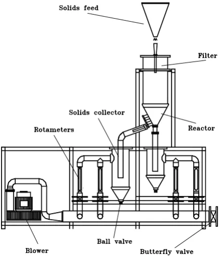
The hydrodynamic study has been carried out at in a combustor at a range of temperatures between 25 and 1000 ºC in beds consisting of beach sand and beach sand polluted with oil spill. The experimental unit designed at pilot plant scale, shown in Figure 1, basically consists of two blowers that supplies a maximum flow rate of 500 Nm3h-1 at a pressure of 15 kPa, an electric resistance for preheating the air, thermocouples for measuring the temperature at several positions in the contactor and two high efficiency cyclones in order to collect the ashes and fine particles. The air flow rate is measured by means of three rotameters, and by means of two mass flow meters controlled by computer. The accuracy of this control is 0.5% of the measured flow rate [33].
Conical contactors made of poly(methyl methacrylate) have been used. Figure 2 shows the geometric factors of these contactors, whose dimensions are as follows: column diameter, Dc, 0.36 m; contactor angle, , between 28 and 45°; height of the conical section, Hc, from 0.60 to 0.36 m; gas inlet diameter, Do, in the range of 0.03-0.06 m. The values of the stagnant bed height, Ho, are in the range between 0.05 and 0.35 m. Operation has been carried out at the minimum spouting velocity and at velocities 20 and 30% above this value.
With the aim of studying the influence of the device in average particle cycle time (in the same experimental conditions), the study has been carried out by inserting centrally a draft tube in the contactor.
The draft tube, Figure 2, is a cylindrical tube made of poly(methyl methacrylate) located centrally at the bottom of the contactor. The diameter of the draft tube, dd, was determined for a viewpoint of stability of spouting and was varied from 0.03 m to 0.05 m [9]. The choice of the upper limit of the draft tube diameter, dd, was made based on to the average spout diameter,Ds, which is between the gas inlet diameter, Do, and the base diameter, Di, and in conical spouted beds is nearer to the base diameter, Di [9]. The entrainment zone, distance between the base of the contactor and the lower base of the device, hd, is in the range 0.01-0.09 m [9]. This range has been determined experimentally for a viewpoint of the clogging of solid particles used. The length of the draft tube, ld, is in the range 0.02-0.34 m [9].
The solids studied are glass spheres, which corresponds basically to the D group of the Geldart classification [34-35] and their properties are set out in Table 1.
The distribution of cycle times has been measured by monitoring a colored particle using an image treatment system composed of a camera, a video recorder, a monitor with tactile screen, and the computer support needed for treatment of the data obtained. The cycle time, Figure 3, namely, the time spent by a particle in traveling the annulus and spout and returning to the fountain, has been determined by freezing the image where the particle is seen again in the fountain after one cycle.
[image:2.595.55.273.288.542.2]The cycle time is calculated by counting the frames between two consecutive appearances of the particle in the fountain and taking into account that the time between two frames is 1/25 s. The frequency of the cycles described by a colored particle has been determined in all of the experimental systems, by means of equipment for the acquisition and treatment of video images. The number of cycles considered in each system is always above 1000. Fig. 2. Geometric factors of the contactor and of the draft tube.
Average cycle time has been calculated from the distribution of cycle times by the following expression:
n
1 i i i n
1 i i i i c
t f
t f t
t (1)
In order to optimize the drying process at low temperature, as it is necessary to apply to thermal sensitive materials, the influence of the contactor angle, gas inlet diameter, particle diameter, length of the draft tube and height of the entrainment zone on the average cycle time in conical spouted bed with a draft tube has been analyzed by a two-level factorial experimental design.
The five variables analyzed have been chosen based on the variables that have influence in the calculation of average cycle time in conical spouted beds without draft tube and in previous experimental observations that indicates the possible significant effect of the variables of the draft tube. These five factors have been varied at two levels by a 25 factorial experimental design, totalizing N= 32 experiments or operating conditions combinations.
glass beads 1 and 5 mm; length of the draft tube diameter 0.02 and 0.11 m and the height of the entrainment zone 0.01 and 0.09 m.
Table I summarizes the geometric factors of the conical contactors, the dimensions of the central draft tubes and particle properties of solids studied.
III. RESULTS
The design matrix of the 32 experiments is shown in Table 2. This table lists the 32 runs, with each row representing one of the runs, the experimental conditions of each run and the results of average cycle time obtained at each experimental condition. In Table I, variables 1, 2, 3, 4 and 5, represent contactor angle, gas inlet diameter, Do, particle diameter, dp, length of the draft tube, ld, and height of the entrainment zone, hd, respectively. The low level of each factor is setting by –and the high level by +.
The number of effects and interactions of a factorial design is calculated by eq. 2 and for a factorial design 25 there are five main effects, ten two-variable interactions, ten three-variable interactions, five four-variable interactions and one five-variable interactions.
)! i k ( ! i
! k ni
[image:3.595.133.222.51.222.2] (2)
[image:3.595.51.287.563.718.2]Fig. 3. Schematic diagram of particle states in a conical spouted bed dryer with a draft tube in spouted bed regime.
TABLE I
GEOMETRIC FACTORS OF THE CONTACTORS AND OF THE DRAFT TUBE AND PARTICLE PROPERTIES
Contactor poly(methyl methacrylate)
Column diameter Dc (m) 0.36 Contactor angle (deg) 28 and 45 Height of the conical section Hc (m) 0.60, and 0.36 Gas inlet diameter Do (m) 0.03 and 0.05 Stagnant bed height Ho (m) 0.20
Draft tube poly(methyl methacrylate)
Inside diameter dd (m) 0.04, Tube length ld (m) 0.02 and 0.11 Distance of entrainment zone hd (m) 0.01 and 0.09
Particle (Glass beads)
Diameter dp (mm) 1 and 5 Density p (kg/m3) 2420
TABLE II
DESIGN MATRIX AND EXPERIMENTAL RESULTS OF AVERAGE CYCLE TIME
Run Mean 1 2 3 4 5 ct
1 + - - - 11.75
2 + + - - - - 14.76
3 + - + - - - 22.95
4 + + + - - - 22.95
5 + - - + - - 3.934
6 + + - + - - 4.94
7 + - + + - - 7.682
8 + + + + - - 9.646
9 + - - - + - 24.67
10 + + - - + - 30.98
11 + - + - + - 48.18
12 + + + - + - 60.5
13 + - - + + - 8.26
14 + + - + + - 10.37
15 + - + + + - 16.13
16 + + + + + - 20.25
17 + - - - - + 11.13
18 + + - - - + 13.97
19 + - + - - + 21.73
20 + + + - - + 27.29
21 + - - + - + 3.72
22 + + - + - + 4.68
23 + - + + - + 7.27
24 + + + + - + 9.13
25 + - - - + + 23.36
26 + + - - + + 29.34
27 + - + - + + 45.62
28 + + + - + + 57.28
29 + - - + + + 7.82
30 + + - + + + 9.82
31 + - + + + + 15.27
main effect or interaction column, by adding the result to produce a contrast, and then by dividing the contrast by one-half the total number of runs in the experiment [36]. The effect estimates are computed from:
1 k N
1
i ( )
c ) ( c
2 t t
Effect
(3)
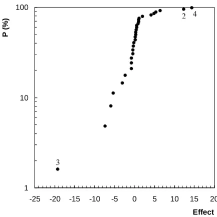
An appropriate method for estimating the importance of effects and interactions is the normal probability scale [37]. The normal probability of the 31 ordered effects (main effects and interactions) obtained is plotted in Figure 4. The effects that are negligible are normally distributed with mean equal to zero and fit to a straight line, while the significant effects have non-zero means and do not fit the straight line [36]. As it is observed in Figure 4 the most of the effects fit well on a straight line. Nevertheless, the main effects 1, 2 and 4 are significant because do not fit the straight line.
Normal plotting of the residuals provides a diagnostic check for any tentatively entertained model. The regression model used to obtain the predicted values is:
4 3 5
2
4 3
2 1
c
x x 66 . 3 x x 70 . 2
x 17 . 7 x 5 . 9 x 18 . 6 x 05 . 2 5 . 19 tˆ
(4)
where x1, x2, x3, x4 represent 1, 2, 3 and 4 factors, respectively and x2x5 and x3x4 represent 25 and 34 interactions. x1, x2, x3, x4 and x5 take the value -1 or +1 according to the columns of signs in Table II.
The residuals for the 32 runs at that design point are summarized in Table IV. The normal probability of the residuals indicates that except for 1, 2, 3 and 4 factors are explained by random noise.
From the effects of the factors, the significance order of the factors is analyzed and it is observed that the factor of greatest influence on average cycle time is particle diameter and as its effect is negative means that as particle diameter is increased average cycle time decreases. The following factor is length of the draft tube. As the effect of length of the draft tube is positive, an increasing in length of the draft tube maximize average cycle time and gas inlet diameter maximize average cycle time as the effect is positive. Moreover, angle of the contactor and height of the entrainment zone have a slight influence on average cycle time.
1 10 100
-25 -20 -15 -10 -5 0 5 10 15 20
Effect
P (
%
[image:4.595.323.540.57.274.2])
Fig. 4. Normal probability of the effects. TABLE III
MAIN EFFECTS OF VARIABLES AND INTERACTIONS ON AVERAGE CYCLE TIME
Effects Values
Main 1 4.10
2 12.35
3 -19.27
4 14.34
5 -0.71
Two-variable interactions 12 1.07
13 -3.09
14 1.95
15 0.25
23 -5.97
24 4.87
25 5.41
34 -7.33
35 0.17
45 -0.75
Three-variable interactions 123 1.12
124 0.88
125 0.33
134 -2.39
135 -0.31
145 0.99
234 -5.33
235 -0.19
245 0.62
345 0.56
Four-variable interactions 1234 -0.75
1235 -0.35
1245 -0.38
1345 6.41
2345 0.43
Five-variable interactions 12345 0.37
3
[image:4.595.60.284.90.513.2]From the influence of the factors on average cycle time, the variables have been grouped in terms of the dimensionless moduli that are commonly used to characterize the hydrodynamic properties in spouted beds. The experimental results of average cycle time for all of the experimental systems studied have been fitted by the Complex method for nonlinear regression of optimization Box [38] to the following equation expressed. The regression coefficient of all the experimental data is r2= 0.97 and the maximum relative error is below 7%.
1 . 0
o d o 07 . 1
o d o 31 . 1
i o 68 . 0
i p 48 . 0
c H
h H H
l H D D D
d 4 . 2
t
(5)
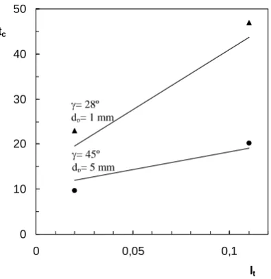
[image:5.595.336.534.61.265.2]The good agreement of the experimental values of average cycle time in drying is shown in Figure 5. I this Figure the experimental values of average cycle time (points) and calculated ones (lines) have been plotted against the length of draft tube at different particle diameter, due to the major factors on average cycle time are particle diameter and length of the draft tube.
IV. CONCLUSION
Major influence parameters of a novel conical spouted bed with draft tube on cycle time for drying process time are obtained by varying the levels of the influence factors using a two-level factorial experimental design.
The factor of major influence on average cycle time is particle diameter followed by length of the draft tube and gas inlet diameter. A decrease in particle diameter and an increase in length of the draft tube and gas inlet diameter give way to an increase in average cycle time. Influence of angle of the contactor and height of the entrainment zone on average cycle time is not as noticeable.
Analysis modelling results are verified, by using this experimental design, through some experimental drying times at room temperature at different cycle times and input parameters for optimum drying time are achieved.
NOMENCLATURE
Db, Dc, Di, Do diameter of the top diameter of the stagnant bed, of the column, of the bed bottom, and of the bed inlet, respectively, m
dd diameter of the draft tube, m dp particle diameter, m
fi cycle time frequency Ho height of the stagnant bed, m hd height of the entrainment zone, m ld length of the draft tube, m
c
t , tc, ti average cycle time and cycle time corresponding to the frequency fi, s Greek Letters
0 10 20 30 40 50
0 0,05 0,1
lt tc
Fig. 5. Average cycle time vs. length of the draft tube. Experimental values (points), calculated values (lines). Experimental systems: = 28, 45º; Do= 0.05m, Ho= 0.20 m, ht= 0.01 m.
TABLE IV
RESIDUALS OF VARIABLES AND INTERACTIONS ON AVERAGE CYCLE TIME
y yˆ y-yˆ
11.75 12.64 -0.89 14.76 16.74 -1.98 22.95 19.6 3.35 22.95 23.7 -0.75 3.934 0.96 2.97 4.94 5.06 -0.12 7.682 7.92 -0.24 9.646 12.02 -2.37 24.67 34.3 -9.63 30.98 38.4 -7.42 48.18 41.26 6.92
60.5 45.36 15.14 8.26 7.98 0.28 10.37 12.08 -1.71 16.13 14.94 1.19 20.25 19.04 1.21 11.13 7.24 3.89 13.97 11.34 2.63 21.73 25 -3.27 27.29 29.1 -1.81
3.72 -4.44 8.16 4.68 -0.34 5.02 7.27 13.32 -6.05 9.13 17.42 -8.29 23.36 28.9 -5.54 29.34 33 -3.66 45.62 46.66 -1.04 57.28 50.76 6.52 7.82 2.58 5.24 9.82 6.68 3.14 15.27 20.34 -5.07
= 28º dp= 1 mm
[image:5.595.63.282.72.388.2]ACKNOWLEDGMENT
This work was carried out with the financial support of the Spanish Ministry of Science and Innovation (Project TRA2009-0318 and Project CTQ2010-18697) and of the Ministry of the Basque Country (Project SA-2010/00097).
REFERENCES
[1] M. Olazar, M.J. San José, A.T. Aguayo, J.M. Arandes and J. Bilbao, “Hydrodynamics of sawdust and mixtures of wood residues in conical spouted beds”, Ind. Eng. Chem. Res., vol. 31, pp. 1784-1791, 1992. [2] M. Olazar, M.J. San José, F.J. Peñas, A.T. Aguayo and J. Bilbao,
“The Stability and Hydrodynamics of Conical Spouted Beds with Binary Mixtures”, Ind. Eng. Chem. Res., vol. 32, 2826-2834, 1993. [3] M. Olazar, M.J. San José, R. Llamosas and J. Bilbao,
“Hydrodynamics of sawdust and mixtures of wood residues in conical spouted beds”, Ind. Eng. Chem. Res., vol. 33, pp. 993-1000, 1994. [4] M.J. San José, M. Olazar, F.J. Peñas, and J. Bilbao, “Segregation in
Conical Spouted Beds with Binary and Tertiary Mixtures of Equidensity Spherical Particles”, Ind. Eng. Chem. Res., vol. 33, 1838-1844, 1994.
[5] M.J. San José, S. Alvarez, R. Aguado and J. Bilbao, “Combustión de serrín y residuos agroforestales en lechos de borboteo cónicos (Conical Spouted Beds)”, Inf. Tecnol., vol. 13, no. 2, pp. 127-131, 2002.
[6] M.J. San José, S. Alvarez, M.A. Izquierdo and A. Ortiz de Salazar, “Fluidodinámica de los lechos de borbor cónicos (spouted beds) para el tratamiento de residuos plásticos”, Inf. Tecnol., vol. 13, no. 5, pp. 21-24, 2002.
[7] M.J. San José, S. Alvarez, A. Ortiz de Salazar, A. Morales and J. Bilbao, “Treatment of Cork Wastes in a Conical Spouted Bed Reactor”, Int. J. Chem. React. Eng., vol. 4, A15, pp. 1-7, 2006. [8] H. Altzibar, G. López, M.J. San José, S. Alvarez and M. Olazar,
“Drying of Fine Sand in a Pilot Plant Unit Provided with a Draft-Tube Conical Spouted Bed”. Chemical Engineering Transactions, vol. 11, pp. 725-730, 2007.
[9] H. Altzibar, G. López, S. Alvarez, M.J. San José, A. Barona, and M. Olazar, “A Draft-Tube Conical Spouted Bed for Drying Fine Particles”, Drying Technol., vol. 26, pp. 308-314, 2008.
[10] M.J. San José, S. Alvarez, A. Morales, L.B. López and A. Ortiz de Salazar, “Diluted spouted bed at high temperature for the treatment of sludges wastes”, Chemical Engineering Transactions, vol. 20, pp. 303-308, 2010.
[11] M.J. San José, S. Alvarez, A. Ortiz de Salazar, A. Morales and J. Bilbao, “Shallow spouted beds for drying of sludge from the paper industry”, Chemical Engineering Transactions, vol. 21, pp. 145-150, 2010.
[12] R.H. Buchanan and, B. Wilson, “Fluid-Lift Solids Recirculator”, Mech. & Chem. Eng. Transactions, vol. 1, no. 1, pp. 117-124, 1965. [13] J.R. Muir, F. Berruti and L.A. Behie, “Solids Circulation in Spouted
and Spout-Fluid Beds with Draft Tubes”, Chem. Eng. Commun., vol. 88, pp. 153-171, 1990.
[14] R.K. Konduri, E.R. Altwicker, M.H.III. Morgan, “Atmospheric Spouted bed Combustion: the Role of Hydrodynamics in Emissions Generation and Control”, Can. J. Chem. Eng. vol 73, no. 5, pp. 744-754, 1995.
[15] T. Ishikura, H. Nagashima and M. Ide, “Hydrodynamics of a Spouted Bed with a Porous Draft Tube Containing a Small Amount of Finer Particles”, Powder Tehnol., vol. 131, pp. 56-65, 2003.
[16] M.J. San José, S. Alvarez, A. Ortiz de Salazar, M. Olazar and J. Bilbao, “Operating Conditions of Conical Spouted Beds with a Draft Tube. Effect of the Diameter of the Draft Tube and of the Height of Entrainment Zone”, Ind. Eng. Chem. Res., vol. 46, pp. 2877-2884, 2007.
[17] B. Thorley, J.B. Saunby, K.B. Mathur and G.L. Osberg, “An Analysis of Air and Solids Flow in a Spouted Wheat Bed”, Can. J. Chem. Eng., vol. 37, pp. 184-192, 1959.
[18] T. Robinson and B. Waldie, “Particle Cycle Times in a Spouted Bed of Polydisperse Particles”, Can. J. Chem. Eng., vol. 56, 632-625, 1978.
[19] C. Sullivan, A. Benkrid and H. Caram, “Prediction of Solids Circulation Patterns in a Spouted Bed”, Power Technol., vol. 53, pp. 257-271, 1987.
[20] A. Benkrid and H. Caram, “Solid Flow in the Annular Region of a Spouted Bed”, AIChE J., vol. 35, pp. 1328-1336, 1989.
[21] B.D. Hook, H. Littman and M.H. Morgan III, “A Priori Modelling of an Adiabatic Spouted Bed Catalytic Reactor”, Can. J. Chem. Eng., vol. 70, pp. 966-982, 1992.
[22] M. Cassanello, F. Larachi, R.Legros and J. Chaouki, “Solids Dynamics From Experimental Trajectory Time-Series of a Single Particle Motion in Gas-Spouted Beds”, Chem. Eng. Sci., vol. 54, no. 13-14, pp. 2545-2554, 1999.
[23] D. Van Velzen, H.J. Flam, H. Langenkamp and A. Casile, “Motion of Solids in Spouted Beds”, Can. J. Chem. Eng., vol. 52, pp. 156-161, 1974.
[24] G.C. Suciu and Patrascu, M.H., “Phase distribution and residence time in a spouted bed”, AIChE J., vol. 23, pp. 312-318, 1977.
[25] H.A. Becker, “An Investigation of Laws Governing the Spouting of Coarse Particles”, Chem. Eng. Sci., vol. 13, pp. 245-262, 1961. [26] B. Waldie and D. Wilkinson, “Measurement of Particle Movement in
a Spouted Bed Using a New Macroprocessor Based Technique”, Can. J. Chem. Eng., vol. 64, pp. 944-949, 1986.
[27] D. Roy, F. Larachi, R. Legros and J. Chaouki, “A Study of Solid Behaviour in Spouted Beds Using 3-D Particle Tracking”, Can. J. Chem. Eng., vol. 72, pp. 945-952, 1994.
[28] M.J. San Jose, M. Olazar, M.A. Izquierdo, S. Alvarez, J. Bilbao, “Solid Trajectories and Cycle Times in Spouted Bed”. Ind. Eng. Chem. Res., vol. 43, no. 13, 3433-3438, 2004.
[29] C. Seiler, P.J. Fryer and J.P.K Seville, “Statistical modelling of the spouted bed coating process using positron emission particle tracking (PEPT) data”, Can. J. Chem. Eng., vol. 86, no. 3, pp. 571-581, 2008. [30] Z. Wenqi, Z. Yong and J. Baosheng, “Novel method to study the
particle circulation in a flat-bottom spout-fluid bed”, Energy Fuels, vol. 24, pp. 5131-5138, 2010.
[31] A. Chaterjee, “Effect of Particle Diameter and Apparent Particle Density on Internal Solid Circulation Rate in Air-Spouted Beds”, Ind. Eng. Chem. Process Des. Dev., vol. 9, pp. 531-540, 1970.
[32] N. Piccinini, A. Bernhard, P. Campagna, F. Vallana, “Segregation Phenomenon in Spouted Beds”, Powder Technol., vol. 18, pp. 171-178, 1977.
[33] M. Olazar, M.J. San José, S. Alvarez, A. Morales and J. Bilbao, “Design in Conical Spouted Beds for the Handling of Low-Density Solids”, Ind. Eng. Chem. Res., vol. 43, pp. 655-661, 2004.
[34] D. Geldart, “Types of Gas Fluidization”, Powder Technol., vol. 7, no. 5, pp. 285-292, 1973.
[35] D. Geldart, Gas Fluidization Technology, New York: John Wiley, 1986.
[36] D.C. Montgomery and G.C. Runger, “Applied Statistics and probability for engineers”, 3rd ed., New York: John Wiley & Sons, 2003
[37] C., Daniel, Applications of statistics to industrial experimentation, New York: Wiley, 1976.