©IJRASET: All Rights are Reserved
383
Jaya Algorithm Based Automatic Generation
Control of Two Area Load Frequency Control with
Nonlinearities
Kavita Sharma1, Kapil Parikh2
1
M.tech Scholar Electrical Engineering SITE, Nathdwara, India
2
Assistant Professor Electrical Engineering SITE, Nathdwara, India
Abstract: In a complex power system, often two or more areas are interconnected to each other for having the mutual benefits of peak load supply, reliability of supply, increase in reserve capacity and diversity factor etc. For a proper operation interconnected powers system it is of utmost importance to have constant frequency and tie line power exchange. To manage the changes and keeping record of it, in each area uses Automatic Generation control (AGC) is provided. The difference between the load side demand and the generation at the moment is Area Control Error (ACE). The AGC in each area is carried out by a controller. In the present piece of work to regulate AGC Proportional Integral Derivative (PID) controller is installed in each area. It is one of the conventional methods. For enhancing the performance of controller in the past many optimization techniques have been involved. To name some of it are, hybrid Firefly Algorithm and Pattern Search (hFA–PS) technique, Bacteria Foraging Optimization Algorithm (BFOA), Genetic Algorithm (GA) and conventional Ziegler Nichols (ZN) which are separately based on PI or PID controller.
The use of very new technique in this field has been made here which is JAYA algorithm. It is partly based on Artificial Intelligence. To optimize the PID controller Integral Time multiply Absolute Error (ITAE) as objective function is utilized. Under different loading conditions, system parameters of controller are changed to test its sensitivity. Also, it variation of time constants for speed governor, turbine and tile line power were considered here under the Generation Rate Constraint(GRC) values of ±0.05 and ±0.025. While performing all these analysis certain definite constraints are considered such as time delay, reheat turbine, and GRC. The typical GRC for a thermal power plant lies between 2% and 5% per minute. Later it was compared with the conventional and several other techniques to evaluate its performance particularly conventional ZN controllers, GA PID controller and BFOA PID controller. The proposed system model has been developed using the platform provided by the MATLAB/SIMULINK.
Keywords: Automatic Generation Control (AGC), Jaya Algorithm, Load frequency control, Sensitivity analysis, Two area system
I. INTRODUCTION
©IJRASET: All Rights are Reserved
384
same level whenever there is change. This type of AGC is called as Load Frequency Control (LFC). This problem has been addressed several times in the past and still being addressed with the better solution each time. From traditional ways of controlling via only simple controllers only like Proportional (P), Proportional Integral (PI) and Proportional Integral Derivative (PID) to methods where these controllers are further modified to give better results[6]. The modification has been incorporated using many optimization techniques such as Genetic Algorithm (GA), Neural Network (NN), fuzzy logic Genetic Algorithm (GA), Particle swarm optimization (PSO) or Bacteria Foraging Optimization Algorithm (BFOA) etc. Also some recently used developed optimization techniques too like hybrid Firefly Algorithm (FA) and Pattern Search (PS) or Teaching learning Based Optimization Technique (TLBO). But the present work has taken very newly developed techniques inspired by TLBO named as JAYA Algorithm (JA)[4]. The system which has been outlined as discussed so far has been developed and realized using the platform provided by the MATLAB/SIMULINK. The two area non reheat interconnected system has been analyzed by utilizing this software tool with different load conditions under variable system parameters.
II. SYSTEM MODELING
Fig.1 shows two area non reheat thermal power systems and their rating are 2000 MW (area-1 and area-2) with a nominal load of 1000 MW. Two area non-reheat thermal system is extensively used in the literature for design and investigation of automatic load frequency control of interconnected areas [25]. Fig.1 shows different parameter classifies as B1& B2-frequency bias parameters; ACE1 & ACE2 -area control errors; u1&u2 -control outputs from controller; R1 &R2 - governor speed regulation parameters(p.u.); TG1 &TG2-speed governor time constants(seconds); ∆PV1 &∆PV2 -change in governor valve positions (p.u.); ∆PG1& ∆PG2 -governor output command (p.u.); TT1 & TT2 - turbine time constant(seconds); ∆PT1 & ∆PT2 - change in turbine output powers;
∆PD1 & ∆PD2-load demand changes; ∆Ptie -incremental change in tie line power (p.u.); KP1 &KP2 -power system gains; TP1 &TP2 - power system time constant(seconds); T12 - synchronizing coefficient and ∆F1 &∆F2 -system frequency deviations(Hz). The generation of power by Thermal power plants can be modified or changed at a specific maximum rate (2-5% per min) and this is Generation Rate Constraint (GRC). Both areas of the power system consist of the speed governing system, turbine and generator. Both areas have three inputs and two outputs. The inputs are the controller input ∆Pref (also denoted as u), load disturbance∆PD
and tie-line power error ∆Ptie the outputs are the generator frequency ∆F and Area Control Error (ACE).
Power System
+
+
+
+
ACE1 ∆F1
ACE2 ∆F2
PID Controller ∑ ∑ ∑ ∑ ∑ ∑ PID
Controller ∑ ∑ ∑
Power System Turbine with GRC
Controller
Controller Governor
Turbine with GRC
+ _ + _ + _ + _ _ + _ _ + _ U1
∆PG1
∆PD1
∆PT1
∆P12
∆Ptie
∆PD2
U2
∆PG2
∆P21 ∆PT2
α α + _
Fig.1 Two area non-reheat thermal plant consideration of with GRC [1]
= ∆ +∆ (1) where, B is the frequency bias parameters.
The turbine is represented by the transfer function
( ) =∆ ( )
∆ ( )= (2) The transfer function of
a governor is given in (2) as above.
( ) =∆ ( )
∆ ( )= (3)
The speed governing system has two inputs ∆Pref and ∆ with one output ∆PG(s) given as in (4),
∆ ( ) =∆ ( )− ∆ ( ) (4)
©IJRASET: All Rights are Reserved
385
( ) = (5)
Where, KP=1/D and TP =2H/FD
The generator load system has two input ∆PT(s) and ∆PD(s) with one output ∆F(s) is specified by (6) and referred to [22],
∆ ( ) =∆ ( )[∆ ( )− ∆ ( )] (6)
III. JAYA ALGORITHM
A. Introduction
There are several algorithms for optimizing in case of different problems. These are mostly categorized as evolutionary based and swarm intelligence based. Some of the examples are Genetic algorithm (GA), Differential Evolution (DE), Particle swarm optimization (PSO), Ant Colony Optimization (ACO), Artificial Bee Colony (ABC), Fire Fly (FF) algorithm and many more like these. The criterion for the optimization is to work with control parameters as these are probabilistic. Some algorithm like GA, DE may use parameters more specific to terms of the algorithm i.e. algorithm specific parameters. Therefore, in case of such algorithm it is important to tune the algorithm specific control parameters carefully. Any error in tuning would cause the computational work to increase and may result in the local optimal solution. Taking account of this very point an algorithm that does not uses algorithm specific parameters for control is developed for example it uses population size and generation number as the controlling parameters. This algorithm was developed in 2011 and named as teaching learning-based optimization (TLBO). Development of this algorithm has leaded the new algorithm which has only one phase of operation instead of two as in TLBO. Also, due to this it is very simple. Its working is different form TLBO and is known as Jaya Algorithm (JA)[1]. Fig.2 shows the flow chart of Jaya Algorithm.
B. Description
Let,,f(x)= objective function to be minimized i= iteration
j= designed variables
m= number of designed variables (j=1, 2,…, m) k= population size
n= number of candidate solution (k=1, 2…, n)
©IJRASET: All Rights are Reserved
386
It assumed that there are two types of candidates exist i.e. best and worst where best candidates acquires the best value of f(x) (f(x)b). On the other hand worst candidate acquire the worst value for f(x) (f(x)w) in the pool of whole solution of candidates.
Above is the flow chart description Jaya Algorithm. Where it has each and every step involved in the process of deciding optimal solution from the given set of population.
Let it be ithiteration. Here, kth candidate jth variable= Xj,k,i (value)
The above value of variable is modified as for ith iteration within [0,1],
, , = , , + , , , , − , , − , , , , − , , (7)
where,
, ,=Best candidate value of jth variable , ,= Worst candidate value of jth variable , ,= , ,‘s modified value
, ,, , ,= nay tow arbitrary number for jth variables
, , , , − , , =represents inclination of solution towards best solution
− , , , , − , , = represents affinity of solution to evade worst solution
If the , , has the better value than the , ,, then it will be maintained and treated as the input to the next iteration.
The concept of above algorithm is very simple. As, in every iteration it will always tend to put effort to acquire the best solution while getting away from the worst solution. Hence, it can be said that the algorithm will achieve victory on getting the best solution which its name Jaya, Sanskrit word synonymous to victory[4].
C. Objective Function
The objective function, here for the designing of controller, there are certain criterions to follow. The criterion used here is the Integral of Time multiplied Absolute Error (ITAE). It was observed that ITAE use in AGC is better option as an objective function.
J = ITAE =∫ (|∆F | + |∆F | + |∆P |). t. dt (8)
Where,
∆F & ∆F = change in system frequency
∆P = Change in the power of tie line (increasing change), t = simulation time
While designing PID controllers it is restricted by certain constraints too. Hence, the given problem is expressed as, For minimizing the function J, the following constraints bound it,
K ≤K ≤K , K ≤K ≤K , K ≤K ≤K (9)
IV. RESULTANDDISCUSSION
The systematic study with different cases as dynamic response analysis with SLP in area-1,area-2, area-1 and area-2 simultaneously & sensitivity analysis with parameter variations for TG, TT, T12. The influence of the proposed JA based PID controller has been verified by comparing the results with some newly published heuristic optimization techniques such as the BFOA, GA and conventional ZN based PID controllers same kind of system. Table 1 shows value of different parameters of KP, Ki, Kd at different algorithm as BFOA, GA, conventional ZN and JA at Generation rate constraint ± 0.05 & ± 0.025[26]
TABLE: 1
Controller parameters for different cases
Controller parameters
Conventional Controller (ZN)
GA PID Controller
BFOA PID Controller
JAYA PID Controller GRC = ± 0.05 GRC = ± 0.025 Kp 0.5865 0.0955 0.1317 2.5279 0.001
©IJRASET: All Rights are Reserved
387
A. Analysis of Results And DiscussionThe proposed JA is compared with other conventional approaches suggested in and heuristic techniques such as ZN, GA and BFOA as shown in table 2 from which it is clear that with same PID controller structure, the saturation limit (GRC = ±0.05), objective function, least ITAE values is obtained with proposed JA (ITAE = 00.10617) compared to BFOA (ITAE = 0.4788), GA (ITAE = 0.5513) and ZN (ITAE = 0.6040) techniques. Hence, it can be concluded that the proposed Jaya algorithm better the conventional ZN technique and heuristic techniques GA, BFOA as least objective function cost is obtained with the proposed Jaya algorithm. Therefore, superior system performance in term of minm conditions least settling times in frequency and tie-line power deviations is achieved with proposed Jaya optimized PID controller compared to others.
TABLE: 2 Settling time and error
Techniques
GRC = ± 0.05 GRC = ± 0.025 Settling time Ts (Sec.) Performance
indices Settling time Ts (Sec.)
Performance indices
ΔF1 ΔF2 ΔPtie ITAE ΔF1 ΔF2 ΔPtie ITAE
Proposed JAYA 2.7 2.8 3.2 0.10617 5.3 3.7 7.1 0.462 BFOA 4.7 6.4 5.1 0.4788 9 7.9 8.3 1.5078
GA 6.9 8 5.7 0.5513 11.1 11.2 11 2.4668 ZN 8.1 9.2 6.7 0.604 15.3 14.1 15.3 3.4972
B. Dynamic Response Analysis
To understand the dynamic response of the system given below different Step Load Perturbation (SLP) and GRC values, the subsequent cases are considered. Table-3 shows the controller parameters for different cases.
1) Case (i): Step load perturbation in area-1 with saturation limit (GRC = ±0.05)
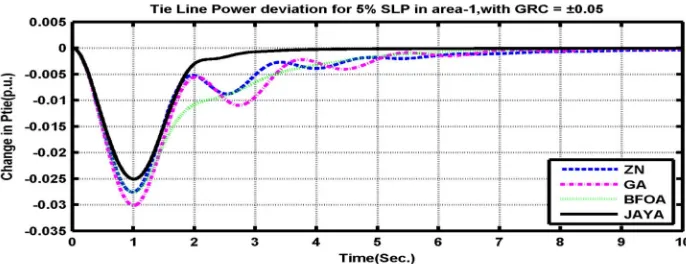
Fig.3-5 show Frequency deviation of area-1, area-2, & tie line power deviation of 5% SLP applied in areas-1 at t=0 with GRC=±0.05. It is clear from Fig. 3–5, the proposed Jaya algorithm optimized PID controller shows best dynamic performance compared to ZN, GA, BFOA optimized PID controllers.
Fig.3 Frequency deviation of area-1for 5% SLP in area-1 with GRC=±0.05
©IJRASET: All Rights are Reserved
388
Fig.5 Tie line power deviation for 5% SLP in the area-1, with GRC=±0.05
[image:6.612.124.494.297.420.2]2) Case (ii): Step load perturbation in area-1 and area-2 simultaneously with saturation limit (GRC = ±0.05)
[image:6.612.126.491.448.582.2]Fig.6-8 show frequency deviation of area-1for 5% SLP in area-1 and 2% SLP in the area-2, at t=0 with GRC=±0.05. It is clear from Fig. 6–8 that the designed controllers are emphatic and carry out satisfactory operation when we employ Jaya Algorithm and system show less settling times compared to newly published ZN, GA and BFOA optimized PID controllers.
[image:6.612.124.490.614.713.2]Fig.6 Frequency deviation of area-1for 5% SLP in area-1 and 2% SLP in area-2, with GRC=±0.05
Fig.7 Frequency deviation of area-2 for 5% SLP in area-1 and 2% SLP in area-2, with GRC=±0.05
©IJRASET: All Rights are Reserved
389
3) Case (iii): Step load perturbation in area-1 with saturation limit (GRC = ±0.025)Fig.9 to11 show frequency deviation of area-1, area-2, tie line power deviation of 5% SLP applied in area-1 at t=0 with GRC=±0.25. It can be seen from Fig. 9–11 that the proposed Jaya algorithm optimized PID controller gives superior dynamic response having comparatively lesser peak overshoot and lesser settling times compared to newly published ZN, GA and BFOA optimized PID controllers.
Fig.9 Frequency deviation of area-1 for 5% SLP in area-1, with GRC=±0.025
Fig.10 Frequency deviation of area-2 for 5% SLP in area-1, with GRC=±0.025
©IJRASET: All Rights are Reserved
390
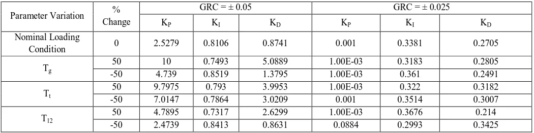
4) Case (iv): Sensitivity analysisSensitivity analysis is carried out to study the power system due to large changes in the system parameters. Taking one at a time, the parameter variation and time constants of speed governor, turbine, tie-line power is altered from their nominal values in the value of +50% to -50% . Table 3 gives the tuned PID controller parameters under parameter variations of GRC is ± 0.05 and
±0.025. The Sensitivity analysis of parameter variations for Tg, Tt, T12 at different GRC of ± 0.05 and ±0.025 shows in table 4 and 5
respectively. It is obvious from Tables 4 and 5 that the dynamic performance with proposed Jaya algorithm tuned PID controller is superior to BFOA optimized PID controller for every cases. Fig. 12 to 17 show various responses at parameter variations of Tg, Tt,
T12 increase 50%, with GRC=±0.05 and ±0.025. Hence, it can be concluded that the proposed control approach provides a strong
[image:8.612.44.569.231.362.2]control under large changes in the system parameter variations.
TABLE : 3
Tuned PID controller parameters under parameter variation.
Parameter Variation %
Change
GRC = ± 0.05 GRC = ± 0.025
KP KI KD KP KI KD
Nominal Loading
Condition 0 2.5279 0.8106 0.8741 0.001 0.3381 0.2705
Tg
50 10 0.7493 5.0889 1.00E-03 0.3183 0.2805
-50 4.739 0.8519 1.3795 1.00E-03 0.361 0.2491
Tt
50 9.7975 0.793 3.9953 1.00E-03 0.322 0.3182
-50 7.0147 0.7864 3.0209 0.001 0.3514 0.3007
T12
50 4.7895 0.7317 2.6299 1.00E-03 0.3676 0.214
-50 2.4739 0.8413 0.8631 0.0884 0.2993 0.3425
TABLE : 5
Sensitivity analysis with GRC = ± 0.025
Parameter Variation % Change
Proposed JAYA Technique BFOA Technique
Settling Time (Sec.)
ITAE Settling Time (Sec.) ITAE
ΔF1 ΔF2 ΔPtie ΔF1 ΔF2 ΔPtie
Nominal Loading
Condition 0 5.3 3.7 7.1582 0.462 9 7.9 8.3 1.5078
Tg
50 5.5 4.6 8.1855 0.5002 7.9 7.4 9.2 1.7988
-50 5.2 3.7 6.1648 0.4319 9.4 8.1 8.7 1.3011
Tt
50 5.6 5.6 8.4516 0.5046 9.2 8.4 7.5 1.3957
-50 5.4 3.6 5.7189 0.4272 9.6 8.6 8.3 1.1458
T12
50 4.9 4.7 8.5674 0.456 8 7.6 5.6 1.2758
-50 5.9 5.8 6.9284 0.5074 11.1 8.2 10.2 2.1568
TABLE : 4
Sensitivity analysis with GRC = ± 0.05
Parameter Variation % Change
Proposed JAYA Technique BFOA Technique
Settling Time (Sec.)
ITAE Settling Time (Sec.) ITAE
ΔF1 ΔF2 ΔPtie ΔF1 ΔF2 ΔPtie
Nominal Loading
Condition 0 2.7 2.8 3.2984 0.10617 4.7 6.4 5.1 0.4788
Tg
50 2.7 3.5 3.703 0.1155 4.8 6.8 5.5 0.476
-50 2.2 2.0 2.7605 0.1021 5.2 6.5 5.4 0.4843
Tt
50 2.6 3.1 3.3579 0.1079 5 7 5.6 0.4634
-50 2.1 3.2 3.2397 0.1073 5.2 6.2 5.1 0.4911
T12
50 3.3 2.9 3.9567 0.1119 5.4 6.3 5.4 0.4771
©IJRASET: All Rights are Reserved
391
Fig.12 Frequency deviation of area-1 due to increase for T12 by 50%, with GRC=±0.05
Fig.13 Frequency deviation of area-2 due to increase for Tg by 50%, with GRC=±0.05
Fig.14 Tie line power deviation due to increase for Tt by 50% ,with GRC=±0.05
©IJRASET: All Rights are Reserved
392
Fig.16 Frequency deviation of area-2 due to increase for Tg by 50% ,with GRC=±0.025
Fig.17 Tie line power deviation due to increase for Tt by 50%, with GRC=±0.02
V. CONCLUSIONS
In this paper, Jaya Algorithm (JA) is applied to optimize PID controller parameters for two area non-reheat thermal power systems with non linearity. It optimized the parameters of PID controller employing an ITAE objective function. The proposed JA based PID controllers provided better performance compared to some already applied techniques such as Ziegler Nichols, Genetic Algorithm and Bacterial Foraging Optimization Algorithms for the equal interconnected power system. Furthermore, the sensitivity analysis is performed by varying the system parameters from their nominal values. It is observed that the proposed controller is robust for wide range of system parameters variations from their nominal values.
REFERENCES
[1] Rabindra Kumar Sahu, Sidhartha Panda, and Saroj Padhan, A hybrid firefly algorithm and pattern search technique for automatic generation control of multi
area power systems Electrical Power and Energy Systems 2015;64: 9–23.
[2] Neha Modi, Manju Khare and Kanchan Chaturvedi.Performance analysis of load frequency control in single area power system using GA and PSO based PID
controller. International Journal of Electrical, Electronics 2013;2 :108-114.
[3] Kundur P. Power system stability and control. Tata McGraw Hill; 2009 [8th reprint].
[4] Rabindra Kumar Sahu, Sidhartha Panda, and Pratap Chandra Padhan , Design and analysis of hybrid firefly algorithm-pattern search based fuzzy PID controller
for LFC of multi area power systems, Electrical Power and Energy Systems 2015;69: 200–212.
[5] Nanda J, Mangla A, Suri S. Some findings on automatic generation control of an interconnected hydrothermal system with conventional controllers. IEEE
Trans Energy Conv 2006;21:187–93.
[6] Parmar KPS, Majhi S, Kothari DP. Load frequency control of a realistic power system with multi-source power generation. Int J Elect Power Energy Syst
2012;42:426–33.
[7] Ghoshal SP. Application of GA/GA–SA based fuzzy automatic generation control of a multi area thermal generating system. Electr Power Syst Res
2004;70:115–27.
[8] Gozde H, Taplamacioglu MC. Automatic generation control application with craziness based particle swarm optimization in a thermal power system. Int J Elect
Power Energy Syst 2011;33:8–16.
[9] Sahu RK, Panda S, Rout UK. DE optimized parallel 2-DOF PID controller for load frequency control of power system with governor dead-band nonlinearity.
Int J Elect Power Energy Syst 2013;49:19–33.
[10] Chandrakala KRMV, Balamurugan S, Sankaranarayanan K. Variable structure fuzzy gain scheduling based load frequency controller for multi source multi
area hydro thermal system. Int J Elect Power Energy Syst 2013;53:375–81.
[11] Saikia LC, Mishra S, Sinha N, Nanda J. Automatic generation control of a multi area hydrothermal system using reinforced learning neural network Controller.
©IJRASET: All Rights are Reserved
393
[12] Saikia LC, Nanda J, Mishra S. Performance comparison of several classical controllers in AGC for multi-area interconnected thermal system. Int J Electr Power
Energy Syst 2011;33:394–401.
[13] Nanda J, Mishra S, Saikia LC. Maiden application of bacterial foraging based optimization technique in multiarea automatic generation control. IEEE Trans
Power Syst 2009;24:602–9.
[14] Ali ES, Abd-Elazim SM. Bacteria foraging optimization algorithm based load frequency controller for interconnected power system. Int J Electr Power Energy
Syst 2011;33:633–8.
[15] Youssef L. Abdel and Magid M.A. Abido.AGC tuning of interconnected reheat thermal systems with particle swarm optimization.IEEE ICECS-2003.
[16] K.S.S. Ramakrishna and T.S. Bhatti .Load frequency control of interconnected hydro-thermal power systems. International Conference on Energy and
Environment, 2006.
[17] R.N. Patel, S.K. Sinha and R. Prasad.Design of a robust controller for AGC with combined intelligence techniques. International Science Index World
Academy of Science,Engineering and Technology 2008;2: 607-613.
[18] B. Venkata Prasanth and Dr. S.V. Jayaram Kumar.Load frequency control for a two area interconnected power system using robust genetic algorithm
controller.Journal of Theoretical and Applied Information Technology 2008; 3:1204-1212
[19] Dr. K. Rama Sudha, V.S.Vakula and R. Vijaya Shanthi.PSO based design of robust controller for two area load frequency control with
nonlinearities.International Journal of Engineering Science and Technology 2010; 2:1311-1324.
[20] Seyed Abbas Taher, Masoud Hajiakbari Fini and Saber Falahati Aliabadi.Fractional order PID controller design for LFC in electric power systems using
imperialist competitive algorithm. Ain Shams Engineering Journal 2014;5: 121-135.
[21] Azadani, H.N.Design of GA optimized fuzzy logic-based PID controller for the two area non-reheat thermal power system. IEEE Fuzzy Systems (IFSC), 13th
Iranian Conference on 2013; 1-6.
[22] Yogendra Arya and Narendra Kumar.Fuzzy Gain Scheduling Controllers for Automatic Generation Control of Two-area Interconnected Electrical Power
System. Electric Power Components and System 2016;1-15.
[23] R.Venkata Rao, Jaya: A simple and new optimization algorithm for solving constrained and unconstrained optimization problems, International Journal of
Industrial Engineering Computations 2016; 7:19–34.
[24] E.S.AliS.M.Abd-Elazim, BFOA based design of PID controller for two area Load Frequency Control with nonlinearities Electrical Power and Energy Systems
2013;51: 224–231.
[25] Sugandh P. Singh, Tapan Prakash, V.P. Singh, and M. Ganesh Babu, Analytic hierarchy process based automatic generation control of multi-area
interconnected power system using Jaya algorithm Engineering Applications of Artificial Intelligence 2017;60: 35–44.
[26] E.S.AliS.M.Abd-Elazim, BFOA based design of PID controller for two area Load Frequency Control with nonlinearities Electrical Power and Energy Systems