l1~alQ3~[1[1
D i l l
D
ITY
FLOPPY DISK
·.INTERFACE
owner's manual
.
TARBELL DOUBLE DENSITY NEWSLETTER July 23, 1981
DFORMAT problem (7-23-80 version):
The inter-record gaps are a little bit long, so if the drive is running fast when formatting, the last byte on the track may run into the first. Symptom snows under DTEST, as track 0 OK, track 1 sector 51 bad, tract 2
and all further tracks with sector 48 (last phsical track) bad. This
may easily be corrected by a one-byte mod to the DFORMAT program. In
the assembly-language, at PUTZERO:, should be MVI B,9 instead ot B,lO. The problem will not be evident if your drive is running correct or slow.
DEBLOCK BIOS AVAILABLE
This bios is set up to work with a mix of disks, single or double density,
l28-byte or 512-byte sectors, single or double-sided. The 512-byte sectors
provide more space on the disk: 600 kilobytes per side instead ot 500. In
most applications, the system will run a little faster. There are two main
disadvantages: 1) the blocking/deblocking routines and buffers take up
space in the bios, so you have lk less of memory available; 2) For systems
doing a lot of random-access writing, the sector must be read into memory, then modified with the l28-byte CP/M sector, then written back out to disk. This requires 2 revolutions of the disk for one sector write, whereas wlth the normal bios, several random sectors could be written in one revolution.
This situation is true for any CP/M system that uses sectors larger than 128 bytes, and could slow the system considerably if many random writes are
being done. For random reads, it should be about the same speed. If you
want this system, order the DEBLOCK BIOS for $25. The disk includes new
routines to format, test, and sysgen,. in addition to the BIOS and BOOT.
PUBLIC DOMAIN DISK #2
This always contains the latest standard support software for the
double-density interface. It includes the bios, boot, format, and test programs,
and costs $15. The current date on this disk is 6-30-81.
FORMAT problem.
Symptom is a message: " ••• Check for write protected disk." Correct by changing line after DONE: in assembly language source from ANI OFFH to ANI OCIH.
CROMEMCO ZPU rev e & f users:
Symptom: difficulty in booting. Correct by removing leg or U47 pin 12
on our board, and reducing or removing C17.
If you are:having any problems, be sure to let us know. Happy customers
sell more interfaces!
NEW PRODUCTS
We have been delivering CPU/IO boards since December, 1980, and people
seem very happy with them. See the enclosed data sheet for more info.
Our EMPIRE series computers, based on this CPU, also is selling well.
Our next board will be a 4-serial/2-parallel I/O port board. We expect
to start shipping this fall, as it is now in the layout stage. We are
still in the process ot evaluating different hard disk systems. Any iaeas
or suggestions· would be appreciated. We are now selling the complete
TARBELL DOUBLE DENSITY FLOPPY DISK INTERFACE TECHNICAL BULLETIN
August 11, 1980
We have found the source of a problem which has haunted some of our
double density customers from time to time. The symptom is that while
doing large transfers, such as a PIP *.* with verify, the routine would
report a verify error, yet there was no error reported from the BIOS.
Other times, the system would just lock up, with no message at all. If
IOU don't have one of these symptoms, you probably don't have this problem,
so you may choose to ignore this part of the bulletin.
We determined that the fault was with the way that the 8257 DMA IC
samples the HLDA (hold acknowledge) line. Since the clock for the
8257 is generated on-board, and is asynchronous with the 8080 or Z80
system clock, the HLDA line may be sampled during it's transition. If
this happens, one circuit in the 8257 may think that the HLDA line is
true, while another circuit in it may think that it's false. This can
cause the 8257 to go into an undefined state.
Since the problem is caused by sampling during a transition, there
are several factors which determine whether and how often it will show. One is the rise-time of the PHLDA signal on the bus, the longer the
worse. This may be affected by position of the interface on the bus
relative to the CPU (the closer the better) r and whether or not the
bus is terminated (unterminated busses usually have faster rise-times).
Another factor is the manufacturer of the 8257. Tarbell has used 8257's
from three manuafacturers: AHD's always have the problem, NEC's have
t sometimes, and Intel's have it the least~
This fix works by using a clock signal from the bus which is syncronous with the PHLDA line to run the 8257 instead of the on-board clock.
1.
2 •
Determine if you have a 2 Mhz clock signal on pin 49 of the S-IOO
bus. This is the frequency that is specified by the IEEE standard,
but older CPU's, especially some Z-80ones, may have some other
frequency, such as 4 Mhz, on this line. This may be determined by
consulting the manual or the manufacturer of your CPU board, or by
measuring it with an oscilloscope or frequency counter. It is also
very important that the line chosen be syncronous with the CPU, that is, derived from the same clock that is used by the CPU IC. This is NOT a requirement of the IEEE standard, so some CPU boards,
especially those using the 8085, 8088, or 8086 processors may not
have asyncronized 2 Mhz signal available. Pin 24 may also be a
good source for 2 Hhz. The IEEE standard DOES specify this line
to be syncronized with the CPU, but does NOT specify that it is
to be 2 Mhz. If you can't find a syncronized 2 Mhz line, call us.
After you have found a 2 Mhz syncronized clock on the S-IOO bus, cut the line from pin 11 of U86 (7493) on the solder side of the board
as shown. Then conRect a jumper from the hole
to the selec~ed S-IOO 2 Mhz pin.
(over)
/I'
II"'t.
TARBELL DOUBLE DENSITY FLOPPY DISK INTERFACE TECHNICAL BULLETIN (cont'd)
To all revision D board owners:
You may have a cut missing from the modifications that brought your
board up to revision E. Check to the right of U41. There should be
a cut on each of three traces there. If there are only two, cut the
trace between those two that are cut.
A note about the MWRITE line:
The MWRITE option available on our board is only for those computers where the MWRITE is not generated directly from the bus signals PWR
and SOUT (as the S-IOO standard specifies). It is not intended as a
substitute for the normal MWRITE line, which must be implemented somewhere on the bus (usually on the CPU or front panel).
A note on dynamic memory boards:
Since we started business in 1976, we have been warning people to avoid
using dynamic memory boards, and to use static boards instead. Although
the new dynamic IC's seem to be more reliable, they still have a higher
susceptibility to alpha particles, causing more soft errors. They are
almost always cheaper and operate cooler. However, they are harder to
troubleshoot, and have a MUCH higher probability of not being compatible with other boards, such as floppy disk inter.faces.
To memory-bank switching customers using extended address lines:
If you are using the extended address register on our interface, it is important to initialize this register before any DMA transfers take place, preferably at the beginning of our coldstart loader (DBOOT).
An example: XRA A OUT FD which would set it to zero.
To our double-sided customers:
We now have support for double-sided drives in the BIOS's for both
CP/M 1.4 and 2.2, and in our DFORMAT program. We have also recently
been testing the double-density interface with the Per Sci 299B double
density double-sided dual floppy disk drive. It has been working very
well! Much better than the earlier models. If you are interested in
the set-up for any of the PerSci drives, call or write us.
Notes on using different sector lengths:
Several customers have asked about using different sector lengths with their Tarbell interface. Although we do not yet have support for this
in our standard BIOS, some of our customers have worked it out. We can
offer one in particular, which uses 512 byte sectors, as is, for a ten dollar copying/handling/diskette charge. '. "As is" means minimally
supported, since we don't "have much experience with it yet. Also note
that this version w'as written for the Z80, £10 customers with 8080 CPU's
will not be able to use it. Using the larger sector lengths give two
advantages: more disk storage, and faster operation. There are also
two disadvantages: uses more main memory (for the buffer and blocking/
Persci 299 Jumpers 8-13-80
The Double density interfac~ has provlslons on the 50 pin drive
connector at the top to allow the connector to modified for small differances between drive manufactures. In particular, Persci drives.
,You will notice that each connection has a double feed through hole with a short etch line connecting each end. By cutting this line with a sharp
ex-acto blade, the line may may be be broken open. To 'allow the persci 299 to work with our interface, some of these lines must be cut, and jumpers put on for the differences between Shugart and Persci. Below is a list of cuts and jumpers to make to this connector.
CUTS
(revision C to revision F only)
Back side of board, cut trace connecting pir, 2 and pin 16 of 50 pin connector. Front side of board, cut the following linefi between feed-through holes:
I
o
holeI
X cut
I
o
holeI
~ut 2,4,6,8,12,14,16,18,24,30,32 as shown above.
Jumpers are referenced as being placed in a FROM - TO fashion as shown below.
[--- Connector---]
2 4 6
I I I
0 0 0
I I I
X X X
I I I
0 0 0
I I I'
Jumpers to inStall: ---~---~
FROM TO
---14 32 18 30
2
4
}~
etc.
TO
cut
Engineering Change Notice for Double Density Interface
Date 8-8-80
This interface requires that you h~ve a 2 MHz clock on pin 49 of
the S-IOO bus in order for it to work correctly. If you have 4 MHz on this
'pin, you will have to divide it by 2 in order to comply with the IEEE spec
which says it must be a 2 MHz clock on this line. Our interface uses this
line (49) to correct a problem we have found which occurs during a DNA cycle.
If you have any problems, please feel free to call us.
G.W.Mulchin
~~~~
Tarbell Double Density Floppy Disk Interface
COPYRIGHT (C) 1979,1980 TARBELL ELECTRONICS ALL RIGHTS RESERVED.
[) P -AS!Y1 l4::V. F
firJ IB~
~ 10/11/&
NO PART OF THIS PUBLICATION MAY BE REPRODUCED, TRANSMITTED, TRANSCRIBED, STORED IN A RETRIEVAL SYSTEM, OR TRANSLATED INTO ANY LANGUAGE OR COMPUTER LANGUAGE, IN ANY FORM OR BY ANY MEANS,
Tarbell Double Density Floppy Disk Interface Revision E
TABLE OF CONTENTS
Page
1 •..••••••••••••.••••••••••
2
3
4
· .
·
. . .
. . .
. .
.
.
. . .
.
. . .
.
.
.
.
.
. .
. .
.
. . .
.
. . .
.
. . .
.
.
• e . • • • • • • • • • • • • • • • • • • • • • • • •
5 •••••••••••••••••••••••••• 6
·
. . . .
.
.
. . . .
.
.
.
.
. . .
.
.
.
. .
7 •••••••••••••••••••••••••• 8 •••••••••••••••••••••••••• 9 ••••••••••••••••••••••••••
10 ••..••••••••••••••••••••• 11
12
.
.
.
. .
.
.
.
.
.
.
.
. .
.
.
.
.
.
.
.
.
. . .
. . . .
.
.
. .
.
.
.
. .
. . .
.
. .
.
.
.
.
.
.
13 ••.•.••••••••••••••.•••••
14 ...••.•....••••...•••• A •••• ,.'~ • • • • • • • • • • • • • • • • • • • •
May 8,1980
Description
Introduction
Software Integration
General Theory of Operation Detail Theory of Operation Reset Circuit
Bootstrap Circuit and listing Address Selection Circuit Disk Control Circuit
Direct Memory Access operation Write Precompensation circuit Data Recovery circuit
Assembly Instructions Jumper Options
Normal Board Setup Address Selection
XRDY or PRDY selection
Write Precompensation Selection Bootstrap jumper
Persci drives
Phase Locked Loop jumpers Interrupt option
Mwrite option 8257 Clock option
1793 Read Delay option Extra buffer chip
Parts List Warranty
Board Layout Silkscreen
IEEE S-IOO BUS Specification S-IOO Compatible Products Disk Test routines
Port and bit definit~ons
Trouble shooting suggestions Disk drive configurations
INTRODUCTION TO THE TARBELL DOUBLE DENSITY FLOPPY DISK INTERFACE
The Tarbell Double Density Interface is an IBM soft sector floppy disk interface using the Western Digital 1791/1793 Floppy DisK controller chip and built to the IEEE S-IOO Stanaard.
This interface is very similar to the now popular Tarbell Single Density Interface in functio~, but with many added new features.
These features include operation as either single or double density, or both, direct memory access (DMA), and extended memory addressing capability, with processor speeds of either 2 or 4 Mhz. The on-board BOOTSTRAP feature allows full system memory of 64K by using the PHANTHOM line on the bus.
Software available to run the double density controller is the widely used CP/M(R) disk operating system, and the new MP/M multi-tasking operating system. Both operating systems use an enhanced I/O system utilizing the new direct memory access capability, and automatic density select features that this product offers.
The capacity of the Disk Operating System running under CP/M in Double Density will be 476 Kbytes for an empty disK, or 243 Kbytes Single Density for an empty disk. The break down is as follows:
Double Density:
The disk will appear to CP/M as 77 tracks of 51 sectors, each sector containing 128 bytes. Because the first two tracks are used by CP/M for the operating system, there will only be 75 tracks available for Directory and data storage. This total space then equals approx. 476 Kbytes.
Single Density:
While running Single Density, the disk will appear to CP/M as 77 tracks of 26 sectors, each containing 128 bytes. The first two tracks are used for the CP/M operating system, leaving 75 tracks available for Directory and data storage, about 243 Kbytes of disk space.
It should be noted ,that the capacities listed above are realized as a result of using the CP/M operating system. If this operating system were not used, then the disk could hold more data, because the disk may be formatted with sectors of 256,512,1024 bytes in length.
For furthe~ information about this, conSlllt the 1791/1793 data sheet
for seccor lengths that may be used.
Note: CP/M and MP/M are trademark and tradenames of Digital Reaserch Post Office Box 579, Pacific Grove, California 93~50.
SECTION 2: GETTING CP/M RUNNING WITH THE INTERFACE
One of the major problems confronting the implementers of new
micro-computer systems, has been the lack of input/output (I/O)
standards. The emergence of Digital Research's CP/M(r) disk
operating system as a standard I/O environment has contributed greatly
to aleviating this problem. Now the problem is reduced to
implementing CP/M on the target hardware system, which consists of
tailoring the BIOS part of CP/M to the situation. Unfortunately,
since we can't assume any particular console interface at the factory, there is no way to make the system generation completely automatic.
Because of all the different ~ossible system configurations, and
because we try to update our hardware and software as quickly as
possible, it has been difficult to create and maintain a set of
documentation that is useful and correct for getting our
double-density floppy disk interface working under CP/M. These
instructions represent a major rewrite effort in this direct10n. We
hope that most of the faults in the earlier instructions have been
corrected in this set.
These instructions explain how to get the Tarbell Double Density
Floppy Disk Interface gOing with Digital Research's CP/M 1.4 or 2.x
disk operating system. It is important not to try and make more than
one change in your system at a time. For example, if you wish to go
from our single density interface operating under CP/M 1.4, to our
double density interface operating DMA under CP/M 2.2 with a different
memory size, DON'T try to do i t all at cnce. First the single-density
to double density, then to DMA, then to 2.2, then to different memory size.
Be sure that the title of the instructions you are going to use,
matches the situation you have. If it doesn't, and you can't seem to
find one that does match, call or write to us, and we'll try to help.
If you don't t~ink you are capable of carrying out the required
instructions yourself, we can generate a customized system for you.
Just have us send you an I/O tailoring questionaire. The cost is
usually about $50.
INSTALLATION NOTES
1. If you have a revision D board (revision letter is at bottom
of board), and the board has been modified according to earlier
addendum
a;
make a cut on the trace to the right of U41, which is thesecond trace down. The traces above and below this trace should
already be cut.
2. The Mt'lRITE option available on our board is only for those
computers where the MWRITE is not generated directly from the bus
signals PWR and SOUTo It is not intended as a substitute for the
normal mJRITE line, which must be implemented somewhere on the bus
(usually on the CPU or· front panel).
3. Install the double density board as close to the CPU as
SECTION 2-1 May 2, 1980
INSTRUCTIONS FOR GETTING THE TARBELL DOUBLE DENSITY INTERFACE OPERATING WITH CP/f1 1.4 v'JHEN YOU HAVE CP/M 1.4 ALREADY GOING ON A TARBELL SINGLE-DENSITY INTERFACE
1. First make sure that your situation matches the title above.
If it doesn't, find another sheet that does match.
2. Check the option jumpers on your double-density interface
board against the manual to make sure the board is addressed for EO
through Fa (hex), and that all other options are correct.
Use your current single-density interface, operating under CP/M 1.4 to do the following steps:
3. Use the FORMAT9l program on the public domain #2 disk
(provided with the interface) to format at least two disks. DON'T use
any of your old format programs to do this. When it says "READY TO
FORMAT?" be SURE to get the public domain disk out of there before
typing Y. Test the disks using the DISKTEST program.
4. Put one of the newly formatted disks in drive B. Put a disk
with your normal CP/M 1.4 system and system programs in drive A. Now
perform the following steps:
a) logged into drive A, type SYSGEN. Answer source as
drive A, destination as drive B. Reboot.
b) type PIP with no arguments, then the following steps.
*B:=A:DDT.COH *B:=A:ASM.COM *B:=A:SYSGEN.COH
c) while still in PIP program, remove your system diskette
from drive A, and insert into drive A the Public Domain #2
diskette that came with the double-density interface. Then
continue as shown below: *B:=A:ABIOS24.ASM
*B:=A:DBOOT24.ASM
5. Now take out the public domain disk #2 and put it aside.
Take the newly formatted disk out of drive B and put it into drive A.
Boot up on~t. It should come up normally, since a copy of your
system wasF just put onto it.
6. Using ED.COM, edit the ABIOS24.ASM to change the EQU's for
your memory size, console, printer, dr:.ves, etc. Leave the DMACNTL
and DUBSID EQU' s set to FALSE. Set the l-1.:>IZE EQU to the same size as
the CP/M 1.4 system you are now running ()n this disk. Be sure to set
the console port numbers correctly. Exit from the editor. Rename the
file to ABIOSxx.ASM, where xx is your MSI~E.
8. Assembl'e ABIOSxx with ASM.COM.
desired, then erase it. Print the .PRN file if
9. Using ED.COM, edit DBOOT24.ASM. set the MSIZE EQU to the
SECTION 2-1 May 2, 1980
size used above. Leave the DOUBSID, DOUBDEN, and DMACNTL EQU's set to
FALSE. Exit from the editor. Rename the file to DBOOTxx.ASM.
10. Assemble DBOOTxx.ASM with ASM.COM. Print the .PRN file if
desired, then erase it.
11. Use SYSGEN to put a copy of your
onto the disk as a file. When it asks for
asks for destination, press carriage-return 32 CPMxx.COM, where xx is your system size.
12. Use DDT to bring in the CPMxx.COM
BIOS and BOOT hex files onto it. Type
current CP/M 1.4 system
source, answer A. When it
to reboot. Then do a SAVE
file and to overlay the
DDT CPMxx.COM • Then type
IABIOSxx.HEX
.
Then type Rbias where bias is in the table below:xx bias xx bias xx bias xx bias
20 D480 24 C480 28 B480 32 A480
36 9480 40 8480 4,4 7480 48 6480
52 5480 56 4480 60 3480 64 2480
Now type IDBOOTxx.HEX • Then type R900 • Then do Ctl-C.
13. Next enter SYSGEN. When it asks for source, press return to
skip. When i t asks for destination, type A. At this point you may
write this system onto more than one disk. After you are finished
writing onto the disk(s), DON'T press return to reboot.
14. You can now shut off your computer, remove the single
density interface, and put the double-density interface in. Then turn
your computer back on.
15. The system you have just written onto one or more disks
should now boot up correctly on the double-density interface. If it
doesn't, check over the BIOS and BOOT .PRN files to make sure all
EQU's were set correctly. Check your board to verify again that all
the jumper options are right. If you st~ll canlt get i t going, read
section 2-3 of these instructions.
16. If the system does come up cor:ectly, congratulations! You
are now running the double-density interface in non-DMA mode. If you
want to ;operate double-density next, see section 2-2 of these
instructions. If you want to try operating in DMA mode, go to step 6
in this section, changing the DMACNTL EQU to TRUE in both the BIOS and
the BOOT .ASM files. The rest of the instructions are the same.
17. Finally, if you notice any errors in this documentation,
SECTION 2-2 l\pril 24, 1980
HOW TO MAKE THE TARBELL DOUBLE DENSITY INTERFACE OPERATE IN THE DOUBLE DENSITY MODE ASSUMING YOU HAVE THE DOUBLE DENSITY INTERFACE OPERATING IN THE SINGLE DENSITY MODE.
1. Check your situation against the title above. If it doesn't
match, look for other instructions that do. In order to operate in
double density mode, you will either need to be operating at 4 or
above 4 Mhz (Z80 or 8085), or you need to be operating in DMA mOde.
To set DMA mode, see step 16 of the instructions in section 2-1.
2. Format some disks double density with DFORMAT, and test them
using DTEST.
3. If you boot up on a single density system which was created
using the auto-select I/O section (ABIOS or 2ABIOS), all you have to
do is put the formatted double-density diskette in drive B. Files may
be transferred to the new double density disk using PIP. Don't try to
use the COpy utility to copy from single density to double density or
vise-versa.
4. If you want to put a system from the first two tracks on the
single density disk onto a double density disk, SYSGEN alone will not
work. This is because the first sector of the first track contains a
byte which has to be DD (hex) for double density, and your
single-density disk doesn't have that byte. To perform this operation
correctly, follow these steps:
a) On your single density disk, edit the file called DBOOTxx.ASM
to change the DOUBDEN EQU from FALSE to TRUE. It is important that the MSIZE match your current CP/M system size (xx)_
b) Assemble the new file: ASM DBOOTxx
c) Do a SYSGEN, answering source on A, skip the destination and
reboot. Enter SAVE 34 CPMxx.COM where xx is system size.
d) Then overlay the CPMxx.COM system image with the new DBOOT:
DDT CPMxx.COM IOBOOTxx. HEX R900
e) Then press contro1-C to return to CP/M.
f) Then do another SYSGEN, this time skipping the source, and
answering B to the destination. (This assumes you still have
y.our double-density disk in B.)
5. Now you can take the double density disk out of drive Band
SECTION 2-3 May 2, 1980
WHAT TO DO IF YOUR TARBELL DOUBLE DENSITY FLOPPY INTERFACE IS NOT WORKING
1. Recheck the jumper options on the interface board against
your manual in section 6. Note that manuals of boards rev Band
earlier have an error in the board addressing section. People with
these manuals can get a new manual free by sending us the cover of
their old manual.
2. Recheck the EQU's in the BIOS and BOOT .ASM files to make
sure that all are set correctly.
3. If you have a friend with a working Tarbell Double
Interface, try using your interface in his computer. If his works and
yours doesn't, there is probably something actually wrong with your
interface. If so, you might want to consider sending it back to
Tarbell for repair. If your interface does work in your friend's
computer, the problem might be in your software, or in some other
component of your system. Just because the other components of your
system work under other circumstances, doesn't mean that there is
nothing wrong with them.
4. Another thing to check is the diskette that you're using.
Is it formatted correctly? How do you know it is?
5. Do you have dynamic memory in your computer. If so, how is
it refreshed? It is possible that the way it is refreshed interferes
with our interface, or that the way our interface works interferes
with the memory's refresh circuitry.
6. Does your CPU board fully implement the new IEEE S-lOO
standard? In particular, does it use pin 67 (the phantom line) for
anything besides phantom? Does it implement the control-disable,
data-disable, and status-disable lines? Does it implement the PSYNC,
PHOLD, and PHLDA lines? Neither the SDS SBC-IOO or SBC-200 CPU boards meet this requirement.
7. Does the memory which occupies address 0000 in your system
have a phantom line on pin 67?
8. -Do you have other boards in your system that use the XRDY
and PRDY lines (pins 3 and 72) besides the Tarbell interface and the
CPU? If so, it might be best to disconnect those lines completely.
9. Since the Tarbell Double Density Floppy Disk Interface uses
lines on your motherboard that aren't normally used, some of these
lines could be shorted or open, or the connector pins could be dirty.
10. Check your system power supply, with a scope if possible, to
make sure that all your vol tages are st,~ady, clean, and the right
level, both on the drives and the moth~rboard. It is very important
that on the drive power supply, the 24 'Jolt, 5 volt, and -5 volt
returns be connected together at the power supply end.
SECTION 2-3 r·~ay 2, 1980
11. If you 'are having problems with the bootstrap, it's possible
that C17 is not a high enough value to reduce the effects of ringing
on the bus. You might try 220, 390, 470, or 680 pf capacitors, in
that order. The symptom is that the bootstrap flip-flop gets reset
before it has a chance to read a complete sector. This can be seen by
looking at pin 19 on the 8257. This DRQ line should be a series of
short pulses that should happen over a period of about 2 ms. If they
don't last that long, you may have this problem.
12. If the DRO line mentioned above never goes high at all, that
means the interface is never receiving a valid data byte. This could
be caused by a variety of factors, including a bad data separator
component, bad 1793, bad drive, etc.
13. If the interface' is picking up excessive errors after
warming up, it could be the 1793. We are now testing these IC's more
carefully.
***
NOTE***
If you decide to send the interface back for repair, be sure to
include a copy of your receipt, showing the date you bought it. Note
SECTION 2-4 Hay 2, 1980
INSTRUCTIONS FOR GET'l'H1G THE TARBELL DOUBLE DENSITY
INTERFACE OPERATING WITH CP/H 2.x WHEN YOU HAVE CP/M
2. x ALREADY GOING Otl A Tl\HBELL SINGLE-DENSI'rY INTERFACE
1. First make sure that your situation matches the title above.
If it doesn't, find another sheet that does match.
2. Check the option jumpers on your double-density interface
board against the manual to make sure the board is addressed for EO
through F8 (hex), and that all other options are correct.
Use your current single density interfaCE!, operating under CP/M 2.x to do the following steps:
3. Use the FORHAT9l program on the public domain #2 disk
(provided with the interface) to format dt least two disks. DON'T use
any of your old format programs to do this. When it says "READY TO
FORBAT?tI be SURE to get the public domain disk out of there before
typing Y. Test the disks using the DISKTEST program.
4. Put one of the newly formatted disks in drive B. Put a disk
with your normal CP/N. 2.x system and system programs in drive A. Now
perform the following steps:
a) logged into drive A, type SYSGEN. Answer source as
drive A, destination as drive B. Reboot.
b) type PIP with no arguments, then the following steps.
*B:=A:CPH.COH
*B: =A: DDT. cor·1
*B:=A:ASt1.COf1 *B:=A:SYSGEN.COM *B:=A:ED.COH
c) while still in the PIP program, remove your system diskette
from drive A, then insert into drive A the Public Domain #2
diskette that Came with the double-density interface. Then
continue as shown below: *B:=A:2ABIOS24.ASM
*B:=A:2DBOOT24.ASM
5. Now take out the public domain disk 12 and put it aside.
'.l'al~e the 'ne'VJly formatted disk out of dr:.ve B and put it into drive A.
Boot up on it. It should corne up normally, since a copy of your
system was just put onto it.
6. Using ED.Cml, edit the 2ABIOS24.A8[1 to change the EQU's for
your memory size, console, printer, drives, etc. Leave the DMACNTL
and DUBSID EOU's set to FALSE. Set the MSIZE EQU to the same size as
the CP/M 2.x system YQu are now running on this disk. Be sure to set
the console port numbers correctly. If you have Shugart 800 drives,
don't set the s'tep rate any faster than 10 ms. Exi t from the edi tor.
Rename the file to 2ABIOSxx.ASM, where xx is your MSIZE.
8. Assembl e 2ABIOSxx 'Vvi th AS1>1. C0r1.
SEcrION 2-4 I'lay 2, 1980
9. Using ED.'COf>1, edit 2DBOOT'24.ASM. Set the BSIZE EQU to the size used above. Leave the DOUBSID, DOUBDEN, and mlACNTL EQU's set to FALSE. Exit from the editor. Rename the file to 2DBOOTxx.ASM.
10. Assemble 2DBOOTxx.ASM with ASH.COM. Print the .PRN file if desired, then erase it.
11. Use SYSGEN to put a copy of your onto the disk as a file. When it asks for asks for destination, press carriage-return
34 CPMxx.COM, where xx is your system size.
current CP/M 2.x system source, answer A. When it to reboot. Then do a SAVE
12. Use DDT to bring in the CPMxx.COM file and to overlay the BIOS and BOOT hex files onto it. Type DDT CPMxx.COM. Then type 12ABIOSxx.HEX. Then type Rbias where xx is MSIZE and bias is in the table below:
xx bias
20 D580 36 9580 52 5580
xx bias
24 C5S0
40 8580
56 4580
Now type I2DBOOTxx.HEX
xx bias
28 B580 44 7580 60 3580
xx bias
32 A5S0
48 6580 64 2580
Then type R900. Then do Ctl-C.
13. Next enter SYSGEN. When it asks for source, press return to skip. When it asks for destination, type A. At this point you may write this system onto more than one disk. After you are finished writing onto the disk(s), DON'T press return to reboot.
14. You can now shut off your computer, remove the single-density interface, and put the double-density interface in. Then turn your computer back on.
15. The system you have just written onto one or more disks should noVl boot up cor rectly on the doubl(~-densi ty interf ace. If it doesn't, check over the BIOS and BOOT .PRN files to make sure all EOO's were set correctly. Check your board to verify again that all the: jumper options are right. If you still can't get it going, read section 2-3 of these instructions.
16. If the system does come up correctly, congratulations! You are now running the double-density interface in non-DMA mode. If you want to operate double-density next, see section 2-2 of these instructions. If you want to try operating in DNA mode, go to step 6 in this section, changing the DMACNTL EQU to TRUE in both the BIOS and the BOOT .ASM files. The rest of the instructions are the same.
17. Finally, if you notice any errors in this documentation, PLEASE call or write about it.
SECTION 2-5 April 25, 1980
GETrrING THE TARBELL VERSlmJ OF CP/~l 1.4 OR 2.X RUNNING ON
YOUR TARBELL DOUBLE-DENSITY FLOPPY DISK INTERFACE WITHOUT A CURRENTLY RUNNING CP/M SYSTEM OF ANY KIND
1. First make sure that your sitlation matches the title above.
If not, you may find that another set of instructions will get your
system going sooner.
2. You need to have the following hardware installed:
a) An assembled and tested Tarbell Double Density Interface
b) At least 24k bytes of random access memory, of which at
least the first '32 bytes can be disabled by phantom line pin 67 going low.
c) A Z-80, 8085, or 8080 CPU board which conforms to the IEEE
S-lOO standard.
d) A console interface of some type, preferably not
memory-mapped video, which supports an alphanumeric keyboard and
a CRT display or teleprinter. If possible, this interface
should be addressed for status on port 0, data on port 1, with bit 0 of the status low meaning keyboard ready, and with bit 7 of the status low meaning CRT display ready.
If these port and status requirements are met, the Tarbell CP/M 1.4 or 2.x disks for the DD controller should boot up
with no further work. Just put the disk in, push reset,
and run. Skip to step 8 if so. If not, you will need to
fulfill the requirements of substep (e) below and continue.
e) Ei ther a f rant panel or a Rm.', monitor (any ROl,1 should be
outside the 24k RAt1), \'ihich allows depositing bytes into specified RAM addresses and executing at an address.
3. If possible, have a friend make a copy of your original CP/N
disk, and don't use it except to make further copies. Then use the
copy for the following steps.
4. Turn the computer on, then the CRT-keyboard, then the drive
power.
5. Put the CP/M disk into the disk drive (on most drives, the
label on the disk should face the door of the drive). Close the door.
Push rese~ (and run if you have one) buttons on the computer.
6. The head should load against the disk and move in one track.
If it doesn't do this, something is wrong with the hardware setup, and
you should try a few times more. If it still doesn't do it, FIRST
remove the diskette, then shut down the system. Something is either
wrong with the hardware or the diskette. If so, have someone look at
it or call Tarbell. If it does load and step ok, go onto the next
step.
7. Either stop the computer from running, if you have a front
panel, or jump into your ROl\l monitor, if you have one.
8. Look at the BIOS (Basic Input Output System) listing that
SECTION 2-5 April 25, 1980
came with our' CP/M. Find the label BOOT. After the LXI SP
instruction, you will see a series of NaP's. This area is reservea
for initializing console interfaces that require it. Using either
front panel or ROM, deposit the initialization routine required, if
any, at the address indicated by the listing. There should be a copy
of any required initialization routine in the manual on your console
interface. Assembly language code for the initialization of some
common console interfaces can .be seen in the following lines on the
page.
9. Still looking at the BIOS listing, find the label CaNST.
Examine the code there for our "standard" interface. Put the code
here to do a status check on your console interface. Notice that if
your status bits are true when high, instead of low like ours, you
will need to change the RNZ to an RZ. Other changes which might be
required are the port number after the IN, and the mask after the ANI.
Check your console interface manual for examples and instructions.
10. The next routine is labeled CONIN. Deposit the code to read
a byte from your console keyboard into register A. Notice that you
might need to make similar changes, such as JNZ to JZ, mask, and port numbers.
11. The last routine to change is
code to write the byte in register
might need to replace our JNZ with a JZ
changes. Be sure to end each of
instruction.
12. This should be all the patches
labeled CONOT. Deposit the
C to your console. Again, you
ane make port number and mask
these routines with an RET
you need to make to the CP/M
system residing in memory, to get going temporarily. Now examine the
content of address 5AOO (hex), which should be a C3 (hex for JMP) and
execute (run) at that location.
13. Our BIOS should give
on the air, so go to step 14.
properly, and something may be
setup. In that case, refer to
you an opening message. If so, you're
If not, the system may not have loaded wrong with the diskette or hardware
section 2-3.
14. If you 'haven't already done so, copy the system and files
onto anothc;J:.' di sk. In order to do this, keep your system di sk in
drive A and put a blank disk into drive B. Then type: COpy ALL. This
will copy your original disk ont6 the blank disk. Note that the
system you are running is only in memory, and the system on the disk
hasn't yet been modified. Leave the new disk in drive B until you
press return to reboot. Then take the original disk out of drive A
and never use it again except to copy it. Now remove the copy you
made from drive B and label it exactly the same as the original. You
will find that it is impottant to keep the disk labels current, as it
is easy to get rconfused and make a mistake. Put the new copy into
drive A for further work. Then pressCtl-C.
15. 'rhe ne'xt thing to do is edit the BIOS and BOOT .ASM files
and overlay them onto your system. Use the method described in the
SECTION 2-5 April 25, 1980
Tarbell CP/M 1.4 or 2.x User's Guide, as this will properly document all your changes and allow you to make use of memory larger than 24k.
CONTENTS OF PUBLIC DOMAIN DISK #2 May 2, 1980
This is a disk which is regularly updated with our latest AGIOS
and 2ABIOS for the Tarbell Double Density Floppy Disk Interface.
Other utilities are also maintained on this disk, such as format and
test routines. We also had room to ir.clude the source for the FORTH
language from the Forth Interest Group. Their name and address arc
included on the .ASM file. Following is a short description of each
file. For further information, see the comments in the file itself,
or the Tarbell CP/M User's Guide. The latest version of this disk is
always available within 1 week from Tarbell for $15. If you are
having problems, it's always wise to see if there is a newer version
of this disk available than the one you have.
1. DBOOT24.ASH
TH IS IS THE SAME AS THE NOm-tAL SBOOT PROGRAH USED IN SINGLE
DENSITY, WITH THE EXCEPTION OF A DENSITY CONDITIONAL STATEHENT. AT
THE PRESENT TIME SETTING THIS EQU TO EITHER TRUE OR FALSE WILL MAKE NO
DIFFERENCE TO THE BOOTING OPERATION. THE REASON IT IS THERE IS FOR
DOING AUTO-DENSITY SELECTION DURING BOOTING.
2. DDUMP.ASM & DDUMP.COM
THIS IS A HODIFIED DUMP.COl'-l FROt-l SAr·1 SINGER AND FROI1 THE CP/r·l
USERS GROUP. THIS PROGRAM vlILL ALLm'1 YOU TO VIEW ONLY TRACKS 2 - 76 OF
A DOUBLE DENSITY DISK. THE ONLY LUUTATION IN THE PROGRAH IS THAT IT
WILL NOT DUMP BY GROUP NUMBERS. ALL OTHER FEATURES ARE USEABLE.
3. DFORMAT.ASM & DFORMAT.COM
TH IS PROGRAM IS THE DOUBLE DENSITY FORr1AT PROGRAr·l. IT WILL
FORHAT THE DISK IN ~1ANY WAYS DEPENDING' ON tvHICH EQU'S YOU SET TRUE OR
FALSE.
For example:
SETTING TRKISD
=
TRUE,FORl"lA'l'S TRACK 0 AND 1 SINGLE DENSITY.
TRACK 2 - 76 DOUBLE DENSITY.
OR
SETTING TRKIDD
=
TRUE,FORMATS TRACK 0 IN SINGLE DENSITY.
TRACKS 1 - 76 DOUBLE DENSITY.
***
NOTE***
ONLY ONE (1), TRI<lSD OR TRKIDD MAY BE TRUE AT A TIME. THE SKEvJ
FACTOR IS EASILY CHANGEABI.E IN THE DFORMAT PROGRAM TO ALLOW FOR
OPTIMIZING DISK SPEED.
AS SIDE SEI.ECT IS ONLY SUPPORTED BY CHANGING YOUR DRIVE SELECT
IF YOU HAVE DOUBLE $IDED, FORr1ATTING HIDE B vlITH THE DFORMAT PROGRA~l
HAY OR HAY NOT ~vORK FOR YOU.
4. DTEST.ASM & DTEST.COM
THIS PROGRAI·1 IS USED TO TEST A DOUBLE DENSITY DISK FOR ERRORS.
WHEN THE PROGRAM FIRS'l' COfl1ES UP IT WILL ASK YOU FOR A "TITLE: ". YOU
CONTENTS OF PUBLIC DOMAIN DISK #2 May 2, 1980
MAY TYPE IN ANYTH ING YOU l<'lANT SUCH AS <FORMATTED ~v ITH 62.5 NSEC, 187 .5
NSEC> AND THEN A CNTL-P, CARRIAGE RET, OR IF YOU DON'T WANT TO TYPE
l\NyrrH ING, JUST TYPE A CARRIAGE RE'l'. 'J'HE TITLE ALLOWS YOU TO KEEP A
RUNNING TAB ON THE ERRORS AND USING CNTL-P WILL TURN ON THE LIST
DEVICE FOR MAKING A HARDCOPY LISTING. THE NEXT QUESTION WILL BE
STARTING TRACK. YOU MUST ANSWER THIS WITH A TRACK NUl'iBER OF 0 OR
GREATER. THE REST OF THE PROGRAM SHOULD BE CLEAR. THIS PROGRAM READS
A TRACK AT A TIME AND KEEPS A RUNNING TAB OF ERRORS FOUND. DURING THE
READING OF THE TRACK, IF A SECTOR IS BAD IT WILL DISPLAY THE SECTOR
NUMBER AND THE NUMBER OF RETRYS IT TOOK TO READ IT. IT SHOULD BE NOTED
THAT IT WILL DO 11 RETRYS MAX, AND THEN GO ON TO THE NEXT SECTOR. IF
IT TAKES MORE THAN 10 RETRYS, THEN YOU SHOULD REFORl1AT THE DISK AND
CHECK IT AGAIN, AS OUR nBIOS ONLY DOES 10 RETRYS BEFORE INDICATING A
FAILURE. RETRYS ON THE ORDER OF 1 TO 5 IS TYPICAL, IF THEY OCCUR AT
ALL, lHTH THIS INTERFACE. THIS PROGRAl<l DOES NOT WRITE ON THE DISK, IT
IS READ ONLY.
5. FORMAT. ASf.\ & FORl-1AT. COM
IF YOU ARE USING OUR OLD SINGLE DEKSITY FORMAT PROGRAl-'l, YOU NILL
NOT BE ABLE TO READ THEr.1 ON THE NE~A] INTEF.FACE IN SINGLE DENSITY. TH IS
IS BECAUSE THERE IS A BYTE IN THE INNER PECORD GAPS THAT THE 1771 WILL
READ BUT THE 1791/1793 WON'T. THIS FOR~[AT PROGRAr,1 FIXES THAT PROBLEM
FOR BOTH THE 1791/1793 AND ~VILL STILL ALI.OW YOU TO USE IT ~VITH YOUR
PRESENT 1771 CONTROLLER ALSO. YOU SHOULD DESTROY AND OLD COPIES OF THE 01.0 FORMAT PROGRAM YOU HAVE, AND USE THIS ONE FROM HERE ON OUT.
***
NOTE***
THIS FORMATS SINGLE DENSITY ONLY; 26 SECTORS OF
ONLY RUNS ON THE N~·J CONTROLLER BOARD.
6. FORI1AT91.ASM & FORMAT91.COM
128 BYTES
This program will only run on the single-density interface. It
will format disks in standard IBM single-density format, to read
correct~y on the double density interface.
7. DFRAND.ASI1
This: is another format program, \'lhich only runs on the
double-density interface, and which formats disks double-density in a
random format. This is very useful to use in conjunction with the
DTEST program, while setting up precomp. It gives a more realistic
representation of the way that data may be present on the disk. Do
NOT use this program to format disks that are to be used next with
CP/M, as the directory needs to be fifled with E5's •
.
8. MACRO.LIB & SKEW.LIB
..
THIS LIBRARY IS NECESSARY· IF YOU HAVE DIGITALS 11ACRO ASSEMBLER
AND WISH TO CHANGE AND ASSEMBLE DDUMP.ASM AND DTEST.ASM. THESE
CONTENTS OF PUBLIC DOMAIN DISK #2 May 2, 1980
9. STAT.COM (FOR CPM Vl.4 ONLY)
THIS IS AN UPDATED VERSION OF THE STAT PR(X;Rl\N FOR 'l'HE
DIS'rUHI3U'rION. IT FUNCTIONS THE SAME AS THE OLD ONE.
INPROVEMENT \'1AS TO HAKE IT DISPLAY THE CORRECT CAPACITY OF
DENSITY DISK. IT WILL STILL WORK SINGLE DENSITY.
10. ABIOS24.ASM
ORIGINl\L
THE ONLY
A DOUBLE
THIS IS THE AUTO-DENSITY SELECT VERSION OF THE BIOS FOR CPM
Vl.4. THIS BIOS WILL AUTDr1ATICALLY SELECT THE DENSITY OF THE DISK YOU
ARE USING IN EITHER DRIVE, AND WILL ALLOH YOU TO CHANGE THE DENSITY AT
ANY 'rum. IF YOU ARE GOING TO CHANGE THE DENSITY OF THE "A" DRIVE,
YOU ~1UST HAVE A DISK WITH THE SAME SYSTEl1 SIZE AS THE ONE YOU RE~lOVED.
FILE TRANSFERS FROM SINGLE TO DOUBLE OR DOUBLE TO SINGLE IS COMPLETELY
AUTOMATIC. YOU MUST SET DOUBDEN = TRUE IN THE DBOOT24.ASM FILE BEFORE
YOU USE THE AUTO-DENSITY CAPABILITY OF ABIOS24.ASM, AS THIS IS THE
ONLY liAY THE PROGRAM KNOWS IT IS LOOKING FOR A DOUBLE DENSITY DISK IN
ANY DRIVE.
11. 2ABIOS24.ASM
TH IS IS THE AUTO-DENSITY SELECT VERSION FOR CPI·1 V2. x AND THE NE\'1
INTERFACE. THIS BIOS MUST BE USED WITH 2DBOOT24.ASM TO BRING UP THE
SYSTEf'1. PLEASE NOTE THAT 2ABIOS24 AND 2DBOOT24 ARE ONLY FOR CPM V2.x
AND WILL NOT RUN ON CPM V1.4 OR CONVERSELY. THIS BIOS IS SHIPPED
READY TO RUN IN THE AUTO SELECT MODE. YOU MAY CHANGE THIS AFTER YOU
GET A RUNNING SYSTEM SO THAT IT NILL NOT RUN AUTO SELECT BY SETTING
DOUBDEN
=
FALSE. YOU MAY ALSO DEFEAT THE DMA PORTION BY SETTINGm1ACNTL
=
FALSE, WHICH WILL ALLOvl THE BIOS TO RUN IN PROGRAH DATA'llRANSFER.
*** NOTE ***
YOU MUST SET DMACNTL
=
TRUE AND DOUBDEN=
TRUE IF AUTO DENSITYSELECT IS NEEDED AND YOU WILL BE RUNNING DOUBLE DENSITY at 2 MHz.
12. 2DBOOT24.ASM
THIS IS THE SECONDARY COLD START LOADER FOR CPM V2.x FOR USE
IljJ'rB 2ABIOS24.ASM. SEVERAL EQU'S APPEAR IN THIS LOADER.
DMACNTL-SETTING TH IS TRUE WILL ALLOW THE PROGRAM TO BOOT IN THE SYSTEM. USING
DMA CONTROL. IF FALSE, BOOTS SYSTEr1 UNDER PROGRAt'l DATA TRANSFER.
DOUBDEN - SETTING THIS TRUE PUTS THE SPECIAL ID BYTE INTO THE DISK
DURING GENERATION OF A DOUBLE DENSITY SYSTEM DISK THAT WILL BE BOOTED
IN FROM. DRIVE IA'. SETTING THIS FALSE ALLOWS BUILDING A SYSTEM ON A
SINGLE DENSITY DISK. THIS BYTE IS HO~'J THE SYSTE~1 KNOWS WHETHER OR NOT
A SINGLE OR DOUBLE DENSITY IS ON LINE.
**** NOTE-****
IF YOU HAVE TROUBLE READING A SINGLE DENSITY DISl< ON THIS
CON'rROLLER, YOU MAY HAVE A DISK WITH THE WRONG SECTOR FORMATTING. TO
FIND OUT, TAKE ANOTHER DISK AND USE THE NEW FORMAT. COM FILE ON THIS
DISK TO REFORMAT IT. THEN USING YOUR OLD CONTROLLER, TRANSFER ALL THE
PROGRAMS YOU vHSH TO SAVE FROM THE DISK THAT WOULD NOT RUN ON THE NE\'l
CONTENTS OF PUBLIC DOMAIN DISK' #2 May 2, 1980
CONTROLLER BOARD TO THE NE~'JLY fORiI'lA'l'TED DISK. WE REALIZE THAT TH1S IS
ALSO A REAL HASSEL TOO, BUT IT IS A NECESSARY EVIL. BESIDES, THE N~l
FROHATTED DISK vlILL STILL vJORK WITH THE OLD CONTROLLER BOARD.
***
NOTE***
IF ALL ELSE FAILS, EVEN AFTER READING THE DIRECTIONS, FEEL FREE
TO CALL ME HERE AT TARBELL ELECTRONICS. AND IF YOU WOULD LIKE TO
DISCUSS ANYTHING ABOUT THE BOARD OR SOFTWARE, CALL HE.
THANKS FOR INPUTS AND OUTPUTS ON THIS PRODUCT AND HOPE YOU WILL
FIND TH IS PRODUCT BOTH INFORMATIVE AND FUN TO t"lORK WITH.
GERALD.W.MULCHIN ENGINEERING DEPT. TARBELL ELECTRONICS
GENERAL THEORY of OPERATION
The internal operation of a floppy disk operating system is
probably the most complicated part of a micro-computer system. The
hardware and software interact very closely, and therefore a very
strong knowledge of 8080 assembly language and common logic operations
is desirable to understand this section. Knowledge of the IEEE S-IOO
standard is also desirable, as there are some changes that have been
made to the S-IOO bus with this new specification. The IEEE S-IOO
Standard has been enclosed with this manual in the appendix, along
with the data sheets for the rest of the integrated circuits used on
the interface.
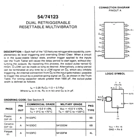
The heart of the Double Density interface is the 1791/1793 Floppy
Disk Controller Chip. This chip is very similar to the 1771 in
operation, but now includes all the functions necessary to run Double
Density. For your convenience, the 1791/1793 data sheet is included
in the appendix.
~he interface may be broken down into subsections as follows:
1. 1791/1793 disk controller chip.
2. 8257 Direct Memory Access Controller chip. 3. Phase Locked Loop circuit.
4. Write Precompensation circuit.
5. General Drive and Computer interface.
The 1791/1793 controls the actual reading or vlriting to the floppy
disk, and in which density this will bappen. The floppy controller
chip contains 4 internal registers which are programmed by the
cORputer through i t ' s data and address lines. the four registers are
as follm'ls:
1. status register 2. track register 3. sector register 4. data register
Review of the data sheet will help in understanding each function of
these 4 registers.
DDEt1 is used to control in which density the floppy disk controller
chip will be operating. Low equals Double Density, High equals Single Density.
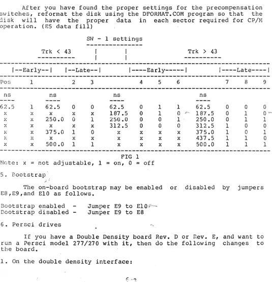
EARLY and LATE control the Write Precompensation of the data being
written to the disk. These two signals along \vith the TRK
>
43 linecontrol the amount of shift in time the bit that is being written to
the disk is subjected. Precompensation during writing is a must
because of the bit packing on the meaium of the disk.
'This interface also hilS provisions for precompensation on tracks
<
43, and i t is recommended that a small amount be used. The amount of
precompensation is a switch selection, and will be explained in the
juroper options.
READ GATE is an output used for synchronization of the data
seperator circuit during read operations. A high on this pin inaicates
GENERAL THEORY of OPERATION
that ,a field of 'ones' (or zeros) has been found in the inner record
gaps of the disk.
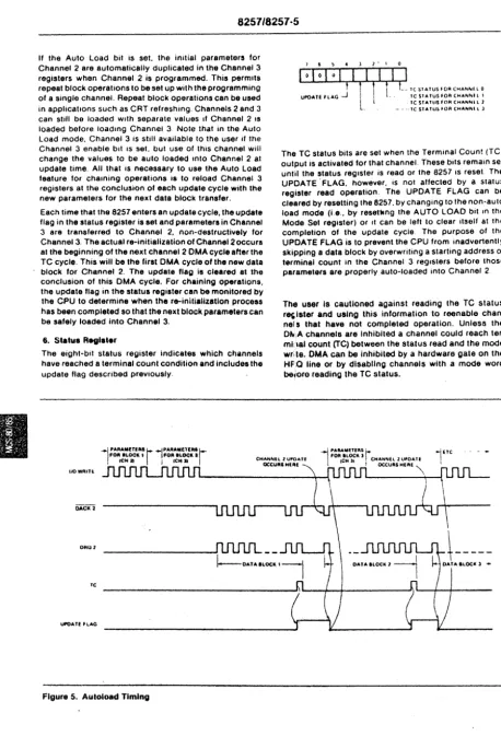
The 8257 Direct Memory Access Controller chip controls the actual transfer of computer data between the disk and computer. This device
can be thought of as a high speed semi-intelligent cpu in its
operation. It contains 16 registers of which only 3 are used by this
floppy disk interface board. One is a command register, and the other
two are byte pair data registers. During read and write operations,
the 8257 must be initialized with the byte transfer count, the address of where the data is to go, and the type of transfer that is to occur,
such as read or write. The 8257 can transfer up to 16384 bytes of
data, and put it into any memory locations within a normal 80~0's
addressing range. The important aspect about the 8257 is that it will
transfer data to or from memory without the need of any cpu
intervention other than being initally programmed by the cpu. After it
has been programmed, it alone transfers the data, and in fact removes
the cpu from the 5-100 bus during these transfers. In-depth
information about the 8257 is available in the INTEL data catalog ana in the appendix of this manual.
The Phase Locked Loop circuitry on this interface is necessary for reliable data recovery, especially while running under double density.
It's function is to remove effects of data fluctuations during READ
operations which may be the result of drive speed or power line
changes, and general system noise. The Phase Locked Loop is used
during 5ingle and Double Density operation. This is accomplisheu by
logic on the interface and is controlled by the DDEN line and an
internal hardware latch. Tri-state switching is used to selecc the
m~ster oscillator timing clock. When in Single Density, the master
clock is equal to 8 Mhz. Double Density selection causes the master
clock to change to 16 Mhz. A close examination of the schematic will
sbo\'/ these logic changes during density selects.
The write precompensation is in general terms really a count down
circuit, controlled by the EARLY, LATE, and TRK
>
43 lines duringwriting operations. This applies only when operating in double
density, as the EARLY and LATE signals are not active during single
density. The count down circuit is clocked by the 16 Mhz master
oscillator circuit. The amount of precompensation is determined by
the preset v;a:lue jammed into the 74LS161 from the EARLY or LATE pins
of the floppy chip. After this value is loaded, the 74L5161 counts
until it reaches zero, at which time it writes the data to the disk.
The effect of this is to delay the time the bit would have been
written to the disk, until it is actually written. The smallest amount
of precompensation that may be realized fro~ this circuit is:
1 / 16 Mhz = 62.5nsec. .
Jumpers provided on the ipterface have been selected for optimum drive
performance. Selection is based on manufacturer's recommendations for
the drive in use, and our testing here at Tarbell Electronics.
The computer interface for this board is based on the IEEE 5-100
bus interface specification. It is not radically different from the
old 5-100 bus design, and should run with most 8-100 products on the
GENERAL THEORY of OPERATION
market. If you have any qucst{ons about your interface cards, chcck
the section on 8-100 compatible products in our manual.
The Disk Interface occupies an address range from EO-EF hex for the
DMA controller portion and FH-FD hex for the disk controller portion.
A jumper is provided to allow the address range to be moved to 60-6F
hex and 78-7D hex respectively, to avoid address conflicts wl~h
exsiting computer boards you may have in your system. This is
explained in the jumper options section. The address ports are used
as fOllows:
EO hex
81 hex
E8 hex
F8 hex
F8 hex
F9 hex
FA hex
FB hex
FC hex
FC hex
FD hex
FD hex
8257 address register (must be two bytes to this port) 8257 word count register (must be two bytes to this port) 8257 command register (1 byte)
disk command port (input) disk status port (output) disk track port (input/output) disk sector port (input/output) disk data port (input/output) wait control port (input) drive select port (output)
DMA end of operation port (input) extended address port (output)
TilC extended address port (FD hex), allows the DMA controller to
transfer data to and from memory beyond the normal 64k range of the
8080 cpu. This function is avalible for both read and write operations
using the disk interface. The extended address lines are provided on
the S-lOO bus as described in the IEEE S-lOO bus interface
specIfication. The extended lines are A16-A23.
To use the extended address function, user written software must
supply an 8 bit value corresponding to the bank ot memory you want to
access, out to port FD hex before any read or write operations occur
with the disk interface. During DMA operation, this 8 bit latch is
enabled, placing its contents onto the extended address lines. The
output of this latch is normally tri-state until the DMA controller
becomes active. Also, this latch may be frogrammed at any time wi~h
any value you wish, except during an actual transfer by the DMA
controller. You could even change this latch value between byte
transfers/'if you wish. With optional decoding on memory boards,
possible memory capacities can be theoretically 8 banks of 64k
(512kbytes), to 256 banks of 64k (16 Megabytes).
The interface is set up for Shugart 8" compatible drives, which
means drives with a Shugart interface such as Shugart 800/801 and
Siemens FDD 100-8,120-8, and 220-8 will interface directly to the
controller board. There are many drives which fall into this catagory
and we will be supplyi~g updates as we go along for your convenience.
At this time we at Tarbell Electronics have run the Shugart 800/801
and all 8" drives made by Siemens. This includes both single and
double denSity. Persci drives model 270/277's are now supported with
this interface. See the section on jumpers for an explanation and
changes which must be made to support Persci drives.
DETAIL THEORY of OPERATION
This section of the manual ~ill deal in depth with the theory of
operation of the double density board. The explanation will be broken
down into sections within the board design.
The following logic notation will be used:
XX' = The logic name XX not, or the inversion of XX.
1. RESET circuit
The floppy disk interface receives it's reset from line 75
(PRESET) on the S-lOO bus whenever a power on sequence is initiated or
whenever a RESET on the front panel of the computer is pushed. This
line is active low (0) whenever a reset is pushed. The result of
pushing a reset is to cause the floppy disk controller chip to do a
restore of drive 0 to the home position, reset the DMA controller chip
to the idle state, and the latch (U46), which is used for drive
select, density select, and side select, to be cleared to the
following condition, (a.) select drive 0, (b.) select single density, and (c.) select side O.
The reset line from the bus is first inverted by U9 (7404) to
provide an active high (1) signal for the DMA controller chip U29
(8257). This signal is inverted again to provide an active low (0)
reset for floppy controller chip, U31 (1791/1793), and for U46
(74LS174) an 6 bit latch. This active low reset signal also turns on
the bootstrap circuit by pulling the preset line of U35 low.
2. BOOTSTRAP Circuit
The bootstrap circuit is enabled during a power up sequence or
from the front panel reset switch. The reset causes a preset of
flip-flop U35, a 7474 D-toggle flip flop, causing it's output, pin 5, to go high (1). This output is tied to one of three (3) inputs of U33,
a 7411 3-input AND gate. The two other inputs come from the 8-100 bus
interface pins 47 (SMEMR), and 78 (PDBIN). The output of U33 is tied
to the input of a 7406 (U87), which drives the PHANTOM line (67) low.
U33 also also drives a hex inverter U34, which drives the chip select
line on the-Bootstrap Prom low, enabling the data outputs of the prom
on to the data bus. When run is enabled on the computer, the contents
of the prom are read onto the data bus and into the cpu as
instructions. Because this prom is only 32 bytes long, the method of
disabling it when it has completed all its instructions, is to look at
address line 5 of the 8-100 bus. This address line is fed to one of
the inputs of U47, a 7421 4-input AND gate. The other three (3) lines
in to U47 are PHASE 1 (25) ,PSYNC (76), and SMI (44). When the
computer has read all 32·bytes of the prom, and an attempt to read the 33rd byte is tried, address line 5 will go high (I), which causes one
input of U47 to go high. The three other inputs of U47 will also go
high, causing its output to go high. This output line then causes the
output of U26, a 7404 inverter, to go LOW (0), resetting U35. When
this flip flop is reset, its output, pin 5, will go low, disabling
DETAIL THEORY of OPERATION
both the PHANTOl4 line and the Bootstrap Prom chip select. This action
releases the the bus data lines back the their normal operating
condition. During power up of your system, if you wish to disable the
bootstrap circuitry, and have a front panel, you may raise
address-data switch 5 and hit examine. This will turn off the
bootstrap circuit, allowing you to access all computer memory. The
bootstrap may be defeated entirely by using jumpers E8 to E9 on the
disk interface. Using jumpers E9 to EIO enables the bootstrap during
each reset. Below is a listing of the bootstrap prom for both the
standard Tarbell disk ports, and for our non-standard disk ports. Our
standard prom is model # 100 and our non-standard prom is model # 101.
Model 101 is for people who wish to run the disk interface at
addresses 60 to 7D hex.
STANDARD PROM BOOTSTRAP LISTING
0000 ORG 0 ;PROM RUNS AT LOC ZERO.
;
OOF8 = DISK EQU OFSH iBASE ADDRESS OF DISK PORTS.
OOFa
=
DCOM EQU DISK ;COMMAND PORT.OaFS
=
DSTAT EQU DISK ;DISK STATUS PORT.OOFA
=
SECT EQU DISK+2 ;SECTOR PORT.OOFB
=
DDATA EQU DISK+3 ;DATA PORT.OOF'C
=
HAlT EQU DISK+4 ;WAIT PORT.007D
=
SBOOT EQU 007DH ;START OF SBOOT.;
0000 DBFC BOOT: IN WAIT ;WAIT FOR HOME. (caused by reset)
0002 AF XRA A ;CLEAR ACCUf.1.
0003 6F MOV L,A iCLEAR REG L.
0004 67 MOV H,A ; CLEAR REG H.
0005 3C INR A ;SET A ::: 1.
0006 D3FA OUT