An Experimental Design of Rectangular Pressure Vessel & Estimate
Total Deformation and Equivalent Stresses using ANSYS
Sanjay Kumar
1, Shyam Sundar Gupta
2, Arvind Kumar Singh
31M.Tech.Student Suyas Institute of Information Technology, Hakkabad Gorakhpur 2M.Tech. Student J S University, Shikohabad
3ASSTT.Professor institute of Technology & Management, Maharajganj
---***---Abstract - The pressure vessels are used to store the gases, liquids and solid waste, subjected to internal as well as external pressure different from normal pressure. The present work presents the design and analysis of rectangular pressure vessel using ANSYS software. The finite element analysis of rectangular pressure vessel has been performed by varying the length of rectangular pressure vessel from 1000 mm to 10000 mm keeping other dimensions such as width, height and thickness constant. The stiffeners are used to provide the strength and reduces the bulging effect on the pressure vessel’s wall. In order to understand the effect of stiffeners on the bulging of rectangular pressure vessel, the number of stiffeners has been varied from 2 to 6 in the step of 2. The material of the pressure vessel is considered as SA516-70. The membrane stress and bending stress are calculated in all the different models of rectangular pressure vessels. The results show that if the number of stiffeners increases then the bulging effect on walls reduces. Therefore, it can be concluded that the design of rectangular pressure vessel can be performed by design by analysis method using finite element method effectively.
Key Words: Rectangular Pressure Vessel, Stiffeners,
Bending Stress, Membrane Stress, ANSYS,
1. INTRODUCTION
The rectangular pressure vessels have a wider application like components of air-cooled heat exchangers, duct system, extrusion chamber, piping and in most case, it is used in hospital services, laundry and heat transfer applications. It is also used to collect the sample from radioactive waste stored in the waste storage tanks.
The pressure vessel of non-circular cross-section has been discussed in ASME Code, Section VIII, and Division 1. It gives design formulae for rectangular as well as around shape cross-section pressure vessels of with or without reinforcing and stayed plates inside or
outside surfaces of pressure vessels. The Materials for the construction of the pressure vessel is discussed in ASME Code, Section II. The material selection for pressure vessel requires conditions where it is installed.
ASME Codes, Section VIII, Division 1 describes the design of pressure vessel by design-by-rules and Section VIII, Division 2 describes the design of pressure vessel by design-by-analysis. The Division 1 procedures consider the stress of bi-axial state followed by the maximum stress theory whereas in Division 2 the stress analysis considering all stresses in tri-axial state and followed by the maximum shear stress theory. The operating pressure either internal or external for division 1 is from 0.1034 MPa to 20.68 MPa whereas in case of division 2, it is from 20.68 MPa to 68.95 MPa but its requirements are more rigorous than division 1.
1.1Pressure Vessel
Pressure vessel is a type of container having internal as well as external pressure which is used to contain various items at more than 0.1034 MPa which means it can bear more pressure without facing any hazardous moment and bursting. Pressure vessels are very useful container under some pressure, and it can store many useful things like water, other fluids, chemicals, gases, including air, etc. It is widely used in paper and pulp industries, energy, foodstuff and drink, and chemical industries. Outside mounted gauge equipment’s are used to observe the internal pressure as well as temperature under different conditions. The design of pressure vessels is done with great carefulness because 3
ASME Code, Section II, provides the mechanical properties for all construction material.
Division 3- Alternative Rules for the construction of high pressure vessels.
ASME Code, Section II, provides the mechanical properties for all construction material.
2.1 Rectangular Pressure Vessel
The rectangular pressure vessel is used to store the fluid, radioactive waste from waste storage tank, etc. under the applied internally or externally pressure substantially different from ambient pressure. The rectangular pressure vessel has more volume compared to the cylindrical pressure vessel for the same dimension. It is mostly used in hospitals, ships, etc. where the space is limited.
2.2 Material Properties
[image:2.595.331.524.154.264.2]The material from ASME code is SA516-70 used for the construction of rectangular pressure vessel and the stiffeners material is also same. It is assumed that the material is homogeneous and isotropic. There is no corrosion allowance, the connection between vessel and cover plate is bonded. There is no nozzle and manholes present in designing pressure vessel. The corner joint should rotate when pressurized. The mechanical properties of the construction material are shown below in Table 2.1.
Table: 2.1 Material Properties [1]
S. No. Properties Value 1. Density 7750 kg m-3 2. Young’s Modulus 202 GPa 3. Poisson Ratio 0.3 4. Tensile Strength 485 MPa 5. Yield Strength 260 MPa
2.3 Geometry of Pressure Vessel
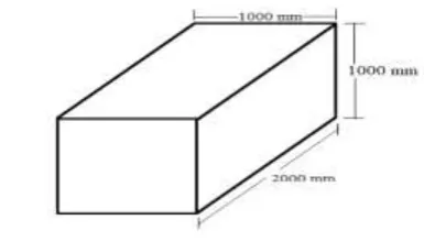
The rectangular pressure vessel is created in ANSYS software and finite element analysis is also done in ANSYS software. Many models have been prepared like with stiffener and without stiffener to compare the stresses in each case. In the design of rectangular pressure vessel width and height is constant in all geometry that is 1000 mm and length is varying from 1000 mm to 10000 mm. The thickness of the rectangular pressure vessel is 50 mm. The stiffeners are used in the prismatic pressure vessel of 100 mm width and 50 mm in height. The stiffeners are added at
and 6-stiffener model are created. One out of ten number of varying length dimension is shown below in Figure 2.1
Figure: 2.1 Dimensions of rectangular pressure vessel
2.4 Modeling
The finite element modelling of rectangular pressure vessel with stiffeners or without stiffeners has been presented in this section for stress analysis. The models of prismatic pressure vessel are shown below in Figure 2.2
(a) (b)
Figure: 2.2 Rectangular pressure vessel models (a) with 0-stiffeners and (b) with 2-stiffeners
[image:2.595.311.551.409.531.2]
(a) (b)
Figure: 2.3 Rectangular pressure vessel models (a) with 4-stiffeners and (b) with 6-stiffeners
[image:2.595.38.284.511.596.2] [image:2.595.309.550.552.674.2]and 6-stiffeners are made at each plate and at equidistant from each other.
The bonded connection is applied in between pressure vessel and cover plate of vessel, it glued together both the contacting surfaces and there is no sliding throughout the analysis process.
2.5 Meshing
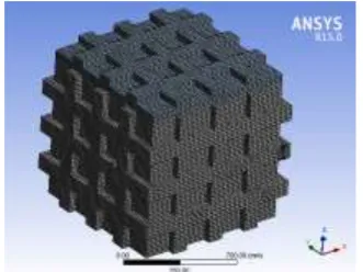
The hex dominant method is used for meshing the rectangular pressure vessel. The mesh size of 20 mm and different number of element and nodes are obtained in different model. The number of nodes and element are shown below in Table 2.2.
[image:3.595.307.558.266.387.2]Figure: 2.4 Meshed model of rectangular pressure vessel
Table: 2.2 Number of Nodes and Elements in rectangular pressure vessel
2.6 Load and Boundary Condition
The fixed boundary condition is applied on one surface of rectangular pressure vessel which is opposite to the cover plate of rectangular pressure vessel. This plane surface is used for the installation of the pressure vessel. The internal pressure of 1 MPa is applied on all the 6 internal faces, five faces from rectangular vessel and one face from cover plate of rectangular pressure vessel. The pressure is acted normal to the selected faces. The load and boundary conditions of rectangular pressure vessel is shown below in Figure 2.5.
Figure: 2.5 Load and Boundary Condition in rectangular pressure vessel
Result
I. Results of Rectangular Pressure Vessel
II Total Deformation
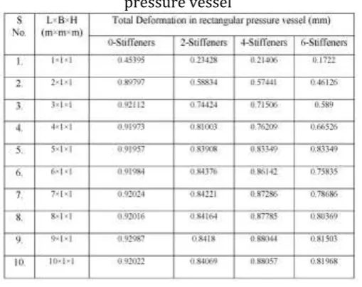
The total deformation in each case of pressure vessel such as with stiffener or without stiffener is shown below in Figure 2.6. It is observed from results that if stiffeners are added in the model of rectangular pressure vessel then total deformation get reduced in comparison to simple pressure vessel. But in case of 2-stiffened and 4-2-stiffened pressure vessel a very little differences occurs in both pressure vessels. Similarly, in all cases the results vary in same manner. The variations in total deformation while increasing the length of the rectangular pressure vessel is shown in Table 2.3.
[image:3.595.79.245.305.429.2] [image:3.595.38.560.512.805.2]
(c) (d)
Figure: 2.6 Total deformation in rectangular pressure vessel (a) with 0-stiffener, (b) with 2-stiffener, (c)
with 4-stiffener and (d) with 6-stiffener.
[image:4.595.36.291.382.584.2]While increasing the length of the pressure vessel, the deformation increases up to 3000 mm and onwards 3000 mm length the deformation is approximately constant in case of simple pressure vessel. But in case of 6-stiffened rectangular pressure vessel, the deformation increases while increasing the length of the rectangular pressure vessel.
Table: 2.3 Total Deformation in all type of pressure vessel
2.6.1 Equivalent Stresses
The equivalent stresses in rectangular pressure vessel is shown in Figure 2.7 it is observed that the equivalent stress is increased up to 2-stiffener and then its value decreases in 4-stiffener and 6-stiffener. The edges of the rectangular pressure vessel is highly stressed region but if stiffeners are made in outer portion of the pressure vessel then high stress region is shifted towards the area of stiffeners.
(a) (b)
(c) (d)
Figure: 2.7 Equivalent Stresses in rectangular pressure vessel (a) with 0-stiffener, (b) 2-stiffener,
(c) 4-stiffener and (d) 6-stiffener.
From the Table 4.4 when we move horizontally in Table 4 then it is observed that the equivalent stresses first increase up to 2-stiffeners and then decreases up to 6-stiffener. When we observed the results in vertical direction then equivalent stresses increases up to 3000 mm length of the rectangular pressure vessel in simple pressure vessel and 2-stiffened pressure vessel. From 4000 mm to 10000 mm stresses increases or decreases. In case of 4-stiffeners and 6-stiffeners equivalent stresses increases up to 4000 mm after that stresses increase or decrease up to 10000 mm.
[image:4.595.309.570.567.736.2]3. Conclusion
The rectangular pressure vessel is used to store the fluid and solid waste substantially different from ambient pressure. The simple and stiffened rectangular pressure vessel with varying length from 1000 mm to 10000 mm. There are 4 models of each length such as simple rectangular pressure vessel, 2-stiffened, 4-stiffened and 6-4-stiffened pressure vessel. All the models are created in ANSYS software. The material chosen for the rectangular pressure vessel is SA-516 Gr. 70.
3.1Total Deformation
The results obtained by comparing the deformations are when the length increases from 1000 mm to 10000 mm, in case of simple pressure vessel deformation increases upto 3000 mm length after that its value decreases or increases, for 2-stiffened pressure vessel deformation increases upto 6000 mm length, for 4-stiffened pressure vessel deformation increases throughout the length and for 6-stiffened pressure vessel deformation value increase upto 5000 mm length and then decreases after that its value increases again. When comparing the deformation for same length, the deformation decreases from simple pressure vessel to 6-stiffened pressure vessel.
3.2 Equivalent Stress
When comparing the equivalent stresses, its value increases upto 3000 mm and then decreases in all length but when comparing the equivalent stresses for the same length and the rectangular pressure vessel with or without stiffeners are maximum in case of 2-stiffened pressure vessel and decreases in 4-2-stiffened and 6-stiffened pressure vessel upto 3000 mm after that the equivalent stress value is same for 2- and 4-stiffened pressure vessel.
References
[1] Y. Choi, J. Ahn, H. You, C. Jo, Y. Cho, Y. Noh, D. Chang, H. Chung and P.G. Bergan “Numerical and Experimental Study of a plate-stiffened prismatic pressure vessel”, Ocean Engineering, 2018, v. 164, pp. 367-376.
[2] S. Chattopadhyay, “Material selection for a pressure vessel”, American Society for Engineering Education, 2008, pp. 1-10.
[3] J.H. Faupel., “Pressure Vessel and Piping Codes”, Journal of Pressure Vessel Technology, 1979, v. 101, pp. 255-267.
[4] R.N. Sen, “INS National Workshop on Pressure Vessels Design and Fabrication”, Indian Nuclear Society, Mumbai, 2011.
[5] D.R. Moss, Pressure Vessel Design Manual, Gulf Professional publishing, USA, 2004.
[6] Info Dunya , (2016, December). Asymmetric Cylindrical Pressure Vessel. Retrieved April 25, 2019, from https://youtu.be/IVXviyD3_nA
[7] B.S. kumar, P. Prasanna, J. Sushma and K.P. Srikanth, “Stress Analysis and design Optimization of a Pressure vessel Using Ansys Package”, Materials today: Proceedings 5, 2018, pp. 4551-4562.
[8] J. lee, Y. Choi, C. Jo and D. Chang, “Design of a Prismatic Pressure Vessel: An Engineering Solution for Non-Stiffened-Type vessels”, Ocean Engineering, 2017, v. 142, pp. 639-649.
[9] D.G. Lokhande and D.V. Bhope, “Stress Analysis of Rectangular Boxes Using Fem”,
BIBLIOGRAPHY