Design of Modified Stewart Platform for Solar Tracing
Applications
N. Mohammed Abu Basim
Assistant Professor
Dept. of Mechanical Engineering
Velammal Institute of Technology
Nishant Sharma R.,
Ashwindh Vignesh A.
BE IV Year
Dept. of Mechanical Engineering
Velammal Institute of Technology
P. B. Dinesh, I. Ajith
BE IV Year
Dept. of Mechanical Engineering
Velammal Institute of Technology
ABSTRACT
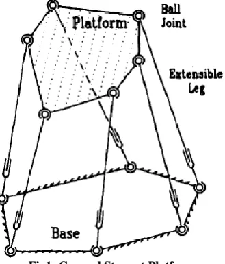
Parallel connection is an exceptional case, where the links and joints are formed in a sequential manner these chains join the base of the manipulator with the end effectors. Stewart Platform is a form of Parallel Manipulator which has a six-degree-of freedom, in parallel linkage. It is utilized in diverse applications requiring linkages with high structural stiffness.. Stewart Platform consists of a rigid platform supported by six variable length struts. Every set of six strut lengths defines a unique, fully constrained position of the platform. Using the strut lengths as controlling input, the position and orientation of the end effectors can be controlled as output. Each leg includes a prismatic joint with ball-joint connection to the base and coupler, respectively. There are almost 64 different configurations; the Stewart Platform can be modified. Here, we try to redefine and redesign the traditional Stewart Platform and use it for very specific application in tracking the sun‘s radiations. The process is done by using Arduino Controller to control the platform with respect to Azimuth angles
Keywords
Parallel Manipulators, Stewart Platforms, Prismatic Joint, Azimuth Angles, Arduino Controller
1.
INTRODUCTION
A linkage is an explained instrument of inflexible connections associated through lower-combine joints. We are keen on linkages shaping at least one kinematic circles, i.e., shut successions of pairwise verbalized connections. This report shows another technique for the position examination of such linkages, that is, for the calculation of the designs they can embrace, inside indicated ranges for their degrees of opportunity. A setup is here comprehended in a kinematic sense: as a task of positions and introductions to all connections that regards the kinematic requirements forced by all joints, with no respect to conceivable connection interface obstructions. A few issues in Robotics interpret into the over one, or require a proficient module ready to illuminate it. The issue emerges, for case, when illuminating the reverse/forward kinematics of serial/parallel controllers [1], [2], when arranging the planned control of a question or the movement of a reconfigurable robot [3], or in synchronous limitation and guide building [4]. The issue additionally shows up in different areas, for example, in the recreation and control of complex deployable structures [5], the hypothetical investigation of inflexibility [6], or the conformational examination of bio-molecules [7]. The shared factor in all cases is the presence of at least one kinematic circles in the framework within reach, characterizing a linkage whose practical designs must be resolved. Parallel topology robots have not yet made a noteworthy affect in modern applications and this is presumably there has been next to no work on the
adjustment of completely parallel controllers. The Stewart stage [8] was initially proposed as a pilot training program stage , and is generally utilized for this today [9] utilized the instrument as a 6 DOF stage for mechanical get together , while [10] connected the component to satellite following . The Stewart stage has likewise been considered for use as a machine instrument.
2.
LITERATURE SURVEY
A few research papers which have headed us to approach for designing a machine which might provide for answer for all these components are as takes after:.
joints. The factors that portray the activated joints will be alluded to as the information factors or likewise as the dynamic joint factors. Different creators allude to in-distinguishable factors from articular directions. Then again, the factors that portray completely the stance of the versatile stage (the end-effectors) will be alluded to as yield factors. At the end of the day, similar factors are alluded to as summed up coordinates. The setup of a n-DOF parallel component isn't characterized by its information factors. The assignment of finding the legitimate arrangement of yield factors comparing to an arrangement of information factors, alluded to as the direct kinematic issue, has as a rule a large number of arrangements, alluded to as get together modes. Truth be told, a few components enable an interminable number of answers for their immediate kinematics—a circumstance alluded to as self-movement [19]. All the more accurately, self-movement implies a limited portability from a few purposes of the workspace, while the confusingly comparable term design peculiarity alludes to a peculiarity in each purpose of the workspace [20]. Whenever, at least two, of the gathering modes are matching, we say that there is a Type 2 peculiarity. The design of a n-DOF parallel component isn't characterized by both the info and yield factors. Undoubtedly, a few components exist which will permit aloof movement notwithstanding when the engines and the portable stage are settled. Such specific singularities are called Redundant Passive Motion (RPM) singularities [21], Most much of the time, in any case, the client and the fashioner of a parallel component will be intrigued just in the arrangement of doable yield factors which we will allude to as the entire workspace. The total workspace of a 6-DOF parallel controller is a six-dimensional exceedingly coupled element which is for all intents and purposes difficult to envision. In this way, the entire workspace of such instruments is considered just through its diverse subsets. The majority of these are likewise characterized for parallel components with under six degrees of flexibility. The most widely recognized subset of the total workspace is the consistent introduction workspace which is the arrangement of admissible positions for the focal point of the versatile stage while the stage is kept at a steady introduction. On the other hand, the introduction workspace is the arrangement of admissible introductions of the portable stage, while the stage focus is held settled.
The dynamic definition and the induction of dynamic conditions for parallel controllers is very convoluted, in light of their shut circle structure and kinematic requirements. In the bland case, the Euler Lagrange detailing with burden of the requirements through Lagrange multipliers brings about an arrangement of differential arithmetical conditions [22] which are very entangled to comprehend. Furthermore, such a plan requires a lot of representative calculation with a specific end goal to ®nd fractional subordinates of the Lagrangian and a lot of numerical calculation to assess those subsidiaries. Interestingly, the Newton Euler definition requires no assessment of subordinates of any useful (like the Lagrangian), and thus deters a ton of lumbering figurings. In the dynamic detailing of open-chain serial controllers, the Newton Euler approach is for the most part limited to the converse progression calculations and isn't highly supported for the induction of shut frame dynamic conditions. Be that as it may, on account of parallel controllers, the Newton±Euler approach can be utilized with the favourable position for inferring shut frame dynamic conditions too. In a past paper [23], the authours built up an e•cient plan for the backwards flow of the Stewart stage controller, through the Newton Euler approach. In the present paper, a similar approach has been
received for building up the shut frame dynamic conditions of the Stewart stage, which are fundamental for forward elements and control framework outline. The Stewart stage is a six-degrees-of-opportunity component with two bodies associated together by six extendable legs. This controlling gadget is acquired from speculation of the instrument proposed by Stewart [24] as a ¯ight test system. The general Stewart stage has a base and a stage associated by six extendable legs{ associated through round joints at the two closures, or a circular joint toward one side and an all inclusive joint at the otherFichter [25] and Merlet [26] talked about the information space to assignment space compel change which can be utilized for dynamic examination of the Stewart stage when leg latency and joint grating are insigni®cant. Sugimoto [27], [28]] considered the opposite progression of parallel controllers when all is said in done through engine polynomial math. Do and Yang [29] tackled the reverse elements for the Stewart stage by the Newton±Euler approach expecting the joints are frictionless and the legs are symmetrical and thin (i.e. the focal point of gravity lies on its pivot and hub snapshot of inactivity is irrelevant). Geng et al. [30] and Liu et al. [31], [32] created Lagrangian conditions of movement under some streamlining presumptions with respect to the geometry and idleness conveyance of the controller. Ji [33] considered the exact of leg idleness on the elements of the Stewart stage.
[35] The authors explain about the eccentricity examination of a 14 composite serial in-parallel six degree-of-freedom robots, Hosting a normal parallel sub instrument flying. It will be showed up that this crew for robots need three normal parallel singularities that are ascribed of the normal unpredictable eccentricity. Those goes something like were affirmed tentatively around a model of a composite serial in-parallel robot that might have been synthesized and based to use over restorative requisitions. [36]demonstrates the working of MIPS which may be a more modest scale robot for a parallel mechanical building hosting three degrees about chance (one elucidation) that tolerance fine situating of a surgical mechanical assembly. That reason from claiming MIPS will go about as an progressive wrist. In the tip from claiming a endoscope which provides an accurate instrument that might also offers fragmentary force-feedback. [37] Presented a circular joint component, an advanced instrument used in executing diverse collocated round joints. [38] Shows about two novel energetic versant Cartesian space control calculations need aid recommended to grinding remittance in the six degrees of adaptability tall execution Stewart stage based machine instruments. The regardless controller uses a versant grinding reward contrives in view of a guessed linear-in-the-parameters grinding demonstrate. In the minute controller, an advanced state of Takagi-Sugeno Multi-Input Multi-Output feathery skeleton is made with adaptively take dark grinding conduct and adjust for it. This approach hope that no one from the earlier majority of the data around frictional affects in the strut joints may be approachable. [39]
Assemblies around rumination In addition two end goal. Contacts to cleared crazy besides straight TMJs. This robot has four degrees. Starting with asserting chance yet every last one of might be driven by six actuators. Every. Prismatic– universal–spherical linkage wills a chance to be generated up of a pivoting. Motor, an prismatic joint, An broad joint, Moreover an round. Joint. The closed-form respond in due order regarding the kinematics will a chance to be. Found. This novel robot will a chance to be evaluated inevitably Tom's examining simulations from asserting kinematics,. Workspace, and an gnawing improvement examination. [41]
Explains about the closed-loop equations for three barrel shaped rollers, the insect from claiming three circular ends, and the lodging of the tripod steady speed joints would deduced as the spatial instrument. They need aid fathomed to endorse positions of its input, and yield shafts furthermore relative movement qualities about parts need aid produced reasonable. Moreover, An methodology may be built for solving, simultaneously, the set from claiming restrictive equations with admiration to drives Also minutes acting around three barrel shaped rollers, the spider, and the housing, for At whatever qualities from claiming rubbing coefficients the middle of barrel shaped rollers Also its grooves
3.
CANONICAL FORMULATION OF
THE DIRECT POSITION
KINEMATICS TO FIND DIFFERENT
CONFIGURATIONS FOR A
GENERAL 6-6 STEWART
PLATFORM [42]
The authors established a well known canonical formulation of the direct position kinematics problem for a general 6-6 Stewart platform with coplanar attachment-points in the base and in the platform. The result will be compelling only if attachment-points in moreover the bottom or the platform are allowed to be non-coplanar. By this formulation, it is revealed that the direct position kinematics problem for the Stewart platform is reduced to the solution of 6 quadratic and 3 linear equations in nine unknowns. This structure has 64 solutions and hence it is over and done with that the 6 -6 Stewart platforms has mainly, 64 assembly configurations.
[image:3.595.85.250.530.723.2]Fig1: General Stewart Platform
Fig 2: Notations & Frames for Reference
Consider a general 6-6 Stewart platform based on the above diagram of randomized geometry with the sole constraint with the intention of the entire 6 base points lie in one plane, referred as base plane and the entire six platforms points also lie in one plane, referred to as the platform plane. The kinematic equations of such a mechanism are derived as follows By Choosing the Coordinate systems of the base frame and the platform frame [which is considered as the reference frame] with their X Y axes in their respective frames. Both the base points and platform points are cited to their body frames, which can be described as
By Choosing the Coordinate systems of the base frame and the platform frame [which is considered as the reference frame] with their X_Y axes in their respective frames. Both the base points and platform points are cited to their body frames, which can be described as
bix
bi = biy (1)
0 Pix
pi = Piy (2)
0
\
where i = 1,2,3....6
leg vectors are referred to base frame as Six
Si = Siy
Siz (3)
where i = 1,2,3....6
Similarly lengths are given as Si = √(Six2 + Siy2 + Siz2)
for i = 1,2,...6 (4)
tx
t = ty
tz
(5) This Equation describes the position of platform with respect to the base.
Relation matrix,
R = [ n 0 a ] = nx ox ax
ny oy ay
nz oz az
The above equation describes the orientation of the platform with respect to the base.
The components of the n, o and vectors are related among the equations by following relations:
n . n = nx 2
+ ny 2
+ nz 2
= 1 7.(a)
o . o = ox2 + oy2 + oz2 = 1 7.(b)
n . o = nxox + nyoy + nzoz = 0 7.(c)
a = n x o 7.(d)
By using transformation
Pi' = RPi + t (8)
where Pi '
is the ith platform point referred to the base frame. The difference of Pi' and bi gives the leg vector Si.
Pi - bi = Si (9) RPi + t - bi = Si (10)
We know that from Equation 4
Si = √(Six2 + Siy2 + Siz2)
From Equation 10
We get,
nxPix + oxPiy + tx- bix = Six
nyPix + oyPiy + ty - biy = Siy
nzPix + ozPiy + tz = Siz
From Equation 4
Si 2 = Six2 + Siy2 + Siz2
Therefore,
(nxPix + oxPiy + tx- bix)2 + (nyPix + oyPiy + ty - biy)2 + (nzPix +
ozPiy + tz)2 = Si 2
Now by the formula of
(a+b+c+d)2 = a2+b2+c2+d2+2ab+2ac+2ad+2bc+2bd+2cd
We get,
(nxPix + oxPiy + tx - bix)2 = nx2Pix2 + ox2Piy2 + tx2 + bix2
+2nxPixoxPiy +2nxPixtx- 2nxPixbix+2oxPiytx- 2oxPiybix- 2txbix (nyPix + oyPiy + ty - biy)2 = ny2Pix2 + oy2Piy2 + ty2 + biy2
+2nyPixoyPiy +2nyPiyty- 2nyPixbiy+2oyPiyty- 2oyPiybiy- 2tybiy (nzPix + ozPiy + tz)
2
= nz 2
Pix 2
+ oz 2
Piy 2
+ tz 2
+ 2nzPixozPiy
+2nzPixtz +2ozPiytz
On combining the equations we get,
Si 2 = nx2Pix2 + ox2Piy2 + tx2 + bix2 +2nxPixoxPiy
+2nxPixtx- 2nxPixbix+2oxPiytx- 2oxPiybix- 2txbix + ny 2
Pix 2
+ oy 2
Piy2 + ty2 + biy2 +2nyPixoyPiy +2nyPiyty- 2nyPixbiy+2oyPiyty-
2oyPiybiy- 2tybiy + nz 2
Pix 2
+ oz 2
Piy 2
+ tz 2
+ 2nzPixozPiy
+2nzPixtz +2ozPiytz
On further simplification we can get
(tx2 + ty2 + tz2) +2Pix(nxtx + nyty + nztz) +2Piy(oxtx + oyty + oztz)
-2bix(tx+Pixnx+Piyox) - 2biy(ty+Pixny+Piyoy) + bix 2
+ biy 2
+ Pix 2
+ Piy2 - Si2 = 0
(11)
for i = 1,2,3...6.
Considering the Equations 7 and11 which gives the quadratic equations in nine unknowns,{tx, ty, tz, nx, ny, nz, ox, oy, oz} by
carefully noticing the equations, the components of 'a' vector being automatically eliminated.
In the direct kinematics problems, it is required to solve these simultaneous equations for given Si, where i =1,2,3,4,5,6.
from the equation 11, we can see that there are three different groups namely
1. (tx2 + ty2 + tz2)
2. (nxtx + nyty + nztz)
3. (oxtx + oyty + oztz)
These are actually the Square of the magnitude of the translation vector and its component along "X" & "Y" axes. Due to the significance of the equation, we can utilize 3 out of
6 equations, solve them for these 3 groups as linear combinations of variables, tx, ty, nx, ny, ox, oy and put them
in major 3 equations to get them linearised.
Considering only one leg, say leg number 1 and their X axes Along the lines joining their origins to the corresponding ends of the second leg. The Y axes of the frame are automatically set at right angles to the corresponding X-axis in respective planes. Based on the reference, the first base point lies at the origin of the base frame and second base point lies on its X axis.
b1x = b1y = P1x = P1y = b2y = P2y = 0 (12)
Based on the Equation 12 and using this in equation 11 for the case i = 1,
the first leg equation is
tx 2
+ ty 2
+ tz 2
= Si 2
(13)
Using equation 13 in equation 11
P1x(nxtx+ nyty+nztz) + P1y(oxtx+oyty+oztz) -b1x(tx+P1xnx+P1yox) b1y(ty+P1xny+P1yoy) = K1
(14) where
K1 = (Si2 - bix2 - biy2 - Pix2 - Piy2 - Si2 ) / 2 (15)
By using Equation 12 & 14, for i=2, the second leg equation becomes
P2x(nxtx+ nyty+nztz) -b2x(tx+P2xnx) = K2 (or) P2x(nxtx+ nyty+nztz) =K2 + b2x(tx+P2xnx)
(nxtx+ nyty+nztz) = ( K2/ P2x ) + {[ b2x(tx+P2xnx) ]/ P2x} (16) = ( K2/ P2x ) + {(b2x tx)/ P2x} + {( b2x P2xnx)/ P2x} = A + A1 tx + A2 nx
Where,
A = K2/ P2x A1 = b2x/ P2x A2 = b2x
Note : P2x should not be Zero
Now using Equation 16 in Equation 14 to get K3.
P3x[ ( K2/ P2x ) + {(b2x tx)/ P2x} + ( b2x nx) ] + P3y
[oxtx+oyty+oztz] - b3x(tx+P3xnx+P3yox) - b3y(ty+P3xny+P3yoy) =
K3
P3y [oxtx+oyty+oztz] = K3 + b3x(tx+P3xnx+P3yox) +
b3y(ty+P3xny+P3yoy) - P3x [(K2/P2x ) + {(b2x tx)/ P2x} + ( b2x nx) ]
= K3 + b3x tx + b3x P3xnx+ b3x P3yox + b3y ty+ b3y P3xny+ b3y
P3yoy - P3x[(K2/P2x ) + {(b2x tx)/ P2x} + ( b2x nx) ]
[oxtx+oyty+oztz] = (K3/P3y) + (b3x tx/P3y) + (b3x P3xnx/P3y)
+ (b3x P3yox/P3y) + (b3y ty/ P3y) + (b3y P3xny/ P3y )+ (b3y P3yoy /
[oxtx+oyty+oztz]= B1tx + B2nx +B3ox + B4ty + B5ny + B6oy +B '
(17)
Where,
B1 =( b3x P2x - P3x b2x)/ P2x P3y B4 = b3y/P3y
B2 = {[P3x (b3x- b2x)]/P3y} B5 = (b3x P3x)/P3y B3 = b3x
B6 = b2y
B' = { (K3P2x - P3xK2)/ P2x P3y }
Note: In all the 'B' values,B1, B2, B3, B4, B5, B6, B', the P3y should be non-zero.
This indicates that the third platform point should be chosen Non-collinear with the first two.
P4x(nxtx+ nyty+nztz) + P4y(oxtx+oyty+oztz) -b4x(tx+P4xnx+P4yox) - b4y(ty+P4xny+P4yoy) = K4
Now substitute the values of (nxtx+ nyty+nztz) & (oxtx+oyty+oztz)
P4x[A + A1 tx + A2 nx] + P4y[ B1tx + B2nx +B3ox + B4ty + B5ny + B6oy +B
'
] - b4xtx - b4xP4xnx - b4xP4yox - b4yty - b4yP4xny - b4yP4yoy = K4
Expanding all the terms we get,
[P4xA1 + P4yB1 - b4x] tx + [P4xA2 + P4y B2 - b4xP4x] nx + [P4y B3 - b4xP4y] ox + [P4y B4 - b4y] ty + [P4yB5 - b4yP4x] ny + [P4y B6 - b4yP4y] oy + P4xA + P4yB' = K4
Therefore,
K4 = C6tx + C5nx +C4ox + C3ty + C2ny + C1oy + P4yB '
+ P4xA
Where,
C6 =(P4xb2x/ P2x) + (P4yb3x/P3y) - (P4yb2xP3x/P2xP3y) - b4x C5 = P4xb2x + (P4yP3xb3x)/P3y - (P4y P3xb2x)/P3y -b4xP4x C4 = P4yb3x - b4xP4y
C3 = {(P4yb3y)/P3x}- b4y C2 = {(P4yb3yP3x)/P3y }- b4yP4x C1 = P4y[b3y - b4y]
B = (K3P2x - K2P3x)/(P2xP3y) A = K2/P2x
Similarly,
K5 = D6tx + D5nx +D4ox + D3ty + D2ny + D1oy + P5yA + P5xB
Where,
D6 =(P5xb2x/ P2x) + (P5yb3x/P3y) - (P5yb2xP3x/P2xP3y) - b5x D5 = P5xb2x + (P5yP3xb3x)/P3y - (P5y P3xb2x)/P3y b5xP5x D4 = P5yb3x - b5xP5y
D3 = {(P5yb3y)/P3x}- b5y D2 = {(P5yb3yP3x)/P3y }- b5yP5x D1 = P5y[b3y - b5y]
B = (K3P2x - K2P3x)/(P2xP3y) A = K2/P2x
Similarly,
K6 = E6tx + E5nx +E4ox + E3ty + E2ny + E1oy + P5yA + P5xB
Where,
E6 =(P6xb2x/ P2x) + (P6yb3x/P3y) - (P6yb2xP3x/P2xP3y) - b6x E5 = P6xb2x + (P6yP3xb3x)/P3y - (P6y P3xb2x)/P3y - b6xP6x E4 = P6yb3x - b6xP6y
E3 = {(P6yb3y)/P3x}- b6y E2 = {(P6yb3yP3x)/P3y }- b6yP6x E1 = P6y[b3y - b6y]
B = (K3P2x - K2P3x)/(P2xP3y)
A = K2/P2x
Rewriting all the Equations,
nx2 + ny2 + nz2 = 1 ox2 + oy2 + oz2 = 1 nxox+nyoy+nzoz = 0 tx2 + ty2 + tz2 = S12 nxtx + nyty + nztz= A + A1 tx + A2 nx
oxtx+ oyty+ oztz = B1tx + B2nx +B3ox + B4ty + B5ny + B6oy +B'
K4 = C6tx + C5nx +C4ox + C3ty + C2ny +C1oy + P4yB' + P4xA
K5 = D6tx + D5nx +D4ox + D3ty + D2ny + D1oy + P5yA+ P5xB
K6 = E6tx + E5nx +E4ox + E3ty + E2ny + E1oy + P5yA + P5xB
The above equations represent the canonical equations for the forward displacement analysis of the Stewart platform. These constitute a system of six quadratic and three linear equations and hence will have 2 ~ or 64 solutions in general. Thus, it is shown that a Stewart platform of general geometry has at most 64 configurations for a set of given leg-lengths, and cannot have more. These 64 configurations will, of course, occur in 32 pairs, each member of one pair being the mirror image of the other member of the same pair about the base plane.
4.
WORKING
The Stewart platform consists of two circular plate, 6-servo motors, 6-connecting rod, l-clamp, arduino board, solar panel. The circular plates are placed parallel to each other in which the plates are in the ratio of 2:1. The circular plates are made up of acrylic material which is a thermoplastic material combining of high strength and ductility. The servo motors are mounted on the base plate with an angle of 60 degree. These motors are placed above the base plate at a height of 500mm.
Three L-clamps are mounted on the upper plate at an angle of 120 degree each. The Wheel spokes is used as a connecting rod between the L-clamp and servo motors. One end of connecting rod is connected to the L-clamp and other end is connected to the servo motor crank where the connecting rod converts the rotary motion into reciprocating motion. Servo motors are connected to arduino board. Arduino board is a type of dsPIC microcontroller which consists of software that runs the programs. An object can possess 6-dof only when it is in space suspended freely without any constraints in it. The Stewart platform has the advantage of providing 6 dof considering the object does not need to be in space.
travelled by the sun making it as a triangle format and from that the angle can be measured.
[image:6.595.55.548.83.350.2]A, B, C, D, E, F are the servo motors which are projected with the respective angle inclined corresponding to the solar tracing. Fig 3: The LED screen helps us to view the position of each servo motor positioned, the respective view of the Modified Stewart
Platform is also shown beside the screen for better understanding and view of the observer.
Our project brings about the same concept as discussed below. In this project a solar panel is placed at the top plate of the Stewart platform. A microcontroller is used to control the rotation of the motors. The connecting rod is used to provide support according to the movement of the top plate. The input is given to the ssAs this connecting rod moves the top plate moves corresponding to the rods in a way providing the 6-dof. The angle provided by the connecting rod is the exact angle as azimuth angle. The servo motors are provided at the bottom plate of the platform. The servo motors are closed loop control system in which the output is based on input feedback. The servo motor has the advantage of providing maximum torque for rotating the connecting rod. The solar panel which is placed on the top plate is rotated according to the azimuth angle in which maximum amount of solar energy can be acquired and this solar energy can be stored to convert it into electricity.
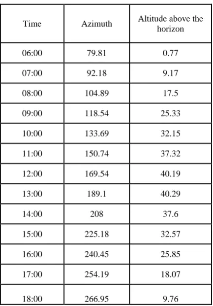
An azimuth is an angular measurement in a spherical coordinate system. The vector from an spectator (origin) to a position of attention is predictable perpendicularly on top of a reference plane; the angle stuck between the projected vector and a reference vector on the reference plane is called the ―azimuth‖. An example of azimuth is the angular route of a star in the sky. The star is the point of interest, the reference plane is the local horizontal area (e.g. a circular area 5 km in radius around an observer at sea level), and the reference vector points north. The azimuth is the angle between the north vector and the star's vector on the horizontal plane. Azimuth is usually measured in degrees (°). The concept is used in navigation, astronomy, engineering, mapping, mining, and ballistics.
Table 1: Sun’s Position- Azimuth Angles
Time Azimuth Altitude above the horizon
06:00 79.81 0.77
07:00 92.18 9.17
08:00 104.89 17.5
09:00 118.54 25.33
10:00 133.69 32.15
11:00 150.74 37.32
12:00 169.54 40.19
13:00 189.1 40.29
14:00 208 37.6
15:00 225.18 32.57
16:00 240.45 25.85
17:00 254.19 18.07
[image:6.595.314.531.417.728.2]5.
RESULT AND DISCUSSION
The principle behind the work is to afford a realistic instruction for the edifice the GSPs with auxiliary reference for an concerned reader. The fundamental hypothesis together with the IK solution for the meticulous case of a GSP with permanent rotary actuators was presented. The constructed archetype was deliberately built out of commercially accessible low cost structure blocks in order to disembark at the concluding design quickly. No supplementary effort was put into a defined assessment of the prototype. A coarse-grained evaluation of the workspace, orient ability, speed and load-carrying capacity is prearranged in the previous section. The achieved design is inevitable for any particular purpose but is supposed to serve as a ―rapid prototyping‖ illustration of a successful low cost and effusive operational GSP construction. At the current stage the prototype is certainly not precise enough for MIS robotics in whose context the application of the SPs was discussed. Speed, accuracy and load-carrying capacity can all be enhanced easily by replacing the analog servos with digital ones. However, for an application in medical robotics a different architectural design with prismatic piezoelectric actuators is considered.
6.
CONCLUSION AND FUTUTRE
SCOPE
Based on the above speculation, the paper clearly states one of the diverse applications in Stewart Platform. Various literatures are available for explaining the methods to trace the path of the sun, but the method we had proposed is entirely simple through which maximum efficiency can be obtained. The platform is designed to occupy the majority of the radiations to be fallen on the solar plate. Maximum efforts have been done to remodel the top platform in a hemispherical manner, but due to the complexity it is designed in a circular fashion. The project mainly focus on the application leaning towards Stewart Platform and not on the kinematic and dynamic analysis nor any mathematical modelling, but the paper briefly discuss about the canonical formulation of the direct position kinematics problem for a general 6-6 Stewart platform with coplanar attachment-points in the base and in the platform, through which the number of configurations have been well defined. The future scope of the project basically lies on the analysis of the joints used; it can be universal, prismatic or rolling joints. Stewart platforms have application in full flight simulator for which all 6 DOF are required, appliance tool technology, hoist technology, submerged research, air-to-sea rescue, mechanical-bulls, satellite dish positioning, telescopes and orthopaedic surgery. The Computer Assisted Rehabilitation Environment (CARE) urbanized by Motek Medical use a Stewart platform tied with virtual reality to perform sophisticated biomechanical and clinical research. Dr. J. Charles Taylor utilizes the Stewart platform to develop the ―Taylor Spatial Frame‖ which is an external fixture second-hand in orthopaedic surgery for the modification of bone deformity and dealing with complex fractures. A 4‐UPS‐UPU 5‐Degrees of Freedom PCMM (Parallel coordinate measuring machine), which can attain 3 transformation DOF and 2 rotational DOF
7.
REFERENCES
[1] D. Manocha and J. Canny. Efficient inverse kinematics for general 6R manipulators. IEEE Transactions on Robotics and Automation, 10:648–657, 1994.
[2] J.-P. Merlet. Parallel Robots. Springer, 2000.
[3] J. H. Yakey, S. M. LaValle, and L. E. Kavraki. Randomized path planning for linkages with closed
kinematic chains. IEEE Transactions on Robotics and Automation, 17(6):951–958, 2001.
[4] J. M. Porta. CuikSlam: A kinematics-based approach to SLAM. In IEEE International Conference on Robotics and Automation, pages 2436–2442, 2005.
[5] P. Kumar and S. Pellegrino. Computation of kinematic paths and bifurcation points. International Journal of Solids and Structures, (37):7003–70027, 2000.
[6] C. Borcea and I. Streinu. The number of embeddings of a minimally-rigid graph. Discrete and Computational Geometry, 31(2):287–303, 2004.
[7] W. J. Wedemeyer and H. Scheraga. Exact analytical loop closure in proteins using polynomial equations. Journal of Computational Chemistry, 20(8):819–844, 1999. [8] .D . Stewart , ‗‗A Platform with Six Degrees of Freedom‘‘
Proc . IMechE ( London ) 180 , Part 1 , No . 15 371 – 386 (1965) .
[9]. H . McCallion , and D . T . Pham , ‗‗The analysis of a six degree of freedom work station for mechanised assembly‘‘ 5 th World Congress on Theory of Machines and Mechanisms (1979) . pp . 611 – 616 .
[10] . G . R . Dunlop , P . J . Ellis and N . V . Afzulpurkar , ‗‗The satellite tracking keyhole problem : a parallel mechanism mount solution‘‘ IPENZ Trans . 20 No 1 EMCh , 1 – 7 (1993) .
[11]Stewart, D., 1965. ―A platform with six degrees of freedom‖. Proceedings of the Institution of Mechanical Engineers, 180, pp. 371–386.
[12] Dasgupta, B., and Mruthyunjaya, T. S., 2000. ―The Stewart platform manipulator: a review‖. Mechanism and Machine Theory, 35(1), pp. 15–40.
[13] McInroy, J., and O‘Brien, G., 1999. ―Precise, fault-tolerant precision pointing using a Stewart platform‖. IEEE/ASME Transactions on Mechatronics, 4, pp. 91– 95.
[14] Preumont, A., Horodinca, M., Romanescu, I., de Marneffe, B., Avraam, M., Deraemaeker, A., Bossens, F., and Hanieh, A., 2007. ―A six-axis single-stage active vibration isolator based on Stewart platform‖. Journal of Sound and Vibration, 300, pp. 644–661.
[15] Shaw, D., and Chen, Y., 2001. ―Cutting path generation of the Stewart platform-based milling machine using an endmill‖. International Journal of Production Research, 39, pp. 1367–1383.
[16] van Silfhout, R. G., 1999. ―High-precision hydraulic Stewart platform‖. Review of Scientific Instruments, 70, pp. 3488–3494.
[17] Shoham, M., Burman, M., Zehavi, E., Joskowicz, L., Batkilin, E., and Kunicher, Y., 2003. ―Bone-mounted miniature robot for surgical procedures: Concept and clinical applications‖. IEEE Transactions on Robotics and Automation, 19(5), October.
[18] Cort´es, J., and Sim´eon, T., 2003. ―Probabilistic motion planning for parallel mechanisms‖. In Proc. of the Int. Conf. on Robotics and Automation, Vol. 3, pp. 4354– 4359
Robot Kinematics, Kluwer Academic Publishers, pp. 339-348.
[20]. Ma, O., Angeles, J., 1992, "Architecture Singularities o f Platform Manipulators", Proceedings of the IEEE International Conference on Robotics and Automation, Sacramento, CA, USA, April 11-14, pp. 1542-1547. [21]. Zlatanov, D., Fenton, R.G., Benhabib, B., 1994,
"Analysis of the Instantaneous Kinematics and Singular Configurations of Hybrid-Chain Manipulators," Proceedings of the ASME 23rd Biennial Mechanisms Conference, DE-Vol. 72, Minneapolis, MN, USA, September 11-14, pp. 467-476.
[22]. Meirovitch, L., Methods of Analytical Dynamics, McGraw Hill, New York, 1970.
[23]. Dasgupta, B. and Mruthyunjaya T. S., Advances in Mechanical Engineering, Proceedings of the International Conference of Advances in Mechanical Engineering, Vol. 1, ed: T. S. Mruthyunjaya. Narosa Publishing House, New Delhi, India, 1996, 199±218.
[24]. Stewart, D., in Proceedings of the Institute of Mechanical Engineerrs, Vol. 180, 1965±66, pp. 371±386. [25]. Fichter, E. F., International Journal of Robotics
Research, 1986, 5(2), 157±182.
[26]. Merlet, J. P., Parallel manipulators part 1: theory. design, kinematics, dynamics and control, INRIA Report, 1987. [27]. Sugimoto, K., Transactions of ASME, Journal of
Mechanism, Transmission and Automation in Design, 1987, 109, 3±7.
[28]. Sugimoto, K., Transactions of ASME, Journal of Mechanism, Transmission and Automation in Design, 1989, 111, 29±33.
[29]. Do, W. Q. D. and Yang, D. C. H., Journal of Robotic Systems, 1988, 5(3), 209±227.
[30]. Geng, Z., Haynes, L. S., Lee, J. D. and Carroll, R. L., Robotics and Autonomous Systems, 1992, 9, 237±254. [31]. Liu, K., Fitzgerald, M., Dawson, D. W. and Lewis, F. L.,
ASME DSC, Control of Systems with Inexact Dynamic Models, 1991, 33, 83±89.
[32]. Liu, K., Lewis, F., Lebret, G. and Taylor, D., Journal of Intelligent Robotic Systems, 1993, 8, 287±308.
[33]. Ji, Z., Transactions of ASME, Journal of Mechanical Design, 1994, 116, 67±69.
[35] Simaan And Shoham: Singularity Analysis Of A Class Of Composite Serial In-Parallel Robots, Ieee Transactions On Robotics And Automation, VOL. 17, NO. 3, JUNE 2001
[36] Jean-Pierre Merlet, Micro parallel robot MIPS for medical applications DOI: 10.1109/ETFA.2001.997742 · [37] Paul Bosscher Imme Ebert-Uphoff, A Novel Mechanism
for Implementing Multiple Collocated Spherical Joints Proceedings of the 2003 IEEE International Conference on Robotics & Automation Taipei, Taiwan, September 14-19, 2003
[38] Denis Garagić and Krishnaswamy Srinivasan,
Contouring Control Of Stewart Platform Based Machine Tools Proceeding of the 2004 American Control Conference Boston, Massachusetts June 30 - July 2, 2004 [39] N. Sims‘an, D. Glozman, M. Shoharn, DESIGN CONSIDERATIONS OF NEW SIX DEGREES-OF-FREEDOM PARALLEL ROBOTS, Proceedings of the 1998 IEEE International Conference on Robotics& Automation
[40] Haiying Wen, Weiliang Xu, and Ming Cong Kinematic Model and Analysis of an Actuation
Redundant Parallel Robot With Higher Kinematic Pairs for Jaw Movement IEEE TRANSACTIONS ON INDUSTRIAL ELECTRONICS, VOL. 62, NO. 3, MARCH 2015
[41] Katsumi Watanabe, Tsutomu Kawakatsu
Shouichi Nakao Kinematic and Static Analyses of Tripod Constant Velocity Joints of the Spherical End Spider Type NOVEMBER 2005, Vol. 127 / 1137