Viewfinder: final activity report
PENDERS, Jacques <http://orcid.org/0000-0002-6049-508X>
Available from Sheffield Hallam University Research Archive (SHURA) at:
http://shura.shu.ac.uk/2171/
This document is the author deposited version. You are advised to consult the
publisher's version if you wish to cite from it.
Published version
PENDERS, Jacques (2010). Viewfinder: final activity report. Project Report. Sheffield
Hallam University, Materials and Engineering Research Institute. (Unpublished)
Copyright and re-use policy
See http://shura.shu.ac.uk/information.html
Final Activity Report
Final
Version 12-07-10
1 December 2006 - 30 November 2009
F
INAL
R
EPORT
Version 12-07-10
Abstract ... 4
Conclusions ... 5
Crisis management ... 6
Feedback from Fire fighters ... 6
Crisis management, description ... 7
Incident Command structure ... 8
Incident Risk Assessment ... 9
Disaster Management Action Plan (DMAP) and Crisis Management Information System (CMIS) .... 9
Further reading ... 10
Base Station ... 10
Base station baseline concept ... 10
Base station, set up and innovation ... 12
Literature background ... 12
Base station set up and innovation ... 13
Further reading ... 15
Communication Network ... 15
Further reading ... 17
Chemical Sensors ... 17
Further Reading ... 20
Map Building and Reconstruction ... 20
Indoor ... 20
System Overview... 20
Slam-2D ... 21
Point cloud / image acquisition ... 22
Fusing image and point cloud in 3D ... 23
Processing of the resulting point cloud in 3D ... 24
Visual Simultaneous Localization and Mapping ... 25
Dense 3D Reconstruction ... 26
Stereo vision ... 26
Victim detection ... 27
Further Reading ... 27
Robot Platforms and Middleware ... 29
Software Architecture ... 29
Robot Navigation ... 30
Behavior-based Robot Control ... 30
Further Reading ... 31
Direct human Robot Interaction ... 32
Conceptual Design ... 32
Further Reading ... 34
Abstract
The VIEW-FINDER project (2006-2009) is an 'Advanced Robotics' project that seeks to apply a semi-autonomous robotic system to inspect ground safety in the event of a fire. Its primary aim is to gather data (visual and chemical) in order to assist rescue personnel. A base station combines the gathered information with information retrieved from off-site sources
The project addresses key issues related to map building and reconstruction, interfacing local command information with external sources, human-robot interfaces and semi-autonomous robot navigation.
Conclusions
Fire fighters have intrinsically been involved in evaluating the project results. The overall feedback is that it was of significant benefit. Frequent interaction with fire fighters enabled the project team to understand how the developed devices and algorithms could be incorporated into the current practise of incident management.
The project produced an ergonomic base station for human robot interfacing, in terms of effectiveness, efficiency and user satisfaction, the results look promising.
The Mailman communication system manages the quality of service and traffic prioritization on the wireless communication connection. For interactive robot control (tele-operation) 100 msec latency is accepted while between human interfaces at the base station and robot latency may stretch to 1 second.
The chemical sensors combine off-the-shelf (metal oxide) MOS sensors and in-house developed quartz crystal based sensors (QCM). The QCM sensors provide the necessary sensing at higher concentration around the upper explosive level (UEL) for which the MOS sensors are not very suitable.
For map-building, we analysed and implemented a range of methods and algorithms. Direct robot navigation uses a 2D SLAM procedure (occupancy grid) in the indoor scenario and a Visual-SLAM method for the outdoor scenario. The 3D data representations are used for remote inspection.
For indoor application a laser range finder on a tilt mechanism produces a 3D point cloud which is fused with a camera image. The number of tilt moves determines the acquisition speed. Indicatively, for 10 tilt moves, it takes about 1.2 seconds to acquire the 3D scene. In that respect we had to adapt/develop Player drivers (issues with temporary buffering in existing ones) and method for acquiring a 3D representation. A technique to reconstruct a scene from the acquired point clouds in 3D has been presented; this also focuses on real-time capabilities.
For the outdoor application, we developed a dense stereo approach which mixes fast-but-incomplete stereo data with camera motion information and anisotropic diffusion resulting in a dense depth reconstruction at near real-time frame-rates. For robot navigation we apply a
classification of the terrain into ―traversable‖ and ―obstacle‖. Problems in image quality due to
robot‘s locomotion have been investigated and active stabilization solutions have been
provided. The developed algorithm consists of a stereo algorithm, able to provide reliable depth maps of the scenery in frame rates suitable for a robot to move autonomously. The said algorithms are capable of adapting to non-ideal lighting conditions. A second building block is a decision-making algorithm that analyzes the depth maps and deduces the most appropriate direction for the robot to avoid any existing obstacles.
The results obtained during a real crisis management exercise, show that the visual
reconstruction outputted by the presented method, can increase the situational awareness of the human crisis managers by integrating localized information on the 3D model.
The architecture for the indoor mobile robot provides compatibility between several
Several prototypes for a direct human robot interface have been built and tried with experienced fire fighters. Overall we feel this work demonstrates the effective use of user centred design concepts in a highly technical development project that includes both safety critical user interface design to underpin advanced robotic technology.
Crisis management
Feedback from Fire fighters
In the course of the ViewFinder project we have cooperated with South Yorkshire Fire and Rescue (they are project partners) as well as with several other fire brigades. South Yorkshire Fire and Rescue were involved from the definition and proposal phase of the project as end-user advisor. They have organised a one dayfire training at the kick-off of the Guardians and ViewFinder projects. The project members experienced this as very useful as it shaped their perception of what a rescue operation involves. In return, the final
demonstrations of the Guardians and ViewFinder were organised at the training station of South Yorkshire Fire and Rescue. Below are the major comments received from fire fighters reflecting on the research work.
The overall comment of South Yorkshire Fire and Rescue about their involvement in the Guardians as well as the ViewFinder projects is the following. As a Fire Brigade we do not have the means to be at the forefront of science and technology developments. However, we are looking at technology to help us improve our service. Improvements can be in risk assessment as well as direct support for the rescue operation. Being involved in these projects has made our officers better aware of available and up-coming technologies. The final demonstrations at our premises certainly got more of our staff involved to look at what was available.
Comments on the technology. Committing Human Fire Fighters to explore a building in an incident requires extensive risk assessment. Risks have to be negotiated with what results could be expected. If human life can be saved some risk is acceptable, if property can be saved very little risk will be taken. When committing a (tele-operated) a robot much more risk can be taken, and this could have a considerable impact on how to deal with the incident. The attack of a building in fire will usually be confined to operations taking place outside the building. In most cases there is no information on what is going on inside, except for what can be observed from the outside. Views from inside would allow more effective attacks..
South Yorkshire Fire and Rescue have developed a new Command Support Vehicle. The main idea behind this vehicle is to collect from and distribute to the officers (on site as well as off site) relevant and up-to-date information about the incident. A robot providing views from inside would enrich our knowledge base. Also the base station developed would also be very well situated in this vehicle.
Risk assessments relating to the possible presence of Hazardous Chemicals are very time consuming, robots with a mobile detection unit would certainly speed this up. The QCM chemical sensors have been designed for in-situ detection of low as well as high concentration of VOCs and toxic gases. Applied on a robot we can take more risks and contamination and in particular decontamination would not be as a big an issue as it is related to human beings.
Crisis management, description
The objective of the VIEW-FINDER project is to develop robots for assistance in the event of an emergency. Rescue operations are regulated and organised following a system of rules for the different authorities that may possibly be involved. To apply robots we therefore have to make sure that we comply with this overall structure. Below we will first briefly explain the procedure etc that apply and next go into the developments resulting from the ViewFinder project.
In case of an emergency an incident management structure is activated and a management authority is established at a predefined level. The level depends on the size of the
emergency.
- evel is activated when the threat or the emergency situation is limited to the local area.
- vel: This level is activated when the threat or emergency situation concerns more than one local authority.
- for very large emergencies.
Each level of authority is required to inform the others in the hierarchy and to keep them informed. The head of the local authority reports to the head of the region and so on.
The Operational Coordination is assured by the operational authority; it is put in place at the intervention site and must be accessible and recognizable by the emergency services. The Operational Coordination coordinates the disciplines which will participate in the
management of the emergency situation, and gather the leaders of these disciplines, as well as the representative of the sinister victims (institution or enterprise), when it is applicable.
[image:8.595.138.462.500.692.2]The intervention site may be partitioned into classified emergency zones. An emergency zone is a sector for which, according to a particular risk, the protective measures for the population have been fixed in advance in the emergency plan. This sector is delimited according to a concrete emergency situation; in it the necessary decisions are taken and executed.
Figure 1, Zonal partitioning of an Incident Area
Depending on the emergency situation, the zones are classified in:
Orange zone (insulation perimeter): accessible to the people who reside or work on this zone. In this zone the logistical support for the intervention services is organized. Yellow zone (dissuasion perimeter): the access is unadvised to people not residing or
working in this zone, in order to facilitate the access of the intervention services. Medias can reach this zone.
The red zone is often the domain of the Fire and Rescue services, who will apply the robots. Below we further detail the command structure for Fire and Rescue services.
The View-finder consortium was able to organise a wide spectrum of end-users including Fire and Rescue Services. Though our aim has never been to carry out a full survey across Europe, the discussions of the user requirements with Belgian, English, Greek Cypriot, Italian, Polish and Spanish rescue services indicate quite a consensus.
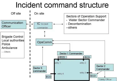
Incident Command structure
When an incident is reported a first appliance is sent to the site. The standard appliance for South Yorkshire Fire and Rescue (SYFIRE) carries a crew of 5 fire fighters including a crew commander (local term: Crew Manager). The crew commander is automatically designated the Incident Commander (IC).
When the incident turns out to require more resources, calls for assistance are made. With the arrival of more appliances and crew the role of Incident Commander is passed on to senior officers and a further division of labour and command occurs.
The early phase of a major incident is very dynamic and neither the Fire Service nor the police will at the early stage have the appropriate amount of personnel present. With the arrival of more personnel the appropriate command structure will be built up.
At larger incidents and depending on the particulars of the incident, specific areas of resource control may be delegated to appointed officers. A very frequently occurring delegation for control is established by defining Operational sectors, refer to Figure 2. The site is divided into sectors with sector commanders. A sector may comprise one or more hose teams, ladder teams and one or more entry points for fire-fightersequipped with Breathing Apparatus (BA) to enter. Each entry point has an 'Entry Control Officer'.
Operational sector commanders are physically located at and should stay in their sector to provide visible leadership.
The span of control for any officer is arranged to be between 3 and 5 lines of
Figure 2, Incident Command Structure
Incident Risk Assessment
Risk assessment is a crucial activity of the Incident Command team, operational decisions are made based on weighting risks and aiming to control risks.
- Fire-fighters will take some risk to save saveable lives. - Fire-fighters will take a little risk to save saveable property.
- Fire-fighters will not take any risk at all to try to save lives or property that are already considered lost.
The key elements of any assessment of risk are:
- Identification of the hazards;
- Assessment of the risks associated with the hazards; - Identification of who is at risk;
- The effective application of measures that control the risk.
Disaster Management Action Plan (DMAP) and Crisis Management
Information System (CMIS)
crucial information, walkthroughs, and scenarios, which guide them through the management process of a crisis. The DMAP provides three types of information:
1. Standards and Terminology: The available standards and terminology ought to facilitate the communication between the involved personnel in very heterogeneous contexts. They include glossaries and industrial standards about dangerous products which might be found on the emergency ground, national and international legislation and regulations with regard to emergency management, information about
emergency management organizations, etc.
1. Crisis event walkthroughs: These walkthroughs are particular recommended procedures and methods to manage a particular crisis, measures for manipulating dangerous products and directives and recommendations to deal with them, list of authorities involved in different crisis situations, etc.
2. Mission templates: The mission templates consist of pre-compiled, standardized tools facilitating the work of the emergency workers and crisis managers. They also include guides and situations, gathered from users, which will orient the emergency workers and crisis managers by proposing pre-recorded situations of similar
emergencies with the adequate solutions provided (lessons learned) to this particular case.
The Crisis Management Information System (CMIS) is a powerful tool for preparation, analysis and response to disaster:
– As a geographic information system (GIS), the CMIS intends to provide the
management experts with geographical details about potential threads and hazards, as the View-Finder system collects data from the field via mobile robot‘s sensors. – As management tool the CMIS enables the data representation, conveying and
visualization in support to Crisis management
On site the natural place for the DMAS and CMIS is at the level of the Incident Commander. Off site it will be available for the higher level crisis management authorities.
Further reading
H. De Smet, C. Pinzon, J. Leyson, Robotic senses for hostile sites. in Crisis Response Journal, Vol. 5, Issue 3, June 2009
Grzegorz Kowalski, Janusz Będkowski, Piotr Kowalski, Andrzej Masłowski :Aid of Computer Training in Handling with Ground Teleoperated Robots for demining, Handbook ‗Emerging sensor and Robotics Technologies for Risky Interventions and Humanitarian de-mining (a book series on Mobile Service Robotics published by Woodhead Publishing Company-UK ) in current edition,
H. De Smet, C. Pinzon, J. Leysen, Y. Baudoin (RMA), J. Gancet (SAS), and J. Penders (SHU), The Disaster Management Action Plan proof-of-concept of a Key Management Tool for Emergency Situations. in IARP/EURON RISE'2009, 12-14 Jan 2009, Brussels, Belgium H. De Smet, C. Pinzon, J. Leyson, Robotic senses for hostile sites (part 2). in Crisis
Response Journal, Vol. 6, Issue 1, Dec2009 (accepted , not published so far) and ... (part 3) in Vol 6, Issue Jun 1010
SyFire (Guardians, View-Finder): Service looks to the future with robot technology', Fireflash: South Yorkshire Fire and Rescue staff magazine, Autumn 2009, p.9
Base Station
Base station baseline concept
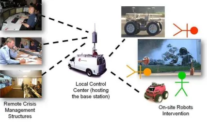
located inside an advanced outpost, close to the intervention site. A View-Finder appliance typically comes as a mid-size truck carrying both the base station, the equipped robots, the communication means (e.g. communication antennas for the robots, organization dedicated communication means) and the human crew. Once on site, the robots and communication means are deployed and the mission starts.
Figure 3, The base station in its context
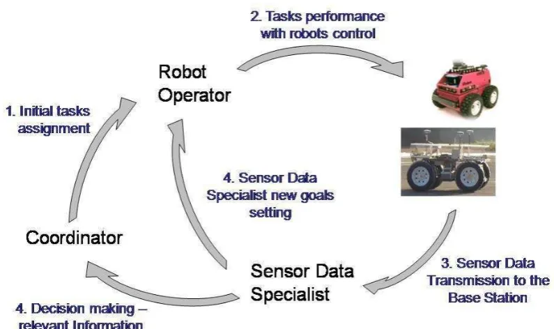
Several categories of base station users, with different operational / analytical skills, have to cooperate during missions.
For that purpose three roles have been identified:
1. Robots Operators (RO) are in charge of teleoperating the robots, through individual robot monitoring and control functions.
2. Sensor Data Specialists (SDS) are in charge of supporting decision making through monitoring of science data (and in particular assessing chemical hazards).
Figure 4 Categories of base station users
Base station, set up and innovation
Literature background
A number of teleoperation interface designs exist in the literature, either explicitly
considering USAR type of applications [Adams-95] [Ricks-04] or addressing teleoperation interface design in more general terms [Peer-08] [Micire-09]. As far as USAR robot interface design is concerned, a commonly agreed issue is the importance of situational awareness (SA) [Endsley-88]. However no consensus exists on the best way to provide users with SA, as stressed by Drury in [Drury-04]]. In addition, according to Olivares [Olivares-03] it is critical that the interface between human and robot be as simple and easy to use as possible. Therefore the challenge in USAR teleoperation interface design is to convey sufficient situational awareness to the user while minimizing the required cognitive load, in a simple to use interface. This is an essential issue which we wanted to address in our work. Another important issue in the interface design process for any concrete application but also in USAR is to repeatedly involve users, as this is the only way to capture final users'
expectations. User Centered Design (UCD) is in particularly relevant when the involved users are actually representatives of the application area for which the interface is designed. Similar to Casper and Murphy [Casper-03] and Adams [Adams-05], we approached end users from the early stage of requirements collection through to end-user evaluation of the consecutive implementations, over a period of almost three years. Firefighters from SyFire (UK) as well as crisis management actors such as those of the DOVO bomb disposal squads (Belgium) strongly supported our efforts.
Actually, a major challenge of our work was to combine the features and specificities of both the View-Finder and Guardians project into a single concept of a robot teleoperation station. The main differences in practice are the number of robots to interact with (from 2-3 robots in View-Finder to up to 30 in Guardians), the presence of human crews on the field, in
e.g. by sending high level commands to groups of robots (e.g. explore an area, escort a firefighter), primarily within an indoor (structured) environment.
User centred HRI design is a common design approach derived from the more general, well known User Centred Design (UCD) philosophy, which basically consists in explicitly
considering end-users needs and expectations along the different steps of the design. UCD in HRI design has been incorporated by designers for more than 15 years [Adams-94] [MacKenzie-98], but has been getting widely spread and adopted in the community only more recently (roughly for the last 5 years). As refinements of, or in addition to the UCD approach, specific design approaches and tools have been introduced in the literature to cope specifically with HRI, such as the Goal Directed Task Analysis (GDTA) [Adams-05] which aims at better understanding how users would make use of the robot interface, or the GOMS method (Goals, Operators, Methods, and Selection Rules, [John-96]) that has also been further refined [Drury-07] for the HRI field.
Alternative approaches to UCD have also been considered for HRI in the research
community: in particular the Ecological Interface Design (EID) approach, that focuses on the work domain and environment rather than on the end user or specific task. This approach to interface design suits applications involving multiple users with multiple perspectives in complex systems (has been tested and applied in process control for power plants [Vicente-90], aviation [Burns-04], medicine, etc). It has been further proposed as a paradigm for
mobile robotics teleoperation (introduced as ―Ecological Display‖) by Ricks, Nielsen and
Goodrich in [Ricks-04] and [Nielsen-07], from which our work takes some inspiration. Although the design approach we adopted is essentially based on UCD, we attempted to incorporate in our approach some of the recipes and methods of EID, as a complementary approach. We believe that EID is a promising HRI design approach, especially in
applications where a number of agents (i.e. multiple users, multiple robots) shall interact altogether. However according to us it is not possible to develop a successful HRI design without the involvement of users in the process. As a consequence, introducing a
methodology that would unify, merge the assets, or comply both with UCD and EID
paradigms is an interesting and certainly rewarding direction that we started investigating in View-Finder.
Base station set up and innovation
As a baseline principle, we decided to promote touch screen interaction methods. In
particular, it is foreseen that most of the operator‘s time will be dedicated to monitoring
Figure 5 A demonstration setup for the View-Finder base station.
Figure 5 shows the demonstration setup the base station; it physically consists of (1) a Linux PC running essentially the Base Station Core (BSC), a Mission Data Recorder and
Dispatcher (MDRD) and the interfaces to the different robots and other sub-systems (i.e. CMIS), and (2) several Windows PCs running the HMI clients for the different end users.
The HMI display inspiration comes from Ecological Interface Design (EID), as explained earlier. The most noticeable way we applied Ecological Display recipes is through e.g. limiting the amount of potential eye catching points or areas in the GUI (and in particular the amount of gauges), and making as obvious as possible the status and characteristics of the robots in their environment, with a main area of the GUI representing in a synthetic way the contextually relevant robot information. The main operator‘s GUI is depicted in Figure 5. Several areas can be identified:
(1) The main visualization zone, filling the largest screen space. It provides with an overall, immediate understanding of the global situation. Robots are represented in their (known) environment.
(2) Viewport navigation: it allows the user controlling different parameters of the main view, including zoom, rotation, camera heading (in 3D only), 2D/3D mode and textual
information display.
(3) Operator actions area: this area gathers a number of buttons allowing swarm level control of the robots.
(4) Overall map view: it helps understanding where in the overall space is situated the currently observed area. The highlighted area represents the field of view appearing in the area (1).
(5) Mission log: this area displays notifications of essential events, either originating from the base station or from elsewhere in the system, during operations.
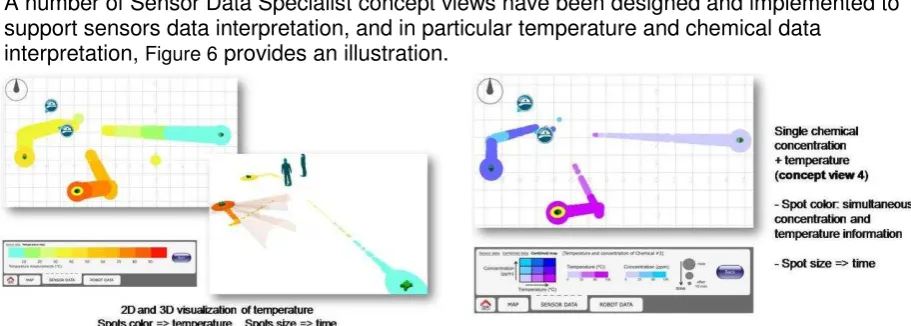
A number of Sensor Data Specialist concept views have been designed and implemented to support sensors data interpretation, and in particular temperature and chemical data
[image:15.595.70.526.470.633.2]interpretation, Figure 6 provides an illustration.
Figure 6, Sensor data specialist view
Three steps in the evaluation process have been carried out:
1. First step was an early protoype end-user test trial to gather qualitative user feedback. 2. Second step was an expert evaluation.
3. Third step was a formal end user usability evaluation session.
Evaluation criteria have been formulated, focusing on different aspects of the usability
aspects of the user interface. They are based on Scholtz‘ six evaluation guidelines [Scholtz -02]. Effectiveness, efficiency and user satisfaction metrics have been used in the evaluation process. Results from the successive usability evaluations confirmed a number of our design choices and helped fixing most shortcomings. In terms effectiveness, efficiency and user satisfaction, results looked promising. Additional usability evaluation sessions (in particular with a multi-users setup) are planned as a follow-up of View-Finder base station design and development efforts.
For the incident coordinator a Prototype Mission Planning, Scheduling and Execution
Monitoring (MPSEM) component has been developed and integrated into the base station. A View-Finder specific task planning domain has been implemented, relying on the
Hierarchical Task Planning (HTN) based planning engine Shop2 (open source, from the University of Maryland [Nau-03], [SHOP2-09]). It allows breaking down high level tasks into elementary actions (typically motion or perception oriented), taking into account available resources and time. It is able to call for specialized planners providing (e.g. path planning or perception planning capabilities) during planning, relying on the latest available world
representation (e.g. environment Digital Elevation Map, robots and sensors health, status, availability) as well as mission constraints (area scope / limitation, available time, etc). Its full connection and use in the View-Finder system relies on a task plan execution module: this however requires means to be aware of the execution status of requested tasks on-board the robots, which could unfortunately not be implemented on the View-Finder robotics platforms within the timeframe of the project. Therefore the MPSEM in View-Finder is
considered a proof-of-concept, which will be further developed and consolidated internally as a follow-up of View-Finder research effort.
Further reading
F. Warlet, C. Pinzon, W. Mees (RMA), J. Gancet, E. Motard, and M. Ilzkovitz (SAS), Crisis management supporting architecture in View-Finder. in IARP/EURON RISE'2009, 12-14 Jan 2009, Brussels, Belgium
G. Chliveros, and L. Alboul (SHU), An algorithm and Architecture for 3D vision dat fusion. in IARP/EURON RISE'2009, 12-14 Jan 2009, Brussels, Belgium
Danny Weston (SHU): Could machines be responsible for a major disaster? IARP WS
RISE‘2010, Sheffield Hallam University, 20-21 Jan 2010
Jeremi Gancet, Elvina Motard, Miguel Muñoz Arancón, Lynn de Proft, Kim Vijle and Michel Ilzkovitz (SAS): Remote HRI for Crisis Management Support in the View-Finder Project, IARP
WS RISE‘2010, Sheffield Hallam University, 20-21 Jan 2010
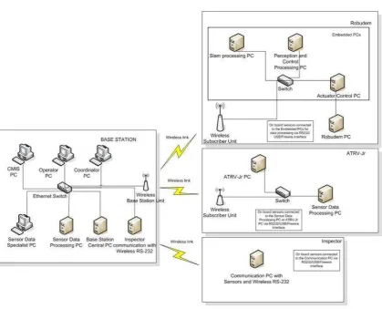
Communication Network
In ViewFinder a distinction is made between intra-platform and inter-platform
Figure 7 Overview of the communication network
Figure 7 provides an overview of the communication network. The types of data are:
Telemetry data, status messages, laser scan data originating from the sensors which are passed on from the sensors processing components to the robots, and from the robots to the Base Station
Emergency, control and navigation commands data from the Base Station to the Robots
Video stream from the Robot to the Base Station
The wired communication inside each main actor (Base Station and Robots) ensures enough bandwidth and delivery guarantees. However, these aspects become critical in the communication between Base Station and Robots. The bandwidth of a wireless link
dependents on many factors, for instance the distance and visibility between end points. This causes communication problems like higher loss probabilities, as well as increased and non-deterministic latency. Delays and unpredictable latency affect the smoothness of the video transmission. However, high latency and losses cannot be accepted for some critical commands sent from the Base Station to the Robots, for example a stop command is very critical. Moreover, data collected by sensors such as map plots, should be able to reach the Base Station in a timely manner in order to be used appropriately. As a consequence, traffic prioritization and QoS management for different flows is needed in order to ensure that each type of data in the communication can be treated according to the requirements, i.e.:
emergency commands must be handled with the higher priority and the minimum latency;
video streams could be handled with lower priority with respect to other data types, but ensuring a low jitter (latency variance).
The latency problem can be solved by adding intelligence on the robot. For interactive robot control (tele-operation), 100 msec latency is acceptable; between most other human
interfaces at the base station and robot, 1 sec is acceptable.
The other key issue is the bandwidth that will be required for sending sensor data from the robot to the base station. The management of the bandwidth is performed by Mailman, which is a high performance message bus offering Quality of Service for wireless networks. It comprises a network level transport protocol specification and implementation. The main features of Mailman are its facilities for controlling datagram priorities, allocating fair shares of bandwidth to all users, controlling congestion and sending notifications to clients, allowing user programs to easily address each other, providing automatic discovery of servers and support for reliable and non reliable datagram delivery.
A related aspect is the interconnection between different components. This is managed by two middleware platforms: CoRoBA and Player, refer to the section Robot Platforms and Middleware below.
Further reading
U.Delprato, M.Cristaldi, G.Tusa, (IES), Italy: A light-weight communication protocol for tele-operated Robots in risky emergency operations, Handbook ‗Emerging sensor and Robotics Technologies for Risky Interventions and Humanitarian de-mining (a book series on Mobile Service Robotics published by Woodhead Publishing Company-UK ) in current edition,
Chemical Sensors
The possible presence of hazardous materials is a considerable risk factor. The ViewFinder project dedicated considerable work to the development of a sensor array for the detection of volatile organic chemicals (VOCs) in low and pre-explosive concentrations as well as for olfactory robotic navigation. Two types of chemical sensors are used to detect low
concentration and high concentration of VOCs and toxic gases. A QCM (quartz crystal microbalance) sensor array was built utilising quartz crystals spun-coated with thin films of different amphiphilic calixarene molecules to provide a base for pattern recognition of different volatile organic chemicals (VOCs). Commercial Metal-oxide semiconductor (MOS) sensors were also used in the same array for the benefit of dedicating low dedicating low concentration.
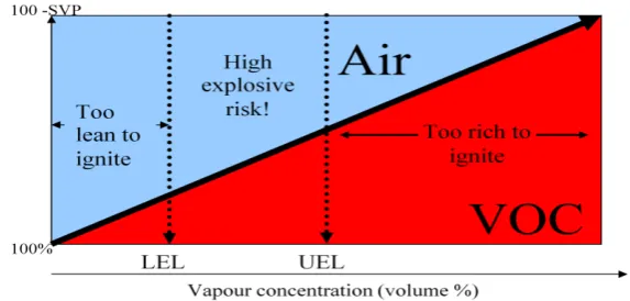
Figure 8, Flammable properties of a typical organic solvent
Table 1 shows the LEL and UEL for selective VOCs where LEL and UEL determine levels which are out of vapour saturation for each individual VOC. The concentration detected by the two types of sensors is in 'parts per million' (ppm) values. The chemical sensors are working within their sensitivity limitations. The MOS devices are very sensitive, i.e. up to 500 ppm, and the coated QCMs sensitivity is sufficient for concentrations above 500 ppm; with the latter being VOC category dependent.
[image:19.595.148.451.389.518.2]The aim of using these two types of chemical sensors in this project is to detect the high concentration of VOCs within the area of LEL-UEL and upper than UEL in the explosive region as shown in figure 1 and 2.
Table 1
Chemical (VOC)
LEL UEL
(%) ppm (%) ppm
Hexane 1.1 1845.5459 7.5 12583.268
Ethanol 3.3 2932.215 19 16882.45
Acetone 2.5 5921.54 12.8 30318.285
Propane 2.2 434.247 13.7 2704.1745
Toluene 1 286.20775 7 2003.4542
Table 1, LEL and UEL for some selective VOCs
Figure 9 illustrates the LEL-High explosive UEL-risk range for each of the VOCs is considered in table 1. The data shown in this figure is for less than 20% of the vapour saturation limit for any of VOCs, which indicates an environment hazardous, filled with less than 20% of the fully engulfed area.
MOS devices' limitation of 500 ppm is used for an earlier indication and alarming of gas leakage and to be taken as an urgent duty of fire fighter to solve the coming hazardous problem before the concentration is increased and pass to the high explosive risk range. In the case where leakage is out of control and concentration is increased, the fire fighters have to deal with the case as of high risk situation.
If concentration is higher than 500 ppm, the QCM sensor takes place in the sensing process to recognise the analyte and identify the concentration of such analyte.
Hexane. The space between curves and curves diversity provides a good basis for the recognition code of the analytes. The ANN was built to detect this diversity and identify the VOC.
Figure 9 LEL and UEL for five different types of analytes.
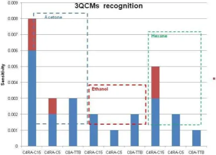
The sensitivity code recognition for Acetone, Ethanol, Propane, Toluene and Hexane were test many times to establish the reproducibility and stability of coated QCM (C4RA-C15, C4RA-C5 and C8A-TTb) for such VOCs. Sensitivity varies considerably as Figure 10 shows.
Figure 10, Sensitivity for Acetone, Ethanol and Hexane
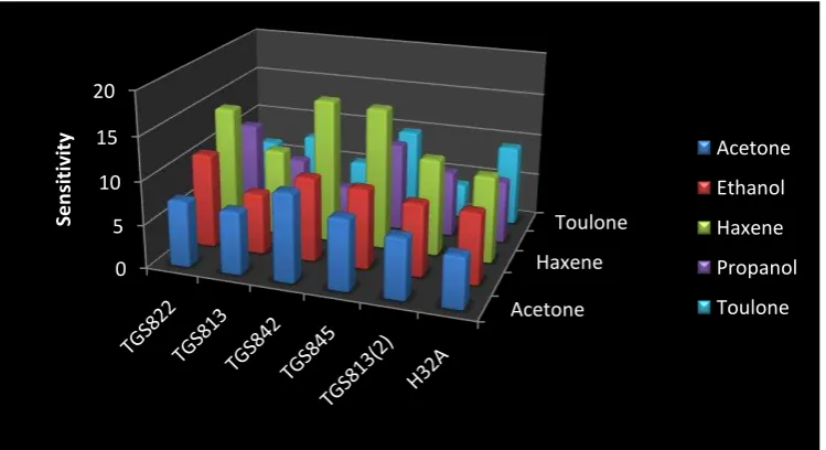
[image:20.595.190.408.443.599.2]Figure 11, Sensitivity of the chosen MOS devices exposed to analytes; Acetone, Ethanol, Hexane, Propane and Toluene.
Further Reading
Alan, Holloway, Real time machine olfaction for mobile robot applications, In Proc. of IARP/EURON Workshop on Robotics for Risky Interventions and Environmental Surveillance, RISE08. Benicàssim (Spain). 2008.
Alan F. Holloway, Alexei Nabok, Abbass A. Hashim, Jacques Penders, The Use of Calixarene Thin Films in the Sensor Array for VOCs Detection and Olfactory Navigation, Sensors & Transducers journal (ISSN 1726-5479), Vol.113, Issue 2, February 2010, pp.71-81.
Map Building and Reconstruction
The ViewFinder robots have the primary aim to gather data and the project addresses key issues related to map building and reconstruction.
For map-building, the consortium has analysed and implemented a range of methods and algorithms. For direct robot navigation the project implemented a 2D SLAM procedure, while the 3D data representations are used for remote inspection and aiding the human operator‘s perception. For the latter purpose two different approaches are implemented. Also a method to reconstruct Structure from Motion has been developed.
Indoor
System Overview
The map building and reconstruction processes consists of three main algorithms: simultaneous localisation and mapping (from now on referred to as SLAM-2D); fusion of point cloud in 3D with camera image (from now on referred to as Fusion-3D); and 3D reconstruction. The first two algorithms, SLAM-2D and Fusion-3D, are placed on the robot on a separate processing unit (WP6-PC) which is connected to the robot's processing unit via an Ethernet cable link. The 3D reconstruction process is placed at the base-station.
Acetone Haxene
Toulone
0 5 10 15 20
S
e
n
si
ti
v
it
y Acetone
Ethanol
Haxene
Propanol
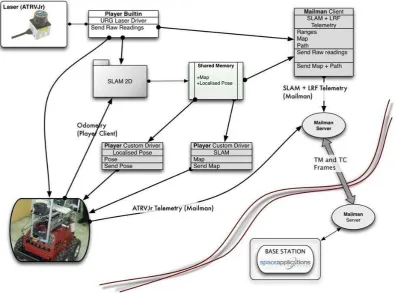
Figure 12, Modules and Processes for 2D Localisation and Map building
The sensor data required for these processes are placed on-board the robot. The robot acts as a Player server the processes act as clients. Communication with the Base-Station is established via Mailman clients as indicated in Figure 12. The SLAM-2D process
communicates to the Base-Station an updated map represented as an occupancy grid, the corrected pose of the robot and the path it has taken to current position. When the 3D acquisition takes place the robot halts and maintains its position, which renders the SLAM-2D process as idle. Thereafter, the Fusion3D process takes place which in turn saves the fused point-cloud in a file that is read and transmitted to the Base Station.
The Base Station accepts streams of data from the WP6-PC processing unit, which includes a constant stream of images, a constant stream of Laser Range Finder data, sporadic fused point-cloud in 3D and corrected odometry data (position and bearing of the robot). The update of a 2D map with the robot path is also sent and depends on the processing time required from the SLAM-2D process. The SLAM-2D process time to updating the map relates to the resolution of the map; i.e. the higher the number of grid cells in the occupancy grid, the more time it takes for the process to update the map. Likewise, the same is true for the Fusion-3D process, which depends on the time required to acquire the point-cloud in 3D. The higher the number of tilt moves the tilt-unit has to make, the more time it takes to
acquire and process the point-cloud. Indicatively, for 10 tilt moves, the point cloud in 3D takes approximately 2 seconds to acquire and process.
Slam-2D
estimating the most likely robot pose; that is either via linear interpolation or via Rao-Blackwell variance reduction. The hypothesis space is of variable size of particle number and the particles' generation is based on multi-variate normal populations. The map
[image:23.595.68.518.169.381.2]representation is that of an occupancy grid in 2D (i.e. a bitmap) with a pre-defined resolution, refer to Figure 13. The latter affects the computational complexity of the process due to longer updating times. A number of data sets have been acquired and the process was tested and validated throughout the various trials.
Figure 13, 2D grid map.
Point cloud / image acquisition
Figure 14 Laser with tilt unit and camera mounted on the robot
The acquisition of point clouds in 3D and image frame for fusing in the scene representation is implemented by means of the Player robotics middleware, using drivers available on the server. An additional driver has been developed to acquire a structured point cloud in 3D; that is to say for every line of laser measurements the tilt increases by small angular steps. The driver takes into account the minimum and maximum angles allowed from the tilt unit and synchronises with the laser range finder in order to provide local (x, y, z) coordinates that correspond to the point cloud in 3D. The existing driver in Player, which provides a `pointcloud' proxy, has an issue with reading these points from a temporary buffer. This issue was corrected. However it was judged that the type of acquisition used by the existing driver provides ambiguous results for the 3D reconstruction process, even though it was observed that it tends to be a faster acquisition method.
Fusing image and point cloud in 3D
Figure 15, The original scene left and the acquired point cloud right
The camera parameters are commonly known as the `camera matrix', describing the internal camera parameters. The points in 3D, (x, y, z) are projected on the image plane (x,y), while assuming a pinhole camera and small distance from camera origin to laser range finder. The projection includes corrections for: distortion on the camera plane coordinates, and an ad-hoc correction for the displacement of the camera origin to that of the laser origin.
The fusion process takes the 3D coordinates of a set of points in space (in local reference frame or camera reference frame) and the intrinsic camera parameters (camera matrix), and returns the pixel projections of the points on the image plane.
Figure 16, Left, wireframe of reconstructed point cloud; right, mesh representation.
Processing of the resulting point cloud in 3D
[image:25.595.85.478.450.648.2]the {x, y, z, R, G, B} vectors are being read the number of points in each planar scan of the Laser Range Finder is known.
Since the number of vertices per line scan is known, e ach vertex can be connected to its counterpart in the next line. Some adjustments with respect to brightness and contrast of the independent colour channels (R, G, B) also takes place while the procedure is running. The adjustments take place depending on the central scan line and for visualisation purposes. Additional features are also added outliers are detected, and `removed'. An example of the result of reconstruction is illustrated in Figure 16.
Outdoor
The Robudem robot used for the outdoor scenario of the View-Finder project relies on vision as its primary sensing modality. Therefore, the amount of information which can be extracted from the measurements acquired by the on-board stereo camera system must be
maximized. To this extent, multiple processing cues for the visual data are established. An important aspect of all these processing cues is that the information they deliver must be available in real-time, or near real-time. This constraint limits the complexity of the applied algorithms and calls for a balanced compromise between the quality of the output and the required processing time.
Spatial reasoning and depth perception play a crucial role in the reasoning process of any intelligent robot. Therefore, it is imperative that the 3D characteristics of the terrain can be extracted by the camera system. Stereo vision is a traditional approach towards achieving depth perception at reasonable framerates. However, the traditional fast stereo techniques still suffer from problems such as incomplete results due to un-textured areas. Other approaches are able to provide dense reconstruction results (which means a real depth value for each image pixel), but these techniques are in general not suited for real-time
processing on ―normal‖ hardware. Therefore, we developed a dense stereo approach which
mixes fast-but-incomplete stereo data with camera motion information and anisotropic diffusion to achieve a dense depth reconstruction at near real-time framerates. Outdoor mobile robots, which have to navigate autonomously in a totally unstructured environment need to auto-determine the suitability of the terrain around them for traversal. Traversability estimation is a challenging problem, as the traversability is a complex function of both the terrain characteristics, such as slopes, vegetation, rocks, etc and the robot mobility characteristics, i.e. locomotion method, wheel properties, etc. Therefore, we
propose an approach where a classification of the terrain in the classes ―traversable‖ and ―obstacle‖ is performed using the proposed dense stereo approach as input data.
Visual Simultaneous Localization and Mapping
The reasoning system is the central unit in an autonomous robot. According to the
environment state, it must allow the robot to localize itself in the environment and to seek for free paths. To accomplish these two tasks, it bases it reasoning on a model or a description of the environment. In our application, for a robust localization, the robot integrates data from a set of sensors: vision camera, Global Positioning System (GPS), Inertial Navigation
A well known vision-based approach is the MonoSLAM algorithm of Davison et al. This is a real-time SLAM approach for indoors in room-size domains, which recover the 3D trajectory of a monocular camera, moving rapidly through an unknown scene. Davison's algorithm is not suitable in larger environments. To be able to use the monoSLAM algorithm in large areas, in this project we propose to build several size limited local maps and combine them into a global map using an 'history memory' which accumulates sensory evidence over time to identify places with a stochastic model of the correlation between map features. In our implementation, the dynamic model of the camera takes into account that the camera is on the top of a mobile robot which moves on a perfect ground-plane at all times and the SIFT feature detector is used instead of Shi and Thomasi algorithm. The SIFT features are proved to remain stable to affine distortions, change of viewpoint, noise and change in illumination. Using SIFT features allows also a more reliable feature matching by using the advantage of the space-scale invariance parameters of the SIFT features.
Dense 3D Reconstruction
When confronted with a large crisis, the crisis management teams require a global overview of the crisis scene. In practical situations, however, it is near impossible to obtain such a global overview, due to the abundance of information coming from different sources and the lack of a global model of the crisis scene where all this information can be nicely visualized upon. In this section, we propose an automated 3D reconstruction approach for building a global 3D model. This 3D reconstruction approach is based on dense structure from motion (SFM) recovery from images captured by a camera on-board a semi-autonomous crisis management robot. Dense structure from motion algorithms aim at estimating a 3D location for all image pixels.
To address the classical dense structure from motion shortcomings, we adopt a dual approach for dense structure estimation. The approach combines the strength of the more robust feature-based structure from motion approaches with the spatial coherence of dense reconstruction algorithms. Dense reconstruction is regarded as a high-dimensional data fusion problem with as inputs the camera motion parameters and 3D coordinates of feature points estimated by sparse reconstruction and dense optical flow. The base constraint of the variational approach is the traditional image brightness constraint, but parameterized for the depth using the 2-view geometry. This estimation of the geometry, as expressed by the fundamental matrix, is automatically updated at each iteration of the solver. A regularization term is added to ensure good reconstruction results in image regions where the data term lacks information. An automatically updated regularization term ensures an optimal balance between the data term and the regularization term at each iteration step. A semi-implicit numerical scheme was set up to solve the dense reconstruction problem. The solver goes out from am initialization process which fuses optical flow data and sparse feature point matches.
The developed methodology is capable of estimating a high quality 3D reconstruction of a natural scene, which makes it a valuable tool for human crisis management teams. Indeed, the results obtained during a real crisis management exercise, show that the visual models outputted by the presented method, can increase the situational awareness of the human crisis managers by integrating localized information on the 3D model.
Stereo vision
Development of novel stereo vision algorithms suitable for robotic applications. The
developed algorithms focus on low computational complexity, real-time execution and quality dense resulting depth maps. Sophisticated methods have been employed and further
algorithm, which performs a 2D correspondence search using a hierarchical search pattern. The intermediate results are refined by 3D Cellular Automata (CA). The disparity value is then defined using the distance of the matching position. Therefore, the developed algorithm can process uncalibrated, non-rectified stereo image pairs, maintaining the computational load within reasonable levels.
Problems occurring in robotic vision applications due to realistic, non-ideal lighting conditions have been examined and suitable algorithmic solutions have been developed. Many robotic and machine-vision applications rely on the accurate results of stereo correspondence algorithms. However, difficult environmental conditions, such as differentiations in illumination depending on the viewpoint, heavily affect the stereo algorithms' performance. An algorithm has been proposed that uses a new illumination-invariant dissimilarity measure in order to substitute the established intensity-based ones. The new measure can be adopted by almost any of the existing stereo algorithms,
enhancing it with its robust features.
Also, problems in image quality arousing due to robot‘s locomotion have been investigated
and active stabilization solutions have been provided. These problems occur due to the rough outdoor terrain, where the robot used in the View-Finder project have to operate. Furthermore, the resulting implementations of the developed stereo vision algorithms have been used for terrain traversability analysis and obstacle avoidance applications, in
cooperation with RMA for the outdoor scenario of the project. Vision-based obstacle avoidance algorithm for autonomous mobile robots have been developed. The developed algorithm uses a minimum of sensors and avoids, as much as possible, computationally complex processes. The only sensor required is a stereo camera. The developed algorithm consists of two building blocks. The first one is a stereo algorithm, able to provide reliable depth maps of the scenery in frame rates suitable for a robot to move autonomously. The second building block is a decision-making algorithm that analyzes the depth maps and deduces the most appropriate direction for the robot to avoid any existing obstacles.
Victim detection
A primordial task for the fire and rescue services is to assess whether there are still human victims on the incident site. An automated victim detector installed on a semi-autonomous mobile robot is thus of great use to human crisis management teams. Therefore, a vision-based human victim detector was developed. In the scope of this research project, the detection of human body shapes from visual input data was chosen as a recognition method. We have presented an approach, based upon the Viola-Jones (face) detector, which was adapted, such that human victims lying on the ground can be detected. The vision-based human victim detector makes it possible to raise an alarm for a remote operator when a victim is detected. The remote operator can then determine whether the classification was correct and take the appropriate actions. As such, an incident site can be scanned for victims semi-autonomously by a mobile robot, relieving the already stressed human crisis managers from the tedious and dangerous task of searching for victims.
Further Reading
A. Amanatiadis, A. Gasteratos, S. Papadakis and V. Kaburlasos, Image Stabilization in Active Robot Vision, Robot Vision, ISBN 978-953-7619-X-X., IN-TECH publishing.
L. Nalpantidis, A. Amanatiadis, G. Sirakoulis and A. Gasteratos, An Efficient Hierarchical Matching Algorithm for Processing Uncalibrated Stereo Vision Images and its Hardware Architecture, Submitted for publication in IET Image Processing
L. Nalpantidis and A. Gasteratos, Biologically and Psychophysically Inspired Adaptive Support Weights Algorithm for Stereo Correspondence, Submitted for publication in Robotics and Autonomous Systems, Elsevier.
L. Nalpantidis, D. Chrysostomou, and A. Gasteratos, Obtaining Reliable Depth Maps for Robotic Applications with a Quad-camera System, Second International Conference on Intelligent Robotics and Applications, (ICIRA 2009), 16 - 18 December 2009, Singapore. L. Nalpantidis, I. Kostavelis, and A. Gasteratos, Stereovision-based Algorithm for Obstacle
Avoidance, Second International Conference on Intelligent Robotics and Applications, (ICIRA 2009), 16 - 18 December 2009, Singapore.
Y. Baudoin, D. Doroftei, G. De Cubber, S.A. Berrabah, C. Pinzon, F. Warlet, J. Gancet, E. Motard, M. Ilzkovitz, L. Nalpantidis, and A. Gasteratos, View-Finder: Robotics Assistance to Fire-Fighting Services and Crisis Management, IEEE International Workshop on Safety, Security, and Rescue Robotics, (SSRR 2009), 3 – 6 November 2009, Denver, Colorado, USA.
Kostavelis, L. Nalpantidis, and A. Gasteratos, Real-Time Algorithm for Obstacle Avoidance, Third Panhellenic Scientific Student Conference on Informatics, (EYPHKA 2009), 10 – 12 September 2009, Corfu, Greece.
L. Nalpantidis, A. Amanatiadis, G. Sirakoulis, N. Kyriakoulis, and A. Gasteratos, Dense Disparity Estimation Using a Hierarchical Matching Technique from Uncalibrated Stereo Vision, IEEE International Workshop on Imaging Systems and Techniques, (IST 2009), pp. 427-431, 11 - 12 May 2009, Shenzhen, China.
Geert De Cubber, Daniela Doroftei, Sid Ahmed Berrabah, Hichem Sahli: Combining Dense structure from Motion and Visual SLAM in a Behavior-based Robot Control Architecture, International journal of Advanced Robotics Systems , submitted and accepted (March 2010, Vol 6, n°1 http://sciyo.com/journals/volume/issn/1729-8806/volume/7/number/1)
Janusz Bedkovski, Grzegorz Kowalski, Andrzej Maslowski: Fast GPU-Based Laser Range Finder LMS SICK 200 Simulation using the compute Unified Device Architecture (NVIDIA CUDA), European Journal of Mechanical and Environmental Engineering, Vol 2009-2, p21-23
L. Alboul and G. Chliveros, A System for Reconstruction from Point Clouds in 3D: Simplification and Mesh Representation, Proceedings of the International Conference on Control, Automation, Robotics and Vision (ICARCV 2010), Dec 2010 Singapore.
G. Chliveros and L. Alboul. Building photo-realistic models in robot assisted rescue operations. In SEECCM 2009, 2nd South-East European Conference on Computational Mechanics Image Processing and Visualisation Symposium, 2009
G. Echeverria and L. Alboul, Shape-preserving mesh simplification based on curvature measures from the Polyhedral Gauss Map, International Journal for Computational Vision and Biomechanics, v.1, n. 2, 2008 (edited in 2009)
Sid Ahmed Berrabah (RMA, Belgium), Y.Baudoin (RMA, Belgium): Data Association for Robot Localization in Satellite Images, International Journal of Advanced Robotics ( Vol 6, N°1, March 2010)
S.A. Berrabah, Y. Baudoin: VIEW-FINDER : Robotics Assistance to fire-Fighting services - Robot Localization, International Conference on Robotics, Informatics, Intelligence
control system Technologies (RIIT'09), 11-14 Dec 2009, Bangkok, Thailand
Sid Ahmed Berrabah: GPS Data Correction Using Encoders and INS Sensors, Handbook
‗Emerging sensor and Robotics Technologies for Risky Interventions and Humanitarian de -mining (a book series on Mobile Service Robotics published by Woodhead Publishing Company-UK ) in current edition,
G. De Cubber, D. Doroftei, L. Nalpantidis, G. C. Sirakoulis, and A. Gasteratos, (RMA, DUTH) Stereo-based terrain traversability analysis for robot navigation. in IARP/EURON RISE'2009, 12-14 Jan 2009, Brussels, Belgium
S.A. Berrabah, GPS data correction using encoders and INS sensors. in IARP/EURON RISE'2009, 12-14 Jan 2009, Brussels, Belgium
G. De Cubber, and G. Marton (RMA), Human Victim Detection. in IARP/EURON RISE'2009, 12-14 Jan 2009, Brussels, Belgium
Sid-Ahmed Berrabah, Y.Baudoin (RMA) : Simultaneous Localization and Mapping in
Geo-referenced Images, IARP WS RISE‘2010, Sheffield Hallam University, 21-22 Jan 2010 Geert De Cubber: On-line and Off-line 3D Reconstruction for Crisis Management
Applications, IARP WS RISE‘2010, Sheffield Hallam University, 21-22 Jan 2010 Ioannis Kostavelis, Lazaros Nalpantidis and Antonios Gasteratos (DUTH): Comparative
Presentation of Real-Time Obstacle Avoidance Algorithms Using Solely Stereo Vision, IARP
Georgios Chliveros, Lyuba Alboul, Fusing LRF data and Images, IARP WS RISE‘2010, Sheffield Hallam University, 20-21 Jan 2010
Janusz Bedkowski (PIAP): Augmented reality approach to robotics, IARP WS RISE‘2010, Sheffield Hallam University, 20-21 Jan 2010
L. Nalpantidis and A. Gasteratos, Stereo Vision for Robotic Applications in the Presence of Non-ideal Lighting Conditions, Submitted and accepted for publication in Image and Vision Computing, Elsevier, 2010
Robot Platforms and Middleware
Software Architecture
The new software architecture of ATRVJr mobile robot where developed during 3rd year of V-F project by the PIAP research team[2][3]. The main achievement is the compatibility between several communication techniques such as Corba/CoRoBa, Player/Stage,
Mailman. It was done by usage Corba as the core for the architecture. The main advantage of the proposed approach is that the architecture supports several communication models such as client – server (peer to peer), producer – consumer, mixed: client/server –
server/client. Thus it is possible to implement complex control software with flexible communication scheme.
The comparison between Player, Corba and Mailman was performed during several robot trials with different software configurations. It is important to emphasize, that the architecture allows to define different configurations, that can be executed immediately.
Player characteristic:
The Player middleware provides almost complete set of needed hardware drivers, therefore it is very useful middleware that improves mobile robot development. The limitation is the client-server communication protocol between the components. For this reason we are forced to request the server each time we would like to have updated information. Therefore, the local LAN of the mobile robot can potentially become overloaded by the data exchanges between the components. Another disadvantage is related to the video acquisition,
compression and sending via wireless network. We observed that Player was not robust enough to send video in satisfied time (10 fps), and sometimes the communication was fully lost with no clear reason.
Corba characteristic:
The Corba middleware provides several communication models (client – server, producer – consumer, mixed: client/server – server/client) that is useful for developing a flexible software architecture of the mobile robot. The main difference between client - server and producer - consumer is related to the separation between consumer and producer done by the Event Channel. This solves the problem with handling the exceptions during data exchange. It is important to realize that event (producer - consumer) is more robust than
request (client - server) in real – time applications, essentially because of the prioritization . Mailman characteristic:
Mailman was designed for data exchange between 2 subnets via a wireless communication channel with low bandwidth. The prioritization mechanism allows to design real time
Several experiments where performed for Player/Corba/Mailman comparison. The important observation is that Player provides robust hardware drivers for the off-the-shelf ATRVJr mobile robot. Unfortunately the system based only on Player can not meet the V-F
requirements. The video from existing hardware can not be send in real time. The additional components based on Corba such as VideoCorbaServer and HighLevelController improved the software architecture, therefore it satisfies the V-F requirements. The VideoCorbaServer with built-in compression method provides a video stream that can be visualized (real time) by a CorbaClient installed on the PC located in Base Station. The HighLevelController receives the control data from the BaseStation and executes it via Player components. The architecture based on the Player/Corba components fully satisfy the V-F requirements, where additional Corba components solve the problems related to the well known Player disadvantages. The improvement based on the replacement of Corba for wireless communication by Mailman boosts the performance of data exchange, because of two reasons: usage of the UDP protocol and prioritization. The main advantage of the usage of the Mailman is the possibility of the fast system reboot (the service discovery method in Mailman is faster in the comparison to service discovery method in Corba).
The main achievement is the knowledge how to combine the existing techniques to improve the robotic system with the reduction of the effort needed to reinvent existing solutions.
Robot Navigation
The project is targeted towards data gathering and information sharing between robot and the base station from the point of view of navigation the robot should assure special
functionality, i.e., it should accept and perform at least two commands ―go to goal‖ and ―explore region‖.
To accomplish first we have chosen A* search algorithm as a basis in our implementation of path planner. The choice was motivated by the effectiveness of the algorithm. We adopted it to use in the urban environments smoothing the path and assuring robot will choose a safe path. In addition to high level A* based path planning and to satisfy the second requirement i.e. obstacle avoidance a new algorithm was implemented. It bases on the set of rules, taken from the real-life experiments. The parameters and rules were adjusted by expert during the process of tuning of this algorithm. The algorithm performs well given input of mounted sensing devices i.e. sonars and Hokuyo URG-04LX laser.
The second functionality ―explore region‖ uses the first command as the mean to perform the
task. We assume a region to explore as a circle. The algorithm steps are as follows: robot
receives the command ―explore region‖ with the input (P, r), where P is a middle point (x,y) of
the circle in the global map and r, which is the radius of the circle. Next, based on the radius length target goals are chosen. Robot follows the list of generated points stopping in each place and performing the scan of the environment. The behavior of robot in the
intermediates points can be adjusted to perform more sophisticated actions.
The novelty of Our approach lays in the separation of two layers behavioral layer (based on reactions) and planning layer on the single PC based computer using prioritization.
Therefore the path planning which can take considerable amount of processor time cannot interfere basis behaviors of robot putting the robot on the obstacle.
Behavior-based Robot Control
The control architecture describes the strategy to combine the three main capabilities of an intelligent mobile agent: sensing, reasoning and actuation. These three capabilities have to be integrated in a coherent framework in order for the mobile agent to perform a certain task adequately. To combine the advantages of purely reactive and planner-based approaches, research was performed to implement a behavior-based controller for autonomous
navigation. The performance of the behavior-based controller depends on the
problem include the weight optimization and the goal programming method. In earlier work, we proposed a method to choose the weights based upon a reliability measure associated to each behavior. The principle behind the calculation of the activity levels is that the output of a behavior should be stable over time in order to trust it. Therefore, the degree of relevance or activity is calculated by observing the history of the output of each behavior. Solving the action selection problem using reliability analysis has the big advantage of incorporating direct information from the system under control into the control process. On the other hand, this architecture does not offer a human decision maker the ability to interact with the
decision process. In ViewFinder, the autonomous agents have to interact with humans on the field, exchanging knowledge and learning from each other, this is a serious shortcoming.
Common techniques for taking into account a decision maker‘s preferences take do this by offering a human operator the ability to input some objectives or ideal points. These
approaches, however, suffer from the disadvantage that no reliability data from the sensing and other processes is taken into account while performing action selection. Therefore, we have developed a novel technique of solving the behavior fusion or action selection problem by integrating the classical goal-programming method with a new approach based on
reliability analysis. The experimental validation of the presented technique was performed by doing field tests, evaluating the performance of all subsystems and of the robotic system as a whole. As for the globally integrated result, it can be concluded that the robot has become a semi-autonomous agent: it can handle a high-level task (searching for human victims) with minimal input from human operators, by navigating in a complex, dynamic and environment, while avoiding potentially hazardous obstacles.
Further Reading
Eric Colon (RMA) : The unmanned Ground Vehicle Centre (UGVC) working to improve military capability (visual 3D perception, Simultaneous Localisation and Mapping, Partnerschips within International Projects, Resaearch into Multi robot Systems, Military Robotics 2009 (www.militaryrobotics.co.uk 18-19 May 2009
Y.Baudoin, D.Doroftei, G.De Cubber, S.A..Berrabah, C.Pinzon, J.Penders,A.Maslowski, J.Bedkowski: VIEW-FINDER : Outdoor Robotics Assistance to Fire-Fighting services,
International Symposium Clawar‘2009 – Istanbul, October 2009, 9-11
Y. Baudoin, D. Doroftei, G. De Cubber, S.A.Berrabah, E. Colon, C. Pinzon,(RMA), A.Maslowski, J.Bedkowski (PIAP): View-Finder: a European project aiming the Robotics assistance to Fire-fighting services and Crisis Management, IARP workshop on Service Robotics and Nanorobotics, Beijing, 28-29 Oct 2009
Geert De Cubber, Daniela Doroftei: Human Victim Detection and Stereo-based Terrain Traversability Analysis for Behavior-Based Robot Navigation, Handbook ‗Emerging sensor and Robotics Technologies for Risky Interventions and Humanitarian de-mining (a book series on Mobile Service Robotics published by Woodhead Publishing Company-UK ) in current edition,
Janusz Bedkowski, Andrzej Maslowski, PIAP, Poland: NVIDIA CUDA Application in the Cognitive Supervision and Control of the Multi robot System Methodology for the supervision and control of the multi robotic system with CUDA application, Handbook ‗Emerging sensor and Robotics Technologies for Risky Interventions and Humanitarian de-mining (a book series on Mobile Service Robotics published by Woodhead Publishing Company-UK ) in current edition,
P. Kowalski, J. Bedkowski, and A. Maslowski, ‗PIAP) Implementation of the Indoor
Autonomous Navigation for ViewFinder Project. in IARP/EURON RISE'2009, 12-14 Jan 2009, Brussels, Belgium
K. Verbiest, and E. Colon (RMA), Cooperative multi-robot path planning. in IARP/EURON RISE'2009, 12-14 Jan 2009, Brussels, Belgium
J. Bedkowski, and A. Maslowski (PIAP), NVIDIA CUDA Application in the Cognitive
Supervision and Control of the Multi Robot System. in IARP/EURON RISE'2009, 12-14 Jan 2009, Brussels, Belgium
S.A. Berrabah, and C. G. Rozmarin (RMA), Robot Navigation Based on Adaptive Fuzzy Controller. in IARP/EURON RISE'2009, 12-14 Jan 2009, Brussels, Belgium
J. Bedkowski, P. Kowalski, G. Kowalski, A. Maslowski (PIAP), and E. Colon (RMA),
Improvement of ATRV Jr Software Architexture for ViewFinder Application. in IARP/EURON RISE'2009, 12-14 Jan 2009, Brussels, Belgium
D.Doroftei, G. De Cubber, E. Colon, and Y. Baudoin (RMA), Behavior Based Control for An Outdoor Crisis Management Robot. in IARP/EURON RISE'2009, 12-14 Jan 2009, Brussels, Belgium
Janusz Bedkowski (PIAP): ViewFinder, Mobile robot platform for fire fighting assistance, IARP
WS RISE‘2010, Sheffield Hallam University, 20-21 Jan 2010
Kristel Verbiest, Eric Colon (RMA): Securing Hostile Terrain with a Robot Team, IARP WS
RISE‘2010, Sheffield Hallam University, 20-21 Jan 2010
Daniela Doroftei, Eric Colon (RMA) : Decentralized Multi-Robot Coordination for Risky Interventions, IARP WS RISE‘2010, Sheffield Hallam University, 20-21 Jan 2010
Direct human Robot Interaction
In rescue operations the (semi) autonomous robots may encounter human beings. In combination with the Guardians project, the ViewFinder project developed a human robot interface for 'in-the-field' interaction.
Conceptual Design
The governing concern in the design process was to ensure that the robot behaviours and human robot interaction represented a minimal additional mental and/or communication load for fire fighters. Based on this, the conceptual model of the fire fighter being treated as an exceptional member was developed. The exceptional features being the predominance of the fire fighter in terms of autonomy, skill and authority. In terms of interaction, this meant that the robots will in effect surround the fire fighter and move with them.
In cases where the robots identify hazards or specific safe routes they provide information for the fire fighter to employ and act on at their discretion. This conceptual model of HRI for group of robots poses a number of questions about how to inform the fire fighters about potential hazards and potential safe routes to follow in highly oppressive and stressful situations.
In formulating the problem the fire fighters were consulted and shown likely or possible configurations using a simple display desktop based prototype. The prototype simply
illustrated possibilities and also animated the intended robot operations through a number of animated storyboards (in PowerPoint). Through this consultation a peripheral visual display was chosen as the most appropriate means of helping direct fire fighters.
Figure 17 First prototype of the peripheral visual display
The robots determine a direction that fire fighter has to follow by taking into account: the fire fighter position, the position of possible obstacles that have to be avoided and the
destination position. Based on this information and the fire fighters pose the direction to be taken is calculated and visually illustrated to fire fighter.
The prototype shown in Figure 17 was tried with professional fire fighters. The findings from the first trial were somewhat of a surprise. The analogical interface appears in principle to be simplistic and intuitive and thus easily adopted. However, this was not the case. The clear