Tangible Pods
A raw tangible user interface (TUI) for
audio and haptic feedback
Bachelor Assignment for Rawshaping Technology
Peter Schaefer • February 2015
Tangible Pods: a raw tangible user interface (TUI) for
audio and haptic feedback
Peter Schaefer
s1355155
March 1st, 2016
University of Twente
Industrial Design
Faculty of Engineering
Summary
This Bachelor Assignment (BA) is a contribution for the development of tangible interfaces that support multi-sensory perception, metacognition and physical manipulation. The assignment is to explore, experiment and test diverse ways of creating tangible user-interfaces (TUI) that support visual, tactile and auditory interaction and afford audiovisual feedback and assistive responses (i.e. cues, nudges). Furthermore, part of the assignment was a study on the impact of interaction modalities on embodied cognitive processes. A user-centered design approach was applied in combination with a bottom up iterative design process and a prototyping phase. Iterations were made based on a vision and requirements for an interaction that supports the user by allowing him/her to use his/her hands for 3-D physical manipulation to create sounds in a playful and synthesized way. The vision and requirements are based on earlier work from the Free Assignment (FA) and research done about the theory behind Rawshaping Technology (RST), other related work and embodied cognition.
Samenvatting
Deze bachelor opdracht (BO) is een bijdrage aan de ontwikkeling van haptische ‘user interfaces’ die gebruik maken van multi-sensorische perceptie, metacognitie en fysieke manipulatie. De opdracht is het exploreren, testen en experimenteren met diverse vormen van ‘tangible user interfaces’ (TUIs) die visuele, haptische en auditieve interacties ondersteunen en audiovisueel en ondersteunend feedback (b.v. ‘nudges’) genereren. Daarnaast wordt als deel van de opdracht een studie uitgevoerd over de invloed van interactie modaliteiten op ‘embodied cognitive processes’. Een op de gebruiker gefocuste ontwerp-aanpak is toegepast in combinatie met een ‘bottom-up’ iteratief ontwerpproces. De iteraties zijn gebaseerd op een visie voor een nieuwe soort interactie die de gebruiker ondersteund door drie-dimensionele, fysieke interactie met de handen om te zetten naar audiovisueel feedback. De visie is gebaseerd op eerder werk van de Vrije Opdracht (VO) en onderzoek over de theoretische achtergrond van Rawshaping Technology (RST), ander gerelateerd werk en theorie over ‘embodied cognition’. Bovendien zijn er eisen, wensen en specificaties opgesteld gebaseerd op dit onderzoek.
Preface
With this assignment I got the opportunity to do exactly what I wanted to do, therefore it is really dear to my heart. During my bachelor in Industrial Design Engineering I have come to be more and more weary of designing products and found more excitement in creative applications of interactive technology, especially when they are used for making music. During the Free Assignment a new world of possibilities opened up for me and I learned about the many things that have been done by professionals and hobbyists. This inspired me to learn how to do the same and expand my vocabulary as a designer by learning how to use these technologies. This assignment was also the longest, most detailed and most difficult design process I have gone through so far.
Assignment
The objective of this assignment is to explore, experiment and test diverse ways of creating tangible user-interfaces (TUI) that support visual, tactile and auditory interaction and afford feedback (i.e. cues, nudges) and assistive responses. Also part of the assignment was a study on the impact of interaction modalities on embodied cognitive processes. The aim is to design a hybrid design tool (HDT) for interacting within a virtual environment VE and to study the cognitive impaired (e.g. autism, cognitive impaired, developmental disorders) in support of meta-cognitive skillfulness and deficiencies.
Facing the challenge of having to design something from the ground up that has to work and live up to my vision has given brought me more experience.
List of abbreviations
2-D = two dimensional 3-D = three dimensional AAS = Active Acoustic Sensing
ADHD = Attention Deficit Hyperactivity Disorder ASD = Autism Spectrum Disorder
BA = Bachelor Assignment CAD = computer aided design DoF = degree of freedom FA = Free Assignment GUI = graphical user interface Gyro = Gyroscope
HCI = Human-computer interaction HD = high definition
HDT = hybrid design tool IC = integrated circuit
ICT = information and communication technology IDE = integrated development environment IEK = Intuition-Experience-Knowledge IF = interface
IMU = inertial measurement unit IR = infrared
IxD = Interaction Design JUI = jamming user interface
MIDI = Musical Instrument Digital Interface MSS = Malleable Silicone Shape
MUX = multiplexer
NUI = natural user interface
PDD = Pervasive Developmental Disorder Piezo = piezoelectric element
RFID = radio-frequency identification RSFF = Raw Shaping Form Finding RST = Rawshaping Technology
SFCS = Swept Frequency Capacitive Sensing SUS = System Usability Scale
TP = Tangible Pods
TUI = tangible user interface UI = user interface
VE = virtual environment
Table of contents
Summary
Samenvatting
Preface
Assignment
List of abbreviations
Table of contents
1. Introduction
3. Ideation and conceptualization
1. Kinetic sand interface
2. The Rawshaping approach
3. Tangible Bits
4. Jamming user interfaces (JUIs)
5. Natural user interfaces (NUIs)
6. Virtual environments for people with autism spectrum disorder (ASD)
7. Conclusion: requirements, wishes and specifications
1. Vision
2. Iterations
3. Sensors for tangible interaction
4. Concepts
5. Concept choice
1. Structure
2. Tangible Pods
2. Research and development
4
5
6
6
7
8
10
14
26
11
12
15
16
21
21
22
23
25
5. Evaluation
6. Conclusion and future work
7. References
Appendix
4. Testing and prototyping
1. Sensor tests
2. Design decisions
3. Dimensions
4. Making the prototype
5. Arduino software
6. Usability test
1. Music therapy mails
2. Touch sensing
3. Mechanical prototype
4. Arduino code
5. List of springs
6. Prototype cost calculation
7. Usability test questionnaire
8. Usability test results
9. Kinetic sand interface and usability test videos (DVD)
38
60
62
64
70
40
42
46
49
54
56
1. Introduction
1.
Structure
The report for this assignment is structured around its process. First, the analysis of theories and work that influenced the design process is laid out. It starts with describing preceding work done in the Free Assignment. Then the RST approach to Human-computer interaction (HCI) and design processing is explained. This forms the basis for the approach to this assignment. After that, a summary of other work in three related fields of study (TUIs; JUIs and NUIs) is given and the influence on the Tangible Pods concept is explained. Next, a detour into touch sensing that was not further pursued in the design process is briefly described. Finally, to explore interaction for people with autism the role of theory on embodied cognition and music therapy are described.
In the next chapter, the ideation and conceptualisation phase is laid out. It starts with a description of the vision that fueled the process. Then the visualized iterations and the resulting three concepts for the interface are presented. Next, an overview of sensors that can be used for measuring physical interaction is given. After that, the feasibility of some of these concepts were tested with simple test set-ups. Then one concept was chosen and more iterations on the concept were made to explore its possibilities.
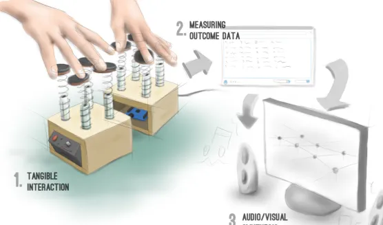
Figure 1.1 Tangible Pods concept
2.Tangible Pods
Tangible Pods is a tangible user interface that consists of multiple “pods” that form a surface and can be physically manipulated/ sculpted to create input data. It is a flexible interface that can be used in a range of applications including music, 2-D and 3-D modeling (see figure 1.1).
The interface is made for instant creation and self-expression through sound and visuals using computer technology. It facilitates this by giving digital data a haptic manifestation. Similar to a computer mouse a physical action measured by a sensor is
WIMP interfaces since the user can rely more on his/her knowledge of interacting with physical objects. Because of this it can facilitate participation of non-experts in e.g. electronic music making.
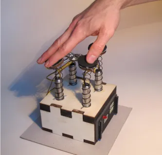
Because I have an interest in electronic music the prototype (see figure 1.3) is an execution of the tangible pods concept that proves the feasibility of applying it as a musical instrument/synthesizer. In the prototype compression springs from steel wire serve as tactile feedback. Together with the soft neoprene fabric of the pressure sensors the springs create a tactile richness. Pressure sensors, piezos and an accelerometer are used to measure the physical input and an arduino microcontroller is used to process the resulting input data which can then be sent to a variety of
music programs (i.e. any that works with MIDI data). The prototype has four pods for practical reasons (see Design decisions), but the number can be changed to better fit the application’s needs. The pods could could for example be embedded in an application that supports physical manipulation with two feet (see figure 1.2).
Figure 1.1 Tangible Pods concept
Figure 1.3 Tangible Pods prototype
user
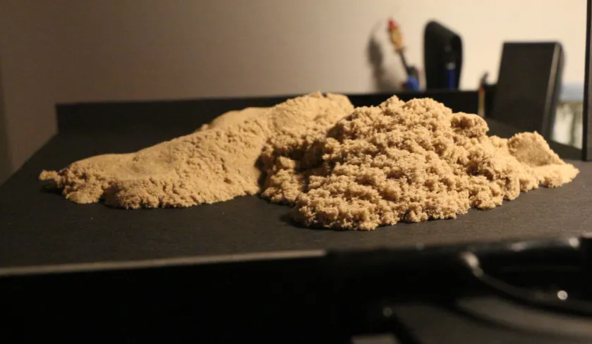
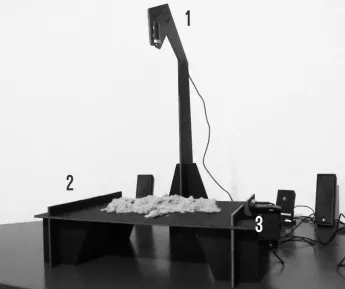
[image:13.595.258.592.434.753.2]Figure 2.1 Kinetic sand
2. Research and
development
1.
Kinetic sand interface
The design of the tangible pods is partly based onearlier work done during the Free Assignment (FA) for RST during my Industrial Design Bachelor at the University of Twente. During the FA, I developed a tool for the creation and manipulation of audio and sonification using kinetic sand (see figure 2.1). The prototype creates a hybrid connection between material and audio. The design is successful on the tangible side as the sand provides a very pleasurable texture as haptic feedback. However, the technology that synthesized the interaction into sounds did not provide the users with a feeling of being in control. The interaction was based on piezoelectric elements and computer vision. The sand was placed on a foam board platform (see figure 2.2|2), where it could be manipulated. The piezos are mounted under the foam board platform and pick up vibration that are caused by the sand being moved across the surface of the platform. The computer that the piezos are attached to determines peaks in the vibration signal and sends a MIDI signal to Ableton Live -a
music production program- which results in a sound. So every time the user touches the sand or moves it a sound is played in varying amplitude depending on the amount of vibration.
Above the platform an HD (2.2|1)webcam is placed, which is used to determine the position (X and Y) on the platform. A second webcam (2.2|3) is placed on the right side of the platform to determine the height (Z) of the manipulated sand. These values are used to control pitch and effects.
Intermezzo
To get a better grasp on what the kinetic sand interface does, please watch a video of a user playing with the sand that can found in appendix 9 (on the attached DVD).
The interaction of the kinetic sand interface is based on the piezos and a computer vision system comprised of the two webcams. Using the piezos worked well and some users found it surprisingly intuitive. The computer vision was more difficult to implement and there were problems with precision, calibration due to inconsistent lighting and differentiating between the sand and the hands of the user.
[image:15.595.245.591.422.711.2]For this assignment the goal was to develop a similar tool but this time using a different interaction technology instead of computer vision.
Figure 2.2 Kinetic sand interface
1
2
2.
The Rawshaping Technology (RST)
approach
Rawshaping Technology (RST) is doing research on the ideation and abstract conceptualization phase of the design process. RST is also developing hybrid design tools that support the visualization of fuzzy notions informed by tacit knowledge and allow the user to reflect on raw ideas. RST aims to foster designers to be creative and explore uncommon ideas they recognize to have potential. According to Kruiper (2015) the raw idea is larger than and different from the understanding of others, that might be reluctant to it [5]. In the following some important concepts that form the basis of the Rawshaping approach are laid out.
Tacit knowing
According to Polanyi (1966) in order to gain knowledge we process our experiences and sensorial input to form comprehensive entities [6]. By combining perceptions with non-perceived information more abstract and complex comprehensive entities are formed. This is how we can recognize a face without being aware of all of its elements. Knowledge gained from learning experiences is harder to express the more complex it becomes. According to Grant (2011) “…tacitness is something personal, an ability or skill to do something or to resolve a problem that is based, in part, on one’s own experiences in learning” [7].
Polanyi (1966) differentiates between proximal and distal tacit knowing [6]. The focus lies on the distal part which is the comprehensive entity, which is comprised of proximal parts of which one is only subsidiarily aware of. The perception of the proximal parts is influenced by the tacit knowledge of the distal part. As an example Polanyi (1966) states that the human body is an instrument that is not perceived as such, so the distal entity of the body is actually included in the proximal and one becomes less aware of it [6]. Just like we perceive the world through our body, we perceive an artifact (digital or physical) we are working on through the tool we are working with. When one becomes proficient at using a tool, like e.g. a bicycle the focus shifts from how one is sitting on and
balancing the bike to staying on path while moving. The same thing happens in a creative process when one is in a state of flow. According to Csikszentmihalyi (1990) [8] flow is a state in-between unselfconscious immersion during performance of a task and reflection-in-action (Schön, 1983) [9] leading to fast choice making. Other forms of reflection informed by tacit knowing in a creative process are reflection-in-conversation, reflection-in-practice (specialization through repetition of actions) and reflection-on-action (after the action was performed) [9].
Usability and hybrid tools
RST, Robertson et al. (2009) [10] and Kosmadoudi et al. (2013) [11] see a deficiency in usability in computer aided design (CAD) systems. Usability in an artifact or system is defined by its affordances and the sequence of actions needed to achieve an affordance. Affordances in Interaction Design (IxD) are what an artifact or system allows its user to do, understand, see, hear, feel or taste. How difficult performing an action with a tool/artifact is perceived to be depends heavily on how familiar the user is with performing the action to achieve a certain thing. No interface is truly intuitive in the sense that the user does not need any knowledge to use an artifact (Spool, 2005) [12]. By interacting with the world around them people learn how to interact with it. When an interaction is built on this tacit knowledge it is perceived to be intuitive [12].
to achive with physical instruments, they have a high threshold in learning curve and do not foster fast, intuitive exploration of raw ideas.
Hybrid: merging physical and virtual representation
Wendrich (2012, 2014) proposes improving on the deficiencies in virtual design tools by combining the beneficial factors of physical and virtual representation [14, 15]. “We need to develop tools that allow the same subtle physical freedom and gestural motions traditional tools and instruments embody. Tools that support intuitive expressiveness, creative flow, rapid prototyping, allow speedy interaction and give sensory feedback” according to Wendrich (2012) [14].
These tools:
• Support skills and capacities in physical manipulation of the users
• Are flexible and provide the user with a wider range in affordances
• Encourage ambiguity and unpredictability
• Allow for rationalization by capturing every step in the creative process
• Allow for continuous reflection on thought and action through challenging between physical and virtual representation
Intuition-Experience-Knowledge (IEK) model
Wendrich (2009, 2010, 2012) proposes a process in which the design problem is approached holistically and intuitively [16, 17, 14]. In this approach the problem consists of multiple intimately interconnected parts that cannot be split up into sub-problems. This holistic approach, which is visualized in figure 2.3, allows the designer to connect existing and tacit knowledge to come up with uncommon, refreshing ideas.
[image:17.595.59.454.549.752.2]The role of the designer is to explore these raw ideas, fuzzy notions and possible solutions through experimentation, externalization and play. During and after the externalization of ideas, the designer rationalizes and reflects on these ideas, which leads to new, richer iterations. McCullough (1996) argues we should learn and explore with our hands, because they are very subtle, sensitive, probing, differentiated and connected to the mind [18].
Through externalization in form the designer accumulates new tacit, personal knowledge about the scale, weight, texture, constraints and form of an artifact, which also informs the iterative process. The design process according to the IEK model is visualized in figure 2.4. Finally, a solution to the design problem can be found through incubation and reflection on the process.
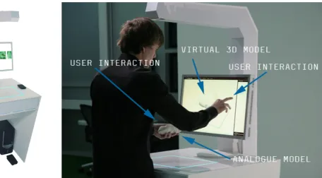
Raw Shaping Form Finding hybrid design tool (RSFF HDT)
[image:19.595.133.590.503.755.2]One of the tools developed by RST that serves as a good example for implementation of the Rawshaping theoretical background is the RSFF HDT (see figures 2.5-6). This tool captures physical objects and displays them as three-dimensional models on a touchscreen (2.6). This allows the user to iterate through two-handed manipulation of a physical, tangible object and then selecting, sorting, choosing and manipulating any of these iterations virtually (see figure 2.7). The interface also allows for collaborative interaction with multiple users on one or more tools.
Implementation
The Tangible Pods interface (TP-IF) was developed for audio and haptic feedback, while RST focused on the development of hybrid tools for visual and haptic visualization, ideation and conceptualization in earlier and ongoing work. Still, parts of the Rawshaping theoretical background were implemented in the concept and final design of the TP-IF. The Tangible Pods prototype supports intuitive experimentation and expression in sound through tangible physical interaction. The interface could also be applied to combine visual and audio feedback, but for this assignment the focus is on synthesizing sound. The interface should allow the user to think in sounds and nudge him/her to explore uncommon sounds by introducing randomness into the process. Furthermore, it should improve on some of the usability deficits of existing music production tools (i.e. Ableton Live and Logic Pro).
The guidelines were used to develop requirements and wishes for the final design (see chapter 2.7).
These guidelines for the development of an intuitive TUI for audio and haptic feedback are derived from earlier work by RST:
The interface should
1. Mediate between physical and virtual representations
2. Support un-tethered two-handed tangible interactions
3. Facilitate tinkering & exploration of sound 4. Facilitate a process of iteration, synthesis and
morphing
5. Allow for immediate interaction
6. Allow for intuitive expressiveness of the user 7. Be intuitively usable and give the user a sense of
being in control
8. Facilitate getting into a state of flow
9. Support thinking processes and decision making in sound production
10. Support collaboration, conversation and back and forth signaling between multiple users using multiple tools
Tangible Bits (Ishii et al., 1997) are digital data that can be accessed through interaction with tangible objects [19]. Ishii et al. (1997) establish three ways of bridging the gap between VE and physical environments:
• Interactive surfaces in an architectural environment that allow immediate access to a VE
• Hybrid artifacts that allow access to and
manipulation of digital data belonging to a physical artifact
3.
Tangible bits
JUIs are malleable and shape changing and perceived to be more organic than traditional interaction modalities, like mouse and keyboard or touchscreens. According to Follmer et al. (2012) there are two types of high-resolution shape sensing methods: Index-matched particles and fluids and capacitive and electric field sensing [21]. Follmer et al. propose the development of interfaces that are not only deformable and stay in form but can also be computationally actuated to change their material properties like stiffness [21]. They see that so far there have been more advances in shape sensing and mechanical actuation than in particle jamming, which is the computational actuation of material properties. An example for a JUI is Tunable Clay [21], which uses a hydraulic system to change the material properties and structured light depth sensing to measure deformation of the interface.
In contrast to JUIs, other interfaces that allow for haptic feedback provide information for the user by changing their shape. Haptic feedback can be categorized into active and passive forms of feedback. Passive feedback is the feedback a material provides because of its properties, for example; foams, springs and rubbers return to their original if deformed to a certain degree. Active feedback, or actuation, is when an active mechanism changes the form of an interface. In mechanical actuation this is often done using
4.
Jamming user interfaces (JUIs)
electrical motors. An example for an interface that uses mechanical actuation is Ros’s (2015) ‘Stewart’, which is a tactile interface based on the Stewart platform [22]. The platform can move with six degrees of freedom (DoF), using six servomotors. It can also be used for haptic input, allowing for tactile communication between the user and the machine.
Mechanical actuation and particle jamming provide new ways of giving feedback to users, which have been neglected in traditional UIs. Even though in many buttons springs are used to provide passive haptic feedback, the full potential of passive feedback modalities have not been explored in traditional UIs. Furthermore, passive feedback is easier to implement in interfaces, because no motors or pumps are needed. Because of this, a choice was made to explore passive feedback modalities for the development of Tangible Pods.
• Ambient media such as sound, light and temperature that influence and are influenced by users
5.
Natural user interfaces (NUIs)
According to Jetter et al. (2014) computers still demand special skills from users and distract them with secondary tasks, like configuration of settings [23]. Instead they should offer immediate access to affordances “so that we are freed to use them without thinking and “mental gymnastics” and to focus beyond computers on new goals”[23; p. 1140]. Jetter et al. draw on the concept of conceptual integration to explain why computers can be very difficult to use. Conceptual integration is the idea that humans learn complex concepts like ‘shame’ or ‘happiness’ through integration of other less complex concepts. This means that basic concepts that can be learned through perception like ‘up’ and ‘down’ are connected to complex concepts through many steps of integration (Lakoff et al., 1980) [24]. This relates to theory on tacit knowledge, because one is mostly unconsciously using these concepts to carry out tasks. This also means that the mind has to be viewed as inherently embodied, because even the most abstract tasks are built on bodily experiences.
Jetter et al. state that computers are difficult to use because they require too many steps of conceptual integration and do not make enough use of simple concepts that most people have learned through interaction with the physical world and their social context [23].
If WIMP interfaces are difficult to use, because they are too abstract, complex and ‘unnatural’, how can we design VEs that are perceived to be natural? When interaction with a VE is closer to interaction in the ‘real’ world, it becomes easier for users to understand and use digital technologies. Valli (2006) also sees the necessity of hybrid interaction tools and virtual representation of artifacts that can be manipulated similarly to physical artifacts. He proposes the development of VEs that support natural interaction [25]. “Natural interaction is defined in terms of experience: people naturally communicate through gestures, expressions, movements, and discover the world by looking around and manipulating physical stuff”(Valli, 2006) [25;
p. 1]. The key aspect of Valli’s vision is to achieve spontaneous interaction through simplicity and physical interaction. According to him immediacy in interaction can be achieved by making representation of content, organization of information and the interactive device more and more simple and invisible [25]. As interactive technologies become embedded in and behave like the physical world users become less aware of the mediation taking place and the interaction becomes more natural.
6.
Virtual environments for people with
autism spectrum disorder (ASD)
The choice to study people with ASD in relation to novel computer interfaces was made based on the belief that the assumed average user of UIs does not exist and studying people that do not fit the norm could possibly enrich the design process and help developing interfaces that adapt to the user’s needs instead of the other way around. Rajendran (2013) argues that researching the relationship between people with autism and information and communication technology (ICT), is important for three reasons [26]:
• It can say a lot about affinities and aversions of people with autism
• ICT offers many opportunities to intervene, support and facilitate skill development in people with autism
• It can give new insights into human-computer interaction in general
The affinities and aversions of people with autism also make this field of research very challenging, as they vary greatly between individuals. To this day we have no full understanding of the disorder and according to Happé et al. (2006) it is probably impossible to explain it with one theory [27]. There is however consensus that ASD is a pervasive developmental disorder (PDD) and theories on certain aspects of the disorder exist [28, 29, 30].
The purpose of this analysis is not to give a complete overview on theories on ASD, but to establish a basic understanding of autism and to develop guidelines to help with the development of a TUI in support of cognitive deficiencies associated with ASD.
A Brief description of autism
The ASDs are sometimes categorized into three types of autism, which are all PDDs: autism per se, Asperger syndrome and PDDs that are not otherwise specified [26]. However, recently some (Lord et al., 2012) abolished this categorization, instead differentiating in severity of the disorder [31]. According to the
American Psychological Association (APA; 2013) symptoms of autism include persistent difficulties with social interaction and communication in different environments and repetitive behavioral patterns resulting in difficulties in social life or occupation [32]. These symptoms begin, but are not necessarily recognizable, in the early developmental phase [32].
Embodied cognition and autism
Rajendran defines autism as a “disorder of social cognition, of cognition, of emotion, of perception and of movement” [26; p. 335]. All of these aspects also play a role in human-computer interaction. Addressing all of them in the design of a TUI would be impossible within the time constraints of this assignment. Instead, a choice was made to focus on embodied cognition and how the body’s physicality influences psychological processes.
According to Antle (2009) there has been a shift from viewing cognition as a disembodied processing of signals to a process that requires physical and mental activity [33]. Antle says this shift to embodied cognition is one that should be taken into consideration in human computer interaction (HCI) especially the following three ideas in embodied cognition [33]:
• Meaning is created through spatial restructuring of elements in a (virtual) environment
• Physical actions can enhance and simplify cognitive tasks, e.g. physical manipulation can help learning the manipulation of mental models
• Bodily experiences can provide metaphors to help understanding abstract concepts, e.g. physical movement as a metaphor for progression in development (“look, how far I’ve come!” [33, p. 29])
[33]. This is similar to Wendrich’s (2012) proposal for hybrid tools that merge the beneficial factors of physical and virtual tools [14]. Two examples for interfaces that implement object manipulation are the RSFF HDT through manipulation of the object itself and the tangible programming space (Fernaeus et al., 2006) [34], which allows users to solve programming problems by changing the spatial location of objects. Mental tasks can be simplified when physical interaction with a tangible is used as input [33], like in the example of the RSFF HDT.
Antle et al. (2009) developed a hybrid physical VE that maps full-body input actions to musical sounds [35]. In the development they found that tracing abstract cognitive processes from related bodily movements and using this for the mapping process improved the experience and performance of users. This suggests that more abstract thinking processes can partly be traced back from physical movements.
Music therapy for people with autism
The developed interface supports physical input and audio and haptic feedback, which makes it a musical instrument. Music therapy is often applied with people with autism. It is often applied to train sensory perceptions and expressing emotions in different ways. To better understand how musical instruments can be used in music therapy for people with autism I asked two people working with children with autism (see appendix: music therapy mails) to give their perspective. They contributed the following ideas that influenced the design of the interface:
• The learning threshold should be very low, like e.g. that of Lego-toys
• When playing with children with autism it works best to observe what the child is doing and to then join and copy the child in order to make a connection
• Catering to the child’s interests, skills and context is important
• Setting goals for the child to have moments of success, can be very motivating
• Skills that therapists aim to support include expression of emotions, ideas and perceptions, building self-assurance, discovering one’s own identity, social interaction and communication • Music can support expression of emotions especially
when the person has difficulties communicating with (body) language
• Children have individually different needs and react differently to music therapy
These ideas are by no means representative. They do however give a perspective on the context the interface might be used in. The ideas influenced the design process to a varying degree. Some influenced the concept directly, others were not directly taken into account. For example the assumption that there is a need for low-threshold tools that support a playful interaction and musical expression of emotions was reinforced. Furthermore, the idea that the interface should offer a wide range of affordances through simple but distinct sequences of action was supported. In the case of musical instruments this could mean allowing for a wide variety of sounds to be played through simple physical actions. Additionally, requiring only one action at the same time, while allowing for combination of actions keeps the learning-threshold low, while offering challenges for the users to achieve. The ideas also highlight the importance of communication and collaboration through music using one or more instruments. This means the interface needs to support use of at least two people at the same time and/or back- and forth- signaling between multiple users with multiple devices.
7.
Conclusion: Requirements wishes and
specifications
The literature research is summarized in a list of require-ments, wishes and specifications, which were used to develop the vision that fueled the creation of iterations and concepts. The requirements are more essential to developing a concept that lives up to the vision than the wishes. The specifications informed decisions about the technical realization of the concept.
Requirements: The interface
• Allows for manipulation of tangible material as an input modality
• Provides haptic and audio/visual feedback • Mediates between physical and virtual
representa-tions
• Allows for simple, immediate interaction • Allows for intuitive expressiveness of the user • Facilitates tinkering, exploration, iteration and
synthesis
• Is intuitively usable for people with and without a cognitive disability
• Fosters abstract thinking processes through tangible interaction
Wishes: The interface
• Has a low learning-threshold and challenges more advanced users
• Offers a wide range of affordances
• Supports un-tethered two-handed tangible interac-tions
• Facilitates getting into a state of flow
• Supports collaboration, conversation and back and forth signaling between multiple users using multi-ple tools
• Supports ambiguity and randomness • Supports play and enjoyment
• Supports decision making in sound production • Gives the user a sense of being in control
Specifications: The interface
• Achieves tangible interaction without using com-puter vision
Figure 3.1 Role of the user
1.
Vision
Central to this assignment is the interaction the user has with the interface. The interface is designed to allow for a natural, fluid interaction that supports haptic perception and manipulation. According to Jetter et al. (2014) [23] interaction with a digital environment is perceived as natural when the user can apply familiar concepts from interacting with his/her natural environment. With technology becoming increasingly ubiquitous, this so-called natural environment is already a hybrid one, but Valli (2006) [25] argues that knowledge about interacting with and discovering the physical world is something that should be applicable to digital devices. So in order to be perceived as more intuitive the interface should allow the user to spontaneously synthesize digital audio(-visual) data based on affect and intent by physically interacting with a tangible object.
The electronic artist Ash Koosha (2015) [36] describes his process as follows: “I stretch them [samples] like objects to see what’s happening, which opens up a whole other world of sound”. The interface is based on this notion of manipulating sound like objects. That way disembodied (synthesized or sampled) sounds can be played by physically interacting with the interface, reestablishing a (different) link between sound and material. Valli goes so far to argue that in order to be intuitive a digital artifact must behave almost exactly like the physical object it represents, however this approach is limiting to the possibilities (copying, reversing, etc.) of such a natural interface [25]. Difference in behavior of physical and digital artifacts might be counter-intuitive but will always exist with current technology. The resulting hybrid interface can still facilitate discovery, when the physical interaction is familiar but results in something unexpected. The role that the user can take using the different functionalities of the interface is visualized in figure 4.1. The interface should facilitate exploration of possibilties in digital sound synthesis through physical interaction. During synthesis the user should be able to arrange sounds into a composition (by e.g. looping them) and manipulate sound properties (e.g. timbre, amplitude, length, pitch). After that, the user should also be able to reflect on and change the composition and quality of the sound either through
physical interaction or a simple button or screen-based interface. In contrast to gestural interfaces like Kinect [37], exoskeleton interfaces as e.g. developed by Jo et al. (2013) [38] and BodyCI like Myo [39], the aim is not to synthesize data directly from the movement of the body or muscle activity but to synthesize data from the interaction of the body with tangible material. The interface facilitates interaction with computers that is more fluid and natural, but also less precise. The output data has to be interpreted by a computer and translated into sound in a meaningful way. The interface can produce a diverse range of sounds from varying contexts and with varying intensity, pitch, duration and timbre. The data acquired by the sensors could be used for visual (2-D/3-D) interaction as well and be implemented in design processing. The interface gives the user access to possibilities of the digital realm, which are otherwise only accessible by learning software that is developed for professionals and therefore often has a high threshold in learning curve.
Figure 3.2 shows an associative map that was made to create a rough overview of the different aspects of the assignment. It was created using Phrasa*. The map was used to reflect on knowledge and associations regarding the development of a TUI for audio and haptic feedback and the aims behind it. In it, different ideas are visualized and related to each other. Colors were added to make the grouping of ideas visible. One of the things the maps shows are different ideas for interactions with tangibles that could be used in a computer interface (3.2|4). Moreover, first ideas on technologies that could make hybrid tangible interaction possible are documented in the map (3.2|5). The aspect of sound is placed in the center of the map (3.2|3) to show the focus on audio as an affordance. The map also shows that the required capacities (3.2|2) to use the interface are closely related to the user’s experience and what he/she can practice when using the interface (3.2|1).
1
Figure 3.2 Associative map
4
5
2.
Iterations
1
With the users, context and the vision of making sound tangible and graspable in mind, ideas were sketched and visualized to explore how the interface could work, look, feel and interacted with. One requirement was that it would not work with computer vision, because that technique proofed to be difficult to execute in the Free Assignment. When trying to implement computer vision for two-handed interaction the software needs to be able to tell the user’s hands apart from the thing he is interacting with. Using kinetic sand as an interaction modality worked really well, because people want to touch it and it has a pleasant texture.
Figure 3.3 Overview of the iterations
2
3.
Sensors for tangible interaction
To work out how the concepts can be realized, an overview ofsensors that can be used for tangible interaction was made (see table 3.1). There are other possible technological solutions, but these were considered because they are relatively inexpensive, available and information on how to implement them is relatively easy to find. Computer vision was not considered for the technological solutions for reasons stated in the previous chapter (see chapter 2.1). The overview includes information on what the sensor does, what its advantages and disadvantages are and what tangible interactions it can be used to sense. The Arduino platform [40] was chosen to read outputs from the sensors. It is open source, easy enough to learn within the time constraint for the assignment and hardware is relatively inexpensive.
Table 3.1 Sensors for tangible interaction
Sensor What it does Pros Cons Possible application in tangible interaction
Infrared (IR) sensor
Emits IR light and detects IR that is reflected by objects close by. Proximity can be determined using triangulation
Variety of reflectivity only has a small influence on proximity sensing
Relatively short range, only detects object in line of sight
Moving,
approaching an object
Ultrasonic sensor
Measures how long it takes for emitted ultrasonic waves to travel to be reflected back to the sensor
Very precise, not influenced by visual characteristics of object, low-power
Only detects object
in line of sight Moving, approach-ing an object
Load cell
Applying a pressure to the cell changes its resistance. The resulting change in resistance needs to be amplified using a wheatstone bridge
Low-cost Tilt, step on an object
Capacitive sensor (see appendix 2) Touching, approaching an object
Radio-frequency identification (RFID) chip and sensor
Detects electromag-netic fields emitted by a RFID tag
Tag can contain electronically stored data, does not have to be in line of sight
Some tags need power source, objects need to be tagged, 3-D loca-tion tracking still in development (Ko, 2010) [41]
Sensor What it does Pros Cons Possible application in tangible interaction
Flex sensor
Bending it increases resistance of the sensor, which leads to a lower output voltage
Only works in two
directions Twisting, bending a malleable object
Piezoelectric ele-ment (piezo)
Senses forces and small vibrations in material: when a force is applied it creates a propor-tional voltage
Low-cost
Tapping, kicking, hitting an object (and sensing how an object is touched in combination with vibration speaker)
Tilt sensor
Based on a ball in-side the sensor that connects two pins when held upright, only detects if sen-sor is tilted in rela-tion to the direcrela-tion of gravity
Inexpensive
Does not detect amount of tilt or in what direction it is tilted
Tilting an object
Accelerometer Senses static (gravity) and dynamic (motion) acceleration, can measure orientation in relation to gravity
Tilting, moving, shaking, throwing of an object
Gyroscope (gyro) Measures angular velocity
Does not provide enough information to determine orienta-tion
Rotating an object
Inertial measure-ment unit (IMU)
Combines data from accelerometers and gyros determine orientation position and velocity more precisely
Up to six degrees of freedom (DOF)
Tilting, moving, shaking rotating, throwing of an object
Force resistive capacitor
When pressure is applied resistance
decreases Not very accurate
Squeezing, poking, pushing, stepping on an object
Photocell
Resistance decreases with increasing light shining on the resistor
Low-cost, small,
low-power Not very accurate (50%+ variation)
4.
Concepts
In this section the three concepts are described and pos-sible technological solutions to realize these concepts are presented.
Concept 1: Malleable Silicone Shapes
The Malleable Silicone Shapes (MSS) are controllers that can be touched, squeezed, morphed, and pinched. They are equipped with a microphone that records sounds from its surrounding like voices or claps (see figure 3.4). These sounds can then be sampled, manipulated and looped with the interface. Through physical manipula-tion of the shape the user can manipulate and play with the recorded sounds and (re-)discover familiar sounds. The physical manipulation changes the pitch and quality of the sound using effects like reverb, filters, etc. Sounds are played by squeezing or pinching the controller (see figure 3.5).
The MSS contain an Arduino microcontroller that is connected to a piezo that senses squeezing and pinch-ing and four flex sensors that sense whether the shape is bent and on which side bending occurs. The MSS could also have pre-recorded sounds to play with. Furthermore LEDs could be added for visual feedback (in transparent silicone). An accelerometer or IMU could also be added to the MSS to measure e.g. rotation and acceleration.
Sensor Grid
The Sensor Grid (see figure 3.6) is a different version of the MSS. It is a three-dimensional round grid made from steel wire that has flex sensors and piezos attached to it and behaves like a really soft spring. It has a covering layer of silicone on it but is hollow from the inside. The hollow inside is connected to the air outside with a small hole. The advantage of this version over the MSS is that the hollow inside allows for more deforma-tion when it is being squeezed, but it is also harder to make such a shape with a silicone mold.
Figure 3.4 Live sampling
Figure 3.5 Tangible sound
Figure 3.6 Sensor grid
user
L
grid
flex sensor
malleable
shape
user r
Figure 3.5 Tangible sound
user r
Concept 2: Kinetic Structures
The Kinetic Structure is a long rod that has arms attached to it like a tree with branches (see figure 3.7). These arms are arranged in crosses perpendicular to the rod. The crosses arms are connected to the rod with a hinge, which allows them to rotate around the rod. The inner rod also has rotary hinges and can be formed. The arms could be connected to each other with pull springs, causing the structure to go back to its original form after being manipulated.
Each arm contains a gyroscope to measure its rotation. Sudden rotation gets translated into a sound with a certain pitch and angular velocity is mapped to the velocity of the sound. That way subtle manipulation results in subtle sounds and fast sudden manipulation results in louder (more abrasive) sounds.
Figure 3.7 Kinetic structure
user R
Inner rod
Flexible surface
arms
Concept 3: Tangible Pods
The Tangible Pods (TPs) are spherical-like shapes placed on top of flexible steel wire (see figure 3.8). They create a different note when they are tapped or pinched. The pods are placed on a platform that contains a microcontroller that processes the signals from the sensors. They can also be pressed down and tilted to the side, which changes the sound quality and pitch of the note. Tapping and pinching is detected using a piezo and the amount of pressure is detected with a flex sensor. The flex sensors are attached to the steel wire and bend when they are being pressed down. An accelerometer in each pod measures the orientation.
The user can also switch between the loop and the normal mode. When the user activates the loop mode, it (periodically) loop sounds that the user makes and give the user the ability to add to and take away from this loop.
Figures 3.8 Tangible Pods
pods
Button interface
5.
Final concept
Figure 4.1 Prototype
Figure 4.3 Pods
1.
Sensor tests
The goal of these test set-ups was to quickly determine whether the Tangible Pods concept could work using piezos and flex sensors.
Sensor test 1 (version 1 & 2)
The first sensor test (see figure 4.4) consisted of a rapid model that is made up of steel wires glued vertically to a foam plate. Horizontal wires connect the tops of these vertical wires. At the intersections, the wires are connected with play dough. Because the play dough is not strong enough to hold the wire together when they are being moved, it is replaced by foam balls in the second version (see figure 4.5).
In version two the foam balls are glued to the wires. The only sensor in this test set-up is one piezo connected to an amplifier. The piezo is attached to the foam plate and detects vibration in any of the four wires. The signal from the piezo is fed into a computer for analysis. Every time the signal peaks this creates a sound. Peaks are determined by setting a threshold. The value of the
peak determines the velocity (loudness) of the played note. The peak analysis is done in Max for Live [42]with two existing ‘patchers’ (Max for Live programs) called PEAKS and NOTES (Raz, 2013) [43] and sounds are triggered in Ableton Live (see figure 4.6).
Sensor test 2
The second sensor test (see figure 4.7) is similar to the first in that the parts are rapidly put together. There are only two ‘pods’, each consisting of two steel wires with a piezo and foam plates on top. The pods are not connected to each other so that they can move independently. The pods are glued to and standing on a foam plate on top of a steel plate, which provides weight and stability (see platform in figure 4.7). One of the steel wires has a flex sensor attached to it.
All the sensors are paired with an appropriate resistor and connected to an Arduino Uno. Piezos and flex sensors have a varying resistance so the appropriate resistor needs to be approximately equal to the
maximum resistance of the sensor. The resistor acts as a benchmark to how the resistance in the sensor is changing. The circuit looks as follows: 5 V (input voltage) -> resistor -> piezo/flex sensor -> ground. The analog pin is connected in between the resistor and the sensor. The piezo has a maximum resistance of about 1 MOhm and the flex sensor of 10 kOhm.
In this test the peaks in the signal of the piezo are determined with a program written in the Arduino Software (IDE). Every detected peak creates a MIDI note with a certain velocity depending on the value of the peak. These notes are sent to Ableton life using the Hairless MIDI to Serial Bridge. The value from the flex sensor is also converted into MIDI data and sent via a different channel to Ableton Live using the same bridge. The value can then be mapped to any value in Live. This test established the feasibility of the basic working principle for the prototype. The set-up is however too fragile and not a close enough approximation of the concept to be used for further testing.
Detour: Touch sensing
There was also a plan to incorporate acoustic touch sensing into the interface. Active Acoustic Sensing (AAS) is a technique to measure how an object is being touched (e.g. on which side) using a piezo and a vibration speaker. This was not further pursued for two reasons: using this technique requires know-how in the field of data acquisition and measuring three-dimensional physical manipulation is a more important part of the concept and should be pursued instead. More information about AAS can be found in appendix 2.
Figure 4.7 Sensor test 2
[image:41.595.297.591.285.757.2]Figure 4.8 Prototype parts
2
Platforms
3
Compression
springs
4
steel
shafts
6
wooden
box
5
button
interface
1
pods
7
usb cable
2.
Design decisions
The concept was further developed into a working prototype (see figures 4.1 to 4.3 and 4.8.). For this, a couple of design decisions about the dimensions of the prototype and the materials and tools for making it were made that are explained in the following. These decisions are informed by a preceding mechanical version of the prototype (see figure 4.9). For this early version of the prototype only the mechanical function was realized without the electronics. It was decided that a new version had to be made for reasons stated in appendix 3.
Springs
The steel wires that were used in the test set-ups are replaced by compression springs (4.8|3) in the prototype. They are better suited for being physically manipulated by the user, creating input-data (tilting, compression measured by sensors) and giving haptic feedback by going back to their original state. Furthermore, springs are available in a wide range of elasticity and sizes, which makes them suitable for applications of various scale and types of interaction. For example the concept of the tangible pods could then be scaled up to a size where one pod has to be moved with the whole hand or scaled down to a size where it could be put onto furniture and one could still sit or lie on it. To be used for a prototype, the springs had to be in a manageable size and quantity. Also they needed to be elastic enough so that multiple springs would be easily compressible with one hand. Three springs with different lengths, diameters and wire thicknesses were tested (see appendix: list of springs).
The spring that was chosen for the prototype is most suited because it is relatively easy to compress four of them at the same time due to the relatively thin wire thickness and it does not bend to the side as easily as the longer springs. It has a length of 100 mm, a diameter of 17,5 mm and a wire thickness of 1 mm.
Sensors
The sensors are a defining factor in the user experience as they translate analog input into digital data. Many different kinds of sensors have been used for tangible
interfaces (see overview: Technology for tangible matter). Four piezos and pressure sensors and one accelerometer are being used in the prototype. The piezos pick up vibrations in the object they are attached to and were also used in the kinetic sand interface in the Free Assignment. In the prototype for this assignment they are used for detecting peaks in the vibration of the pods, to detect when the pod is being moved. Doing this with piezos is cheap and relatively easy to do, but not very precise. They can also pick up the frequencies of the vibrations, which can be used to determine where and how an object is being touched (see example), but this requires skills in data acquisition and analysis that goes beyond the scope of this assignment.
In addition to the piezos, pressure sensors are being used in the prototype instead of the flex sensors in the test set-ups. Pressure and flex sensors work in a very similar way. When pressed/flexed the output Voltage of the sensor is higher, because the resistance is lowered (Vout = Vin * (R2 / (R1 + R2 ))). Pressure sensors were used instead of flex because they can be implemented in the same way, so that when a pod is being pushed down, the it is being pushed down the higher the output value of the sensor is. The pressure sensors could be better integrated into the design, because they fit onto the round platforms (5.8|2), while the flex sensors do not fit into the inner diameter of the springs when they are bent. The pressure sensors are also hand-made instead of pre-fabricated, to make the prototype as cheap (see ap-pendix: prototype cost calculation) as possible and also because size and material (neoprene) can then be chosen to fit the purpose.
Pods
Different arrangements and numbers of pods (4.8|1) were sketched and tested using just the compression springs. To make up an imagined surface that the user can place his palm on at least three pods are needed. The prices were calculated for all the parts for the different numbers of pods. Choosing four as the number of pods for the prototype was a good compromise in possible interaction versus price.
Wooden box
The pods were placed on a wooden box (4.8|6) that contains the Arduino and the electronic circuit. It is made from multiplex-plate, because that material makes it relatively light but not so light that it easily falls over. The plates for the box were laser cut with teeth at the connecting ends of the wooden plates, which made it easy to neatly glue them together with wood glue. The top plate is thicker than the others because this creates more surface for gluing the steel shafts into the holes in the plate.
Steel shafts
The steal shafts (4.8|4) are there to hold the springs in place and keep them from bending too much to the side. They are a little less then half the length of the springs to still give them enough freedom of movement. The steel shafts are hollow in the middle so that the cables from the sensors can be neatly run through the middle of the springs into the wooden box. The steel shafts have a small hole running through the shaft perpendicular to their long axis. These are placed just above the base of the spring so that the spring gets locked when a split pen is pushed through that hole, holding the spring between the pen and the box.
Button interface
The button interface (see figure 4.8|5 and 4.11) was added to the prototype to allow users to record and repeat sounds as described in the Tangible pods concept (chapter 4.4). The design of the button interface is based on the Ableton Live audio effect Looper (see figure 4.10). Looper can be used to record sounds into a loop that is periodically played back. The interface features three pushbuttons (4.11|2) and one LED (4.11|1). The buttons allow the user to access the functions of Looper. Every time a button is pressed the Arduino sends a MIDI note to Ableton Live that is mapped to a specific function of the Looper effect. The buttons were chosen as an interface modality, because they allow for very precise interaction with only two possible states (pressed and not pressed). To integrate the buttons into the prototype they are placed in a foam board panel (4.11|3) that can be inserted in one of the open sides of the wooden box.
[image:44.595.221.592.410.752.2]When the user presses the ‘record loop’-button all the sounds he/she makes are being recorded into the loop. The red LED indicates whether the loop-function is enabled (red light means function is enabled). Pressing the ‘record-loop’-button again turns off the loop-function. The other two buttons can be used to erase sounds from the loop. The ‘undo’-button erases the last recording, starting from when the ‘record-loop’-button was pressed. The ‘erase’-‘record-loop’-button erases all the sounds in the loop. Originally, there were supposed to be two other buttons, one that doubles the length of the loop and one that makes the loop half as long. These two buttons were scrapped form the design to make it simpler. It was assumed that these two buttons would be confusing to users, as the interface does not display the length of the loop. To display the length of the sample or add additional functionality like erasing and manipulating specific sounds in the loop would have required a different technical solution. Another desired functionality that was not realized is the recording of
sounds from the surrounding with a microphone and playing them back in a manipulated way. This was not possible due to the limitations of working with MIDI in Ableton Live. Live only allows for instruments that work either based on MIDI or audio signals. Adding more functionality would have required writing a program in Max/MSP or the Arduino IDE that works on its own without a digital audio workstation like Live. This would have required too much time and it would also mean that the interface could not give access to the wide variety of sounds that can be made in such an audio workstation.
Figure 4.10 Looper
Figure 4.11 Button interface
1 LED
2 Buttons
[image:45.595.53.527.405.753.2]3.
Dimensions
Part number
Sub-assembly Part name Quantity Material DImension
1
Pod
Wooden disk 4 Multiplex wood 6 mm thick
2 Steel disk 4 Steel plate 0,5 mm thick
P1 Compression spring 4 Spring steel 1 mm wire thickness
P2 Bolt 4 M4
P3 Nut 4 M4
3
Box
Steel shaft 4 Steel tube 15 mm outer diameter
4 Top panel 1 Multiplex wood 18 mm thick
5 Side panel 2 Multiplex wood 9 mm thick
6 Bottom panel 1 Multiplex wood 6 mm thick
P4 Pods and box Split pin 4 1,8 mm diam-eter
7
Button inter-face
Buttons front
panel 1 foam board 5 mm thick
[image:46.595.70.543.374.751.2]8 Buttons side panel 2 foam board 5 mm thick
Table 4.1 Pods, box and button interface parts
Ø 18,5 (4x) Ø 13 (4x)
Ø 15 (4x)
130
11 4 26
10 (4x)
36 (4x)
130
Ø 4 (4x)
Ø 5 (4x)
9
18
Ø 2 (4x)
74
6
ASSEMBLY PODS AND BOX SCALE 3:4 DIMENSIONS IN MILLIMETERS
1
2
P1
3
4
5
6
45 (4x)
Figur
e 4.12
Ass
em
bly
dim
en
sio
na
l dr
aw
ing
[image:47.595.115.488.35.779.2]6 (3x)
110
5 (3x)
6
32
6 (3x)
50
2
24
BUTTON INTERFACE SCALE 1:1 DIMENSIONS IN MILLIMETERS
Figure 4.13 Button interface dimensional drawing
[image:48.595.74.539.74.513.2]4.
Making the prototype
In the following the process of making the prototype is described as well as the reasons for choosing certain production methods.Mechanical parts
The four walls of the wooden box are laser-cut from multiplex sheets of different thicknesses and then glued together overnight using wood glue. Using the laser cutting technique it is relatively easy to cut teeth-like notches into the wooden walls. The teeth make it easier to line up the walls to form a square (looking from the side) and increase contact surface allow for a connection with the glue. The holes in the box that the steel shafts are glued in are also laser-cut.
The shaft that were glued into the holes in de wooden box with epoxy glue are made from a steel tube. The steel
[image:49.595.55.527.378.751.2]tube already had the desired outer and inner diameter and only had to be cut to the right length and rounded off at the top. The rounding was done by hand with a sanding machine. There is also a small hole in each of the shafts for the split pens to go through. The holes were drilled with a 2 mm drill. The split pens, extension and compression springs are prefabricated parts (see figures 4.15|2, 4.14|1 and 4.12|3). The wooden disks (4.14|3) that hold the sensors and the small steel disks (4.14|2) that are used to attach the wooden disk to the springs are all laser-cut. Due to their round geometry with holes and indentations laser cutting is a very suited production process. It makes it possible to make the wooden and steel disks very precisely in one production step. The steel disks are attached to the wooden disks with nuts and bolts. The top end of the spring is hemmed in between the steel and wooden disk. The holes in the
Figure 4.14 Fully assembled mechanical prototype
1
extension
springs
3
wooden
disks
2
steel
disks
wooden disks are finished with a countersink to sink the top of the bolts into the disks. The steel ring (4.15|1) that the accelerometer is attached to is also laser-cut. It was re-used from the mechanical prototype.
Sensors
The prototype has three types of sensors: four pressure sensors, four piezos and an accelerometer. The latter two are prefabricated while the former were hand-made for the prototype. The pressure sensors (see figure 4.16) are made from are made from two layers of neoprene sheet (4.16|1) with three layers of velostat (Adafruit 1361; 4.16|2) in between. The neoprene was cut into rounds with the same diameter as the wooden disks and the circuit was sewed into the neoprene with conductive thread (4.16|3). The thread was sewed in a line across one side of the neoprene round and then two rounds are placed on top each with the threads facing each other but rotated through 90° so that the threads form a cross and intersect in the middle. Then the three layers of velostat were put in between the two rounds and they were sewed together with (non-conductive) thread. After repeating this for every sensor the ends of the conductive threads were used to sew wires (4.16|4) to the sensor in order to connect it to the circuit.
The piezos (Murata 7BB-35-3) are relatively thick (0,53 mm) and wide (diameter: 35 mm). The bigger the diameter of the piezo, the more sensitive the piezos are to vibrations. Two wires (4.14|4) had to be soldered onto each piezo, one onto the metal disk and one onto the piezoelectric material in the middle of the disk. The piezos are taped with double sided tape onto the wooden disks and the pressure sensor are taped on top of the piezos. The Adafruit MMA8451triple-axis accelerometer was selected, because of its relatively high precision (14 bit, meaning the tilt is measured in 16384 distinct values) and low cost.
Button interface
The three parts that make up the panel that holds the buttons were cut from foam board. They are designed so they could be connected by simply sliding them into each other. The foam board is very for this design because it can be pressed together from the side to make a relatively stable press fit connection and it is also
[image:50.595.313.594.69.453.2]Figure 4.15 Prototype with cable
Figure 4.16 Layers of the pressure sensors
1
1
2
3
relatively stiff and its surface does not easily deform. However, some cyanoacrylate glue was added to make the connection more durable. Small holes were cut into the front panel that the buttons and the LED were inserted into. They were also fixated with cyanoacrylate
1 steel ring
2
split
1 steel ring
2
split
pins
glue and soldered to the circuit afterwards. Lastly, a small piece of masking tape was added next to each button with the name of the button on it.
Electronic circuit
The electronic circuit (see figures 4.17-19 and 4.22) was soldered to two prototyping shields (protoshields) after testing on a breadboard. The protoshield (see figure 4.21) can simply be inserted into the connectors of the Arduino (see figure 4.20). The sensors and buttons are connected to the proto shield with screw terminal blocks (4.21) so that they can easily be detached and the circuit can be taken out. Just like in the second sensor test all the piezos and pressure sensors are paired with a resistor (4.22|R1-R8) with a resistance approximately equal to the maximum resistance of the sensor. The piezos are paired with 1 MOhm resistors and the pressure sensors with 20 KOhm resistors. The pressure sensors (4.22|U2-U5) and piezos (4.22|U7-U10) are all connected to an input voltage of 5 V and to the ground. The analog pins are connected between the respective resistor and sensor. The accelerometer (4.22|U11) does not need to be paired with a resistor since it is embedded on a breakout board. It is connected to the 5 V and ground pin and two of the analog pins (4.22|A4 and A5) on the Arduino.
[image:51.595.300.594.68.285.2]The piezos, accelrometer and pressure sensors all need to be connected to an analog pin. Because the Arduino only has six analog pins, a 16-channel multiplexer (MUX) was used to expand the number of analog pins. The 16-channel MUX (4.22|U6) that was used (SparkFun CD74HC4067) is connected to one analog and 4 digital pins on the Arduino and provides 16 pins that be used as either digital or analog pins. The piezos are connected to four of the pins on the MUX. Of course, the MUX can only send one signal at a time to the analog pin on the Arduino. This means that it has to be programmed so that it constantly loops through the four pins that the piezos are connected to. This process makes reading the values from sensors connected to a multiplexer slower than with a direct connection. That can have the effect that some short and sudden changes in value are not detected.
Figure 4.19 Electronic circuit (top view)
[image:51.595.298.594.450.738.2]Figure 4.18 Electronic circuit (bottom view)
Figure 4.17 Electronic circuit buttons and LED
![Figure 2.3 Kruiper’s (2015) visualization of the “classical” and the „bottom-up“ design approach [5]](https://thumb-us.123doks.com/thumbv2/123dok_us/9797249.480927/17.595.59.454.549.752/figure-kruiper-s-visualization-classical-design-approach.webp)
![Figure 2.4 Kruiper’s (2015) overview of the IEK model [2]](https://thumb-us.123doks.com/thumbv2/123dok_us/9797249.480927/18.595.95.506.132.754/figure-kruiper-s-overview-the-iek-model.webp)