Algorithm to Generate Kekre’s Wavelet
Transform from Kekre’s Transform
DR. H. B. KEKRE1, ARCHANA ATHAWALE2 AND DIPALI SADAVARTI 3
1Senior Professor, SVKM’s NMIMS, Mumbai-56
E-mail: [email protected], Mob: +91-9323557897
2Ph.D Research Scholar, MPSTME, SVKM’s NMIMS, Mumbai-56.
Assistant Professor, Thadomal Shahani Engineering College, Mumbai-50 E-mail: [email protected], Mob: +91-9226977842
3 Lecturer, Computer Engineering Dept.,Fr C .R.C. E , Bandra, Mumbai-50, India,
E-mail: [email protected] Mob: +91- 9892404695 Abstract
This paper proposes a novel Kekre’s Wavelet (KW) transform which is generated from Kekre’s transform. Kekre’s Wavelet transform can be used for various applications in image processing. Steganography using Kekre’s Wavelet transform is implemented to show one of its applications in this area. The full cover image is transformed using Kekre’s Wavelet transform. Transformed image is then divided into 16 equal non-overlapping blocks. Energy of each block is computed. The system embeds secret data into lower energy blocks of the transformed image. From the experiments and the obtained results the proposed system achieves hiding capacity of 56.25% of the cover image size with 100% retrieval of secret data. The quality of stego image of the proposed system is very close to original one so that the difference is imperceptible to human eye. Moreover the results of Haar transform, Modified Haar transform and Kekre’s Wavelet transform are compared. It is shown that performance of Kekre’s Wavelet transform is approachable to Haar transform. Since it is possible to generate Kekre’ Wavelet transform matrix of any size, the cover image size need not to be integer power of 2 as in case of Haar transform. Since Kekre’s Wavelet transform is a novel unexplored transform, even if an observer suspects that some covert communication is taking place, it is not possible to extract the secret information because attacker would not know the transform.
Keywords – Kekre’s Wavelet Transform, Kekre’s Transform, Information Hiding, Steganography
1. Introduction
and Modified Haar transform respectively. Section 4 describes the Kekre’s transform. Section 5 discusses method for generating proposed Kekre’s Wavelet transform and its properties. In section 6 steganography scheme using Kekre’s Wavelet transform is explained. Section 7 discusses experimental results. And finally in section 8 the paper is concluded.
2. Haar Transform
The Haar transform is derived from the Haar matrix. The Haar transform is separable and can be expressed in matrix form
[F] = [H] [f] [H]T
Where f is an NxN image, H is an NxN Haar transform matrix and F is the resulting NxN transformed image. The transformation H contains the Haar basis function hk(t) which are defined over the continuous closed interval t Є
[0,1].
The Haar basis functions are
When k=0, the Haar function is defined as a constant
When k>0 , the Haar function is defined by
……….. (1) Where 0 ≤ p < log2N and 1 ≤ q ≤ 2p
The Haar Transform Matrix
The N Haar functions can be sampled at t = (2n+1) ∆, where ∆ = T/ (2N) and n = 0, 1, 2, 3…, N-1 to form an N x N matrix for discrete Haar transform. For example, when N=4, we have
1 1 1 1 1 1 -1 -1 √2 - √2 0 0
0 0 √2 - √2 When N = 8
1 1 1 1 1 1 1 1 1 1 1 1 -1 -1 -1 -1 √2 √2 -√2 -√2 0 0 0 0
0 0 0 0 √2 √2 -√2 -√2 2 -2 0 0 0 0 0 0 0 0 2 -2 0 0 0 0 0 0 0 0 2 -2 0 0 0 0 0 0 0 0 2 -2 H4 = 1/2
Figure - 1 shows eight waveforms generated using equation (1) for N=8. Writing this in matrix form we get 8x8 Haar matrix.
Figure 1 – Eight waveforms generated using equation (1) for N = 8.
3. Modified Haar Transform
Modified Haar transform retains the sign changes of the Haar transform but replaces all non-zero values by 1 or -1 i.e. all positive values are replaced by 1 and all negative values are replaced by -1. Figure - 2 shows the 8 x 8 Modified Haar transform.
Figure 2 – 8x8 Modified Haar transform 4. Kekre’s Transform
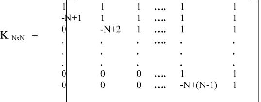
Kekre’s transform matrix [16] can be of any size NxN, which need not to be an integer power of 2. All upper diagonal and diagonal elements of Kekre’s transform matrix are 1, while the lower diagonal part except the elements just below diagonal is zero. Generalized NxN Kekre’s transform matrix can be given as,
1 1 1 …. 1 1
-N+1 1 1 …. 1 1
0 -N+2 1 …. 1 1
. . .
. . .
. . .
…. . . .
. . .
0 0 0 …. 1 1
0 0 0 …. -N+(N-1) 1
The formula for generating the element Kxy of Kekre’s transform matrix is,
1 1 1 1 1 1 1 1 1 1 1 1 -1 -1 -1 -1 1 1 -1 -1 0 0 0 0 0 0 0 0 1 1 -1 -1 1 -1 0 0 0 0 0 0 0 0 1 -1 0 0 0 0 0 0 0 0 1 -1 0 0 0 0 0 0 0 0 1 -1
H
8 =K
NxN=
5. Kekre’s Wavelet Transform (KWT)
Kekre’s Wavelet transform is derived from Kekre’s transform. From NxN Kekre’s transform matrix, we can generate Kekre’s Wavelet transform matrices of size (2N)x(2N), (3N)x(3N),……, (N2)x(N2). For example, from 5x5
Kekre’s transform matrix, we can generate Kekre’s Wavelet transform matrices of size 10x10, 15x15, 20x20 and 25x25. In general MxM Kekre’s Wavelet transform matrix can be generated from NxN Kekre’s transform matrix, such that M = N * P where P is any integer between 2 and N that is, 2 ≤ P ≤ N. Consider the Kekre’s transform matrix of size NxN shown in Figure – 3.
K11 K12 K13 … K1 (N-1) K1N
K21 K22 K23 … K2 (N-1) K2N
K31 K32 K33 … K3 (N-1) K3N
. . .
. . .
. . .
… . . .
. . .
KN1 KN2 KN3 … KN (N-1) KNN
Figure 3 – Kekre’s Transform (KT) matrix of size NxN
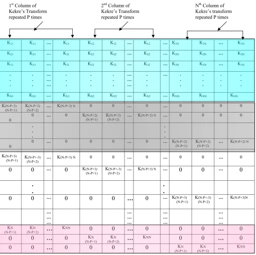
Figure - 4 shows MxM Kekre’s Wavelet transform matrix generated from NxN Kekre’s transform matrix. First N number of rows of Kekre’s Wavelet transform matrix are generated by repeating every column of Kekre’s transform matrix P times. To generate remaining (M-N) rows, extract last (P-1) rows and last P columns from Kekre’s transform matrix and store extracted elements in to temporary matrix say T of size (P-1) x P . Figure - 5 shows extracted elements of Kekre’s transform matrix stored in T.
K(N-P+2) (N-P+1) K(N-P+2) (N-P+2) … K(N-P+2) N
K(N-P+3) (N-P+1) K(N-P+3) (N-P+2) ….. K(N-P+3)N
. . .
. . .
…. …. ….
. . . KN(N-P+1) KN(N-P+2) ….. KNN
Figure 5 – Temporary matrix T of size (P-1) x P
Values of matrix T can be computed as,
T(x,y) = K( N-P+(x+1), N-P+ y) ; 1≤ x≤ (P-1) , 1≤ y≤ P
K11 K11 … K11 K12 K12 … K12 … K1N K1N … K1N
K21 K21 … K21 K22 K22 … K22 … K2N K2N … K2N
K31 K31 … K31 K32 K32 … K32 … K3N K3N … K3N
. . . . . . … … … . . . . . . . . . … … … . . . … . . . . . . . . . . . .
KN1 KN1 … KN1 KN2 KN2 … KN2 … KNN KNN KNN
K(N-P+2) (N-P+1)
K(N-P+2) (N-P+2)
… K(N-P+2) N 0 0 … 0 … 0 0 0 0
0 0 … 0 K
(N-P+2) (N-P+1) K
(N-P+2)
(N-P+2) … K
(N-P+2) N … 0 0 0 0
. . . . . .
0 0 … 0 0 0 … 0 … K
(N-P+2) (N-P+1) K
(N-P+2)
(N-P+2) … K
(N-P+2) N
K(N-P+3)
(N-P+1) K(N-P+2) (N-P+-3) … K(N-P+3) N 0 0 … 0 … 0 0 … 0
0 0
…0
K(N-P+3)(N-P+1)
K(N-P+-3) (N-P+2)
… K(N-P+3) N …
0 0
…0
.
.
.
.
0 0
…0 0 0
…
0
… K(N-P+3)(N-P+1)
K(N-P+-3) (N-P+2)
… K(N-P+3)N
… … … … … … … … … … … … KN
(N-P+1) K
N
(N-P+2)
…
KNN
0 0
…
0 0 0
…
0
0
0
…
0
KN(N-P+1) (N-P+2) KN
…
KNN0 0
…
0
0 0
…
0 0 0
…
0
KN(N-P+1)
KN
(N-P+2)
…
KNN
Figure 4 – Kekre’s Wavelet transform (KWT) matrix of size MxM generated from Kekre’s transform (KT) matrix of size NxN. Where M = N * P, 2 ≤ P ≤ N.( first Shaded part shows first N rows , Next shaded part shows next 2N to 2N+1 rows. Likewise last shaded part shows last (P-1)N + 1 To PN rows)
Example 1 (KW Transform):
Figure - 6 shows the Kekre’s Wavelet transform matrix of size 15 x 15 generated from the Kekre’s transform matrix of size 5 x 5. Here M =15, N =5 and P =M/N=3
1st Column of
Kekre’s Transform repeated P times
2nd Column of
Kekre’s Transform repeated P times
Nth Column of
Figure 6 (a) – Kekre’s Transform (KT) matrix of size 5 x 5
1 1 1 1 1 1 1 1 1 1 1 1 1 1 1 -4 -4 -4 1 1 1 1 1 1 1 1 1 1 1 1 0 0 0 -3 -3 -3 1 1 1 1 1 1 1 1 1 0 0 0 0 0 0 -2 -2 -2 1 1 1 1 1 1 0 0 0 0 0 0 0 0 0 -1 -1 -1 1 1 1
-2 1 1 0 0 0 0 0 0 0 0 0 0 0 0
0 0 0 -2 1 1 0 0 0 0 0 0 0 0 0
0 0 0 0 0 0 -2 1 1 0 0 0 0 0 0
0 0 0 0 0 0 0 0 0 -2 1 1 0 0 0
0 0 0 0 0 0 0 0 0 0 0 0 -2 1 1
0 -1 1 0 0 0 0 0 0 0 0 0 0 0 0
0 0 0 0 -1 1 0 0 0 0 0 0 0 0 0
0 0 0 0 0 0 0 -1 1 0 0 0 0 0 0
0 0 0 0 0 0 0 0 0 0 -1 1 0 0 0
0 0 0 0 0 0 0 0 0 0 0 0 0 -1 1 Figure 6 (b) - 15x15 Kekre’s Wavelet transform matrix generated from 5x5 Kekre’s transform matrix.
As shown in Figure - 6, all the columns of Kekere’s transform matrix are repeated P=3 times to generate first N=5 number of rows of Kekre’s Wavelet transform matrix. To generate remaining
(M-N) = 10 rows , extract last (P-1) = 2 rows and last P=3 columns from Kekre’s transfrom matrix and store these elements into temporary matrix T. Figure - 7 shows temporary matrix T.
-2 1 1 0 -1 1
Figure 7 - Temporary matrix T
The first row of T [-2 1 1 ] is used to generate next 5-10 rows of KW transform matrix as shown in the Figure – 6 (b) . Second row of T [0 -1 1] is used to generate last 11-15 rows of KW transform matrix.
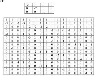
Example 2 (KW Transform):
Generating 16 x 16 KW transform matrix from 4 x 4 Kekre’s transform matrix. Here, M = 16, N = 4 and P = M/N =4.
1 1 1 1 -3 1 1 1
0 -2 1 1
0 0 -1 1
1 1 1 1 1
-4 1 1 1 1
0 -3 1 1 1
0 0 -2 1 1
0 0 0 -1 1
1st column of
KT repeated P =3 times
2ndt column of
KT repeated P =3 times
3ndt column of
KT repeated P =3 times
4th column of
KT repeated P =3 times
5th column of
Figure 8 – 4 x 4 Kekre’s transform matrix
Temporary matrix T
-3 1 1 1 0 -2 1 1 0 0 -1 1
1 1 1 1 1 1 1 1 1 1 1 1 1 1 1 1 -3 -3 -3 -3 1 1 1 1 1 1 1 1 1 1 1 1 0 0 0 0 -2 -2 -2 -2 1 1 1 1 1 1 1 1 0 0 0 0 0 0 0 0 -1 -1 -1 -1 1 1 1 1
-3 1 1 1 0 0 0 0 0 0 0 0 0 0 0 0
0 0 0 0 -3 1 1 1 0 0 0 0 0 0 0 0
0 0 0 0 0 0 0 0 -3 1 1 1 0 0 0 0
0 0 0 0 0 0 0 0 0 0 0 0 -3 1 1 1
0 -2 1 1 0 0 0 0 0 0 0 0 0 0 0 0
0 0 0 0 0 -2 1 1 0 0 0 0 0 0 0 0
0 0 0 0 0 0 0 0 0 -2 1 1 0 0 0 0
0 0 0 0 0 0 0 0 0 0 0 0 0 -2 1 1 0 0 -1 1 0 0 0 0 0 0 0 0 0 0 0 0
0 0 0 0 0 0 -1 1 0 0 0 0 0 0 0 0
0 0 0 0 0 0 0 0 0 0 -1 1 0 0 0 0
0 0 0 0 0 0 0 0 0 0 0 0 0 0 -1 1
Figure 9 - 16 x 16 Kekre’s Wavelet transform matrix generated from 4 x 4 Kekre’s transform matrix.
Properties of Kekre’s Wavelet Transform:
Orthogonal
The transform matrix K is said to be orthogonal if the following condition is satisfied.
[K][K]T = [D]
Where D is the diagonal matrix.
Kekre’s Wavelet Transform matrix satisfies this property and hence it is orthogonal. The diagonal matrix value of Kekre’s transform matrix of size NxN can be computed as
Asymmetric
As the Kekre’s transform is upper triangular matrix, it is asymmetric. Non Involutional
An involutionary function is a function that is its own inverse. So involutionar transform is a transform which is inverse transform of itself. Kekre’s transform is non involutional transform.
The Kekre’s Wavelet transform on a column vector f is given by F = [KW] f
And inverse is given by
f = [KW]T [D]-1 F
Transform on 2D Matrix
Kekre’s Wavelet transform on 2D matrix f is given by [F] = [KW] [f] [KW]T
Obtaining Inverse:
Calculate Diagonal matrix D as, [D] = [KW][KW]T
D1 0 0 0 0 0
0 D2 0 0 0 0
0 0 D3 0 0 0
0 0 0 … 0 0
0 0 0 0 … 0
0 0 0 0 0 DN Inverse is calculated as
[f] = [KW]T [ Fij / Dij ] [KW]
Where Dij = Di * Dj ; 1≤ i ≤ N and 1≤ j ≤ N
6. Information Hiding Using Kekre’s Wavelet Transform
In this section, a sterganography is implemented using Kekre’s Wavelet transform. Kekre’s Wavelet transform is first applied on full cover image. The transformed image is then divided into 16 equal non-overlapping blocks. Energy of each block is computed as summation of square of the coefficients within that block. All 16 blocks are sorted in descending order according to their energies. This Procedure was repeated on five to six images. Figure - 10 shows all 16 blocks numbered from 1 to 16. Figure - 11 shows percent energy of each block for two different cover images of size 256 x 256 transformed by KW transform generated from 128 x 128 Kekre’s basic transform.
1 5 9 13 2 6 10 14 3 7 11 15 4 8 12 16
Figure 10 - 16 blocks of the transformed cover image
82.24 4.937 8.92x10⁻⁵ 5.57x10⁻⁵
9.74 3.040 2.05x10⁻⁵ 1.86x10⁻⁵
5.39x10⁻⁵ 1.13x10⁻⁵ 4.76x10⁻¹⁰ 4.32x10⁻⁵
Figure 11 (a) Percent Energy: Horse.bmp
Figure 11 (b) Percent Energy: NewPalace.bmp
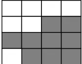
From the experimental results, it has been observed that the blocks 16,15,12,14,8,11,7,10 and 3 are the blocks containing lesser energy (Shown in Figure 12 as shaded blocks) for most of the images. Where as blocks 1, 2, 4, 5, 6, 9 and 13 are the blocks containing higher energy. So we embed the secret message into the blocks containing lesser energy as shown in Figure 12.
Figure 12 - Shaded blocks shows lesser energy blocks
6.1 The Embedding Procedure
This algorithm embeds the secret image into the lowest energy block of the transformed cover image. 1. Get the size of the Cover Image (say CxC).
2. Generate the Kekre’s Wavelet (KW) transform matrix of size CxC from the Kekre’s transform matrix of size C/2 x C/2.
3. Apply Kekre’s Wavelet (KW) transform of size CxC on full cover image. 4. Get the size of secret image to be embedded (Say MxM)
5. Generate MxM Kekre’s Wavelet(KW) transform matrix from M/2xM/2 Kekre’s transform matrix. 6. Apply Kekre’s Wavelet (KW) transform of size MxM on full secret image to be embedded. 7. Find the maximum KW coefficient of the transformed secret image.
8. Divide each KW coefficient of the secret image by its maximum coefficient. This will normalize the transformed secret image coefficients.
9. Select lowest energy block of the transformed cover image to embed the secret image. 10. Replace the selected block of the transformed cover by normalized secret image coefficients. 11. Apply inverse Kekre’s Wavelet transform on the modified cover. This gives us the stego image. 6.2 The Extraction Procedure
1. Apply Kekre’s Wavelet transform on full stego-image.
2. Extract the lowest energy block where we embedded the secret image from the transformed stego-image.
3. De-normalize the KW coefficients of the extracted data ( Multiply each KW coefficient of the extracted secret image by its maximum coefficient)
4. Take inverse Kekre’s wavelet transform of the de-normalized secret image .This gives us the recovered secret image.
7. Results and Discussion
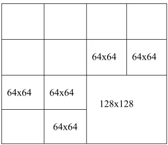
We have embedded in all six secret images into the Bitmap cover image of size 256 x 256. The following secret images were embedded into the cover image. One of size 128 x 128 in blocks 11 ,12 ,15, 16 and rest all of size 64 x 64 in blocks 7, 8, 10 ,14 and 3 respectively. Figure - 13 shows the blocks where these secret images were
embedded. Figure – 14 shows cover image and corresponding stego image resulted from embedding six secret images.
Figure 13 (a) - Six images embedded into the cover image (Embedding capacity 56.25% of the cover image size)
Cover Stego
Figure 13 (b) - Six Secret images, Cover and Stego image
Cover Stego Cover Stego
Figure 14 - Cover and corresponding Stego images Puppy.bmp and AmericanGoldFinch.bmp each of size 256X256 24 bit Bitmap images.
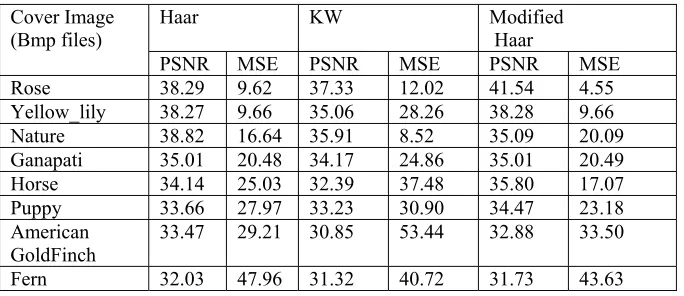
Table I summarizes the results of KW, Haar and Modified Haar transform for six different bitmap cover images. Though KW transform does not outperforms Haar transform, its performance is approachable to Haar transform. Since it is possible to generate Kekre’ Wavelet transforma matrix of any size, the cover image size need not to be integer power of 2 as in case of Haar and Modified Haar transform. Moreover Kekre’s Wavelet transform is a novel unexplored transform so even if an observer suspects that some covert communication is taking place, it is not possible to extract the secret information because attacker would not know the transform. Another advantage of KW transform is that we can generate various variations of KW transform just by changing the size of basic Kekre’s transform from which the KW transform is generated. For example 256 x 256 KW transform can be generated from 16 x 16, 64 x 64 and 128 x 128 Kekre’s transform.
64x64 64x64
64x64 64x64
128x128 64x64
Table – I – Comparison of KW, Haar and Modified Haar Transform with respect to PSNR and MSE
Cover Image
(Bmp files) Haar KW Modified Haar
PSNR MSE PSNR MSE PSNR MSE
Rose 38.29 9.62 37.33 12.02 41.54 4.55
Yellow_lily 38.27 9.66 35.06 28.26 38.28 9.66
Nature 38.82 16.64 35.91 8.52 35.09 20.09
Ganapati 35.01 20.48 34.17 24.86 35.01 20.49
Horse 34.14 25.03 32.39 37.48 35.80 17.07
Puppy 33.66 27.97 33.23 30.90 34.47 23.18
American GoldFinch
33.47 29.21 30.85 53.44 32.88 33.50
Fern 32.03 47.96 31.32 40.72 31.73 43.63
8. Conclusion
This paper presents a new unexplored image transform named ‘Kekre’s Wavelet’ transform which can be used for various applications in image processing. An image steganography using Kekre’s Wavelet transform has been implemented to show one of its applications in this area. The system embeds secret data into lesser energy blocks of the KW transformed image. From the experiments and the obtained results the proposed system achieves high hiding capacity of 56.25% of the cover image size. The quality of stego image of the proposed system is very close to original one so that the difference is imperceptible to human eye. Moreover the results of Steganography using KW transform, Haar transform and Modified Haar transform are compared. Though KW transform does not outperform Haar transform, its performance is approachable to Haar transform. Since it is possible to generate Kekre's Wavelet transform matrix of any size, the cover image size need not to be integer power of 2 as in case of Haar and Modified Haar transform. Another advantage of KW transform is that we can generate various variations of KW transform just by changing the size of basic Kekre’s transform from which the KW transform is generated. Moreover Kekre’s Wavelet transform is a novel unexplored transform so even if an observer suspects that some covert communication is taking place, it is not possible to extract the secret information because attacker would not know this transform.
References
[1] Wu, H.-C., Wu, N.-I., Tsai, C.-S, Hwang, M.-S ,”Image steganographic scheme based on pixel-value differencing and LSB replacement methods,” Vision, Image and Signal Processing, IEE Proceedings - Volume 152, Issue 5, 7 Oct. 2005.
[2] C.K Chan and L.M Cheng,” Hiding data in images by simple LSB substitution,” Pattern Recognition, Vol. 37, No. 3. (March 2004), pp. 469-474.
[3] Dr.H. B. Kekre, Ms. Archana Athawale and Ms. Pallavi N. Halarnkar, “Increased Capacity of Information Hiding in LSBs Method for Text and Image”, International Journal of Electrical, Computer and Systems Engineering, Volume 2 Number 4.
[4] Dr. H. B. Kekre, Ms. Archana Athawale, “Information Hiding using LSB Technique with Increased Capacity” International Journal of Cryptography and Security, Vol-I, No.2, Oct-2008
[5] Dr. H. B. Kekre, Ms. Archana Athawale and Ms. Pallavi N. Halarnkar, “Comparative Study of Different Color Spaces for Information Hiding using Multiple LSB’s in Different Components”, IEEE International Advance Computing Conference IACC'09, held on 6th – 7th March 09, Patiala Punjab.
[6] Dr. H. B. Kekre, Ms. Archana Athawale and Ms. Pallavi N. Halarnkar, “High Payload using High Boost Filtering in Kekre’s Multiple LSB’s Algorithm”, 2nd International Conference on Advances in Computer Vision and Information Technology ACVIT 2009, 16th -19th December 2009, Aurangabad.
[7] Dr. H. B. Kekre, Ms. Archana Athawale and Ms. Pallavi N. Halarnkar, “Increased Capacity Of Least Significant Bits Embedding For Information Hiding”,TechnoPath Technical Magazine, NMIMS University.Volume 1 No 1
[8] Dr. H. B. Kekre, Ms. Archana Athawale and Ms. Pallavi N. Halarnkar, “Polynomial Transformation To Improve Capacity Of Cover Image For Information Hiding In Multiple LSB’s ”, International Journal of Engineering Research and industrial Applications (IJERIA), Ascent Publications, Volume II, March 2009, Pune.
[9] Dr. H. B. Kekre, Ms. Archana Athawale and Ms. Pallavi N. Halarnkar, “Increased Capacity and High Security for Embedding Secret Message in Transform Domain using Discrete Cosine Transform”, Accepted in Technopath.
[10] Dr. H.B. kekre, Ms. Archana Athawale and Dipali Sadavarti,”A Novel Steganographic Scheme Using Discrete Sine Transform based upon energy distribution”, International conference on contours of computing technology, Thinkquest-2010, held on 13th,14th March ,
2010, Mumbai.
[11] Dr. H. B. Kekre, Ms. Archana Athawale, Ms. Pallavi N. Halarnkar and Mr. Varun Banura, “Performance Comparison of DCT and Walsh Transform for Steganography”, Accepted for ICWET
[13] Chin-Chen Chang, Tung-Shou Chen, Hsien-Chu Hsia, "An Effective Image Steganographic Scheme Based on Wavelet Transformation and Pattern-Based Modification,"ICCNMC Proceedings of the 2003 International Conference on Computer Networks and Mobile ComputingPage: 450 ,Year of Publication: 2003,ISBN:0-7695-2033-2.
[14] R.O.EI Safy, H.H. Zayed and A. EI Dessouki, “An Adaptive Steganographic Technique Based on Integer Wavelet Transform,” International Conference on Networking and Media Convergence, 2009 (ICNM) 2009 on 24-25 March, Cairo.
[15] P. Chen and H. Lin, “A DWT Approach for Image Steganography”, International Journal of Applied Science and Engineering 2006. 4,3 : 275-290.
[16] Dr. Kekre H. B. and Thepade Sudeep D.”,Image Retrieval using Non-Involutional Orthogonal Kekre’s Transfrom”, International Journal of MultiDisciplinary Research And Advnces in Engineering,IJMRAE, Vol.1, No.I,Novenber 2009,pp189-203.
[17] Dr. H. B. Kekre, Ms. Archana Athawale and Ms. Pallavi N. Halarnkar, “Robust and Secured Information Hiding using Polynomial Transformation in Kekre’s LUV color space and multiple LSBs”, National Conference on Information and Communication Technology NCICT-09 , held on 6th – 7th March 2009, Mumbai
[18] Adel Almohammad, Robert M. Hierons and Gheorghita Ghinea, “High Capacity Steganographic Method Based Upon JPEG ,” ARES, pp.544-549, 2008 Third International Conference on Availability, Reliability and Security, 2008, Mar-04-08 to Mar-07-08