Themed Section: Science and Technology
Design of A Commercial Building (G+7) With Flat Slab Using
Dynamic Analysis In Sap2000
Syed Khaja Mainuddin1, Syed Rizwan2, A. B. S. Dadapeer3
*1M.Tech Student, St.Mark Eucational Institution Society Group of Institutions, Anantapur, Andhra Pradesh,
India
*2 & *3Assistant Professor, Civil Engineering Department , Chiranjeevi Reddy Institute of Engineering &
Technology, Anantapur, Andhra Pradesh, India ABSTRACT
With the increase in population and development of civilization, the demand for HOUSING is increasing at a peak rate. Especially in towns due to rapid industrialization, the demand is very high. Adapting the construction of Multi-storied Building not only matches with demand but also decreases the price of the single house. Hence an Engineer to be knowledgeable about the planning and designing of such Multi-storied Buildings. Advancements of computer packages have given many tools to the designer towards achieving the best and accuracy in their work. Flat-slab building structures possesses major advantages over traditional slab-beam-column structures because of the free design of space, shorter construction time, architectural –functional and economical aspects. Because of the absence of deep beams and shear walls, flat-slab structural system is significantly more flexible for lateral loads then traditional RC frame system and that make the system more vulnerable under seismic events. Modifications with additional construction elements improve small bearing capacity of the system and increase strength and stiffness, improving seismic behaviour of flat-slab construction system. The aim of our project is to design a G+7 building with flat slabs instead of conventional slab. Analysis & Design of the building with flat slab is done by using SAP2000 software.
Keywords : Architecture, Flat slab, SAP, Bearing capacity
I.
INTRODUCTIONNow days, there is an increase in housing requirement
with increased population and urbanization.
Therefore, building sector has gained increasing prominence. However, the fact that the suitable lands for building/construction- especially in the areas in which people live intensively- are limited and expensive shows that there is a necessity for optimal evaluation of these lands. Additionally, continuously increasing prices leads to increase in building costs; so, both dimensional and cost optimization becomes necessary and even indispensable. When a building is projected, geometrical dimensions of elements belonging to carrier system of the structure are
usually determined by using engineering capability and experiences gained over time. In sizing, the tensile forces to which the material to be subjected to should comply with the specifications. In the building design, the pre-sizing details provided are generally not changed much; sizes obtained in second or – at most third solution are taken as carrier system sizes. The basic aim in the engineering is to find a design having lowest cost, and ensuring predicted limitations.
F l a t S l a b:
directly rests on the column and load from the slab is directly transferred to the columns and then to the foundation. To support heavy loads the thickness of slab near the support with the column is increased and these are called drops, or columns are generally provided with enlarged heads called column heads or capitals. Absence of beam gives a plain ceiling, thus giving better architectural appearance and also less vulnerability in case of fire than in usual cases where beams are used.
B a s i c D e f i n i t i o n o f Fl a t S l a b:
In general normal frame construction utilizes columns, slabs & Beams. However it may be possible to undertake construction without providing beams, in such a case the frame system would consist of slab and column without beams. These types of Slabs are called flat slab, since their behaviour resembles the bending of flat plates. A reinforced concrete slab supported directly by concrete columns without the use of beams.
F i g u r e : S l a b s w i t h c o l u m n s
C o m p o n e n t s o f Fl a t S l a b s
a . D r o p s : To resist the punching shear which is predominant at the contact of slab and column Support, the drop dimension should not be less than one -third of panel length in t hat direction.
b . C o l u m n H e a d s : Certain amount of negative moment is transferred from the slab to the column at the support. To resist this negative moment the area at the support needs to be increased. This is facilitated by providing column capital/heads. Flat slabs are
irregular column layouts, curved floor shapes, ramps etc. The benefits of choosing flat slabs include a minimum depth solution, speed of construction, flexibility in the plan layout (both in terms of the shape and column layout), a flat soffit (clean finishes and freedom of layout of services) and scope and space for the use of flying forms.
Fig: Solid Flat Slab
Fig: 1.3 Coffered Flat Slab
Fig: Solid Flat slab with Drop Panels
II.
METHODS OF DESIGNSome of the popular design methods are: 2.4.1 Working Stress Method.
Working Stress M e t h o d :
This is also known as MODULAR RATIO METHOD, F.O.S. METHOD and
ELASTIC METHOD.
In this method, analysis is based on the elastic theory assuming that both materials obey Hook’s Law. It is a traditional method which is used for the design of reinforced concrete design where it is assumed that concrete and steel act together and are perfectly elastic at all stages and relationship between the loads and stresses is linear up to the collapse of the structure. It is based on the criteria that the actual stresses developed in the material under the action of the working loads is limited to a set of allowable values. Thus, the sections are designed in such a way that the stresses are within the permissible limits. This leads to un-economical sections, as the method doesn’t utilize the full strength of the material resulting in heavier sections.
Design Loads = working /service loads. Design Stresses = characteristic values /F.O.S F.O.S For concrete =
3 ---- for bending
4 ---- for shear / compression
F.O.S for Steel = 1.78 ---- for bending, shear & compression.
U l t i m a t e L o a d M e t h o d :
This is also known as LOAD FACTOR METHOD. In this method, inelastic behaviour of concrete is taken into account. At the failure the material tends to behave elastically, the strain increases many times beyond those in the elastic theory and stress distribution adjusts itself to enable member t o d e v e l o p m a x i m u m c a p a c i t y . In t h i s m e t h o d , s e r v i c e l o a d s are proportioning the section to carry up to the ultimate strength of the material. Design Load = Working load * load factor
Design Stress = characteristic value / Load factor. Load Factor = 1.5 --- Concrete
= 1.15 --- Steel. DEFECTS:
This method gives slender sections but larger deflections and larger cracks. Thus, in this method serviceability is not taken care off.
Limit S t a t e Design :
It is an ideal method of design which takes into consideration not only ultimate strength but also
serviceability and durability requirement. It
includes merits of both elastic and ultimate theories. When a structure or apart of the structure becomes unfit for It is said to have reached its “LIMIT STATE”. This method is to provide an acceptable probability that the structure will not reach any limit state during its services life time.
Design loads = working loads * P.S.F. Design stress = characteristic values/ P.S.F.
P.S.F. depends on the load combinations as per cl. 36.4.1, IS-456-2000. It consists of:
Limit state of collapse.
Limit state of serviceability. Limit s t a t e o f c o l l a p s e : It is the limit state on attainment of which the structure is likely to collapse. It relates to strength and stability of the structures. Design to this limit ensures safety of structure against collapse
Limit state of collapse includes: Bending
Shear Compression Torsion Limit s t a t e o f serviceability :
It relates to performance and behaviour of structure at working loads and is
based on causes affecting serviceability of the structure. It concerns with cracking and deflection of the structure.
Limit state of serviceability includes: Deflections
Vibrations Cracking Durability
III.
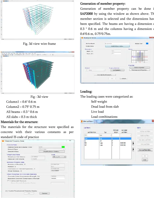
MODELLINGFig. 3d view wire frame
Fig : 3d view Column1 = 0.6* 0.6 m
Column2 = 0.75* 0.75 m All beams = 0.3 * 0.6 m All slabs = 0.3 m thick Materials for the structure:
The materials for the structure were specified as concrete with their various constants as per standard IS code of practice
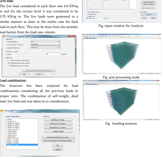
Generation of member property:
Generation of member property can be done in SAP2000 by using the window as shown above. The member section is selected and the dimensions have been specified. The beams are having a dimension of 0.3 * 0.6 m and the columns having a dimension of 0.6*0.6 m, 0.75*0.75m.
Loading:
The loading cases were categorized as: Self-weight
Dead load from slab Live load
Fig : Frame load case Live load:
The live load considered in each floor was 4.0 KN/sq m and for the terrace level it was considered to be 0.75 KN/sq m. The live loads were generated in a similar manner as done in the earlier case for dead load in each floor. This may be done from the member load button from the load case column.
Load combination:
The structure has been analyzed for load combinations considering all the previous loads in proper ratio. The combination of self-weight, dead load, live load and was taken in to consideration.
IV.
ANALYSIS AND DESIGN RESULTSAnalysis Results:
The structure was designed for concrete in accordance with IS code. The parameters such as clear cover, Fy, Fc, etc were specified. The window shown below is the input window for the design purpose.
Fig. input window for Analysis.
Fig. post processing mode
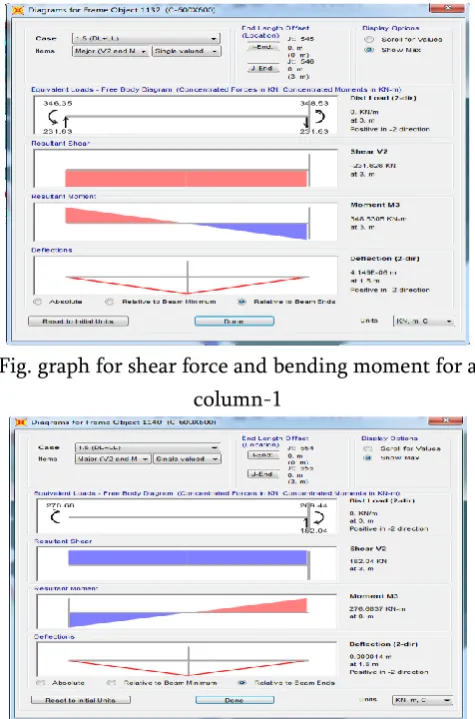
Fig. graph for shear force and bending moment for a column-1
Fig. graph for shear force and bending moment for a column-2
V.
CONCLUSIONFlat-slab building structures possesses major
advantages over traditional slab-beam-column
structures because of the free design of space, shorter construction time, architectural –functional and economical aspects. Because of the absence of deep beams and shear walls, flat-slab structural system is significantly more flexible for lateral loads then traditional RC frame system and that make the system more vulnerable under seismic events. The purely flat-slab RC structural system is considerably more flexible for horizontal loads than the traditional RC frame structures which contributes to the increase of its vulnerability to seismic effects. The critical moment in design of these systems is the slab-column connection, i.e., the penetration force in the slab at
capacity even at maximal displacements. The ductility of these structural systems is generally limited by the deformability capacity of the column-slab connection. To increase the bearing capacity of the flat-slab structure under horizontal loads, particularly when speaking about seismically prone areas and limitation of deformations, modifications of the system by adding structural elements are necessary.
VI.
REFERENCES[1].
IS: 875 (Part 1) – 1987 for Dead Loads, IndianStandard Code Of Practice for Design Loads (Other Than Earthquake) For Buildings and Structures, Bureau of Indian Standards, Manak Bhavan, 9 Bahadur Shah Zafar Marg, New Delhi 110002.
[2].
IS: 875 (Part 2) – 1987 for Imposed Loads, IndianStandard Code Of Practice for Design Loads (Other Than Earthquake) For Buildings and Structures, Bureau of Indian Standards, Manak Bhavan, 9 Bahadur Shah Zafar Marg, New Delhi 110002.
[3].
IS: 875 (Part 5) – 1987 for Special Loads andCombinations, Indian Standard Code Of Practice for Design Loads (Other Than Earthquake) For Buildings and Structures, Bureau of Indian Standards, Manak Bhavan, 9 Bahadur Shah Zafar Marg, New Delhi 110002.
[4].
IS 456-2000, Indian standard code of practice forplain and reinforced concrete (fourth revision), Bureau of Indian Standards, New Delhi, July 2000.
[5].
SP: 16-1980, Design aids for reinforced concreteto IS: 456, Bureau of Indian standards, New Delhi, 1980.
[6].
SP: 34-1987, Hand Book of ConcreteReinforcement and Detailing, Bureau of Indian Standards, New Delhi, 1987