2018; 3(1): 6-10
http://www.sciencepublishinggroup.com/j/ijimse doi: 10.11648/j.ijimse.20180301.12
ISSN: 2575-3150 (Print); ISSN: 2575-3142 (Online)
Speed Control of a Single Phase Induction Motor Using
Step-down Cycloconverter
Ayebatonye Marttyns Epemu, Kingsley Okeoghene Enalume
*Department of Electrical/Electronic Engineering, Federal University of Petroleum Resources Effurun, Effurun, Nigeria
Email address:
*Corresponding author
To cite this article:
Ayebatonye Marttyns Epemu, Kingsley Okeoghene Enalume. Speed Control of a Single Phase Induction Motor Using Step-down Cycloconverter. International Journal of Industrial and Manufacturing Systems Engineering. Vol. 3, No. 1, 2018, pp. 6-10. doi: 10.11648/j.ijimse.20180301.12
Received: December 6, 2017; Accepted: December 18, 2017; Published: May 15, 2018
Abstract:
Induction motor is a constant speed machine when operated from the mains. However it is necessary to vary thespeed of the motor in some applications. The speed of a motor basically depends on the supply frequency and number of poles. While the frequency can easily be changed without changing the entire structure of the motor, the same cannot be said for the number of poles. This paper examines the use of cycloconverters to vary the speed of single phase induction motors. Cycloconverters work on changing the supply frequency to vary the speed of the motor. With the aid of three push buttons connected to the microcontroller and the program written on it, the speed of the motor was varied in three steps, at F, F/2 & F/3. The microcontroller sends the gating pulse through an optocoupler to trigger the thyristors in a dual bridge providing the alternating signal needed to drive the motor. As the frequency decreases, the speed of the motor also decreases. The cycloconverter was used on a single phase induction motor and the result shows that it can vary the speed of an induction motor.
Keywords:
Cycloconverter, Induction motor, Motor Speed, Thyristors, Variable Frequency1. Introduction
Single phase induction motors are widely used in many household and industrial equipment/machines [1]. Basically, the induction motor is made up of a rotating part called the rotor and a stationary part called the stator [2]. Single phase power system is widely used for domestic purposes, commercial purposes and to some extent industrial purposes compared to three phase system. The power requirements in most homes, shops, and offices are small, making the single phase system economically viable in such settings. The single phase motors are simple in construction, cheap in cost, reliable and easy to repair and maintain. As a result of these advantages, the single phase induction motor finds its application in centrifugal pump, blowers, vacuum cleaner, washing machine, fans, small toys, etc. [3, 4].
The induction machine is essentially a constant speed machine when operating from mains. The difficulty in varying its speed using a cost effective means is one of its
major drawbacks [5]. To overcome these drawbacks different techniques have been developed. The speed control of an induction motor depends on factors that affect the rotor speed [6]. The rotor speed of an induction motor is shown in equations 1 and 3.
1 (1)
But,
120 (2)
Therefore, equation I becomes
1 (3)
Slip
Equation 3 shows that the speed of an induction motor depends on the supply frequency, the number of poles and the slip. Thus the speed can be varied by varying any of these three parameters leading to different methods of speed control of an induction motor. Constant voltage/frequency (V/F) method is often used for constant and variable speed control of an induction motor [5, 1]. Different techniques have been proposed for the speed control of induction motors such as varying the output voltage [7], fuzzy logic control [8], sliding mode control [9], cycloconverters [10-12], etc. Speed control by changing the frequency can be achieved through cycloconverters.
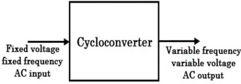
In this work, a cycloconverter was used to control the speed of a single phase induction motor. A cycloconverter is a frequency changer that converts AC (alternating current) power of a certain frequency to AC power of another frequency without the help of any intermediate DC (direct current) link. It actually converts fixed voltage, fixed frequency AC input to variable voltage, variable frequency AC output. It may be a step up converter if the output frequency were higher than the input or a step down converter if the output frequency were less than the input [13, 14]. Figure 1 shows the simplified block diagram of a cycloconverter.
Figure 1. Simplified block diagram of a cycloconverter.
Several work has been done on cycloconverters. In [15], the authors carried out analysis on cycloconverters using IGBT and MOSFET as the switching devices. MATLAB Simulink was used for the analysis. The results showed that cycloconverters can be used to vary the speed of a single phase induction motor. The analysis also showed that the total harmonic distortion in changing from IGBT to MOSFET was 0.02% indicating that any of them can be used as the switching element in the cycloconverter. In [16], the authors modelled a split phase induction motor with a single phase cycloconverter using Simulink. The simulated results showed that the speed of the induction motor can be reduced as the frequency of the supply is halved (F/2) and further reduced when it is divided by three (F/3). Figure 2 & 3 shows the simulated waveform.
Figure 2. (a.) Source voltage (b.) Output voltage waveform of single phase to single phase cycloconverter when output frequency is f/2. [16].
Figure 3. (a.) Source voltage (b.) Output voltage waveform of single phase to single phase cycloconverter when output frequency is f/3. [16].
Rajib Baran Roy & Ruhul Amin designed and constructed a single phase cycloconverter using 555 timers and
the thyristors. To ensure the output waveform of the cycloconverter is sinusoidal a Butterworth filter was used for filtering purpose [12]. Sathish Bakanagari et al developed a single phase cycloconverter using an 8051 microcontroller to control the firing pulses of the gate driving circuits. The firing angle control consists of eight MOC 3021 opto- isolators. The thyristors are arranged as two sets of bridges, positive and negative so that it conducts at different half cycles. The system has two switch selectors one for f/2 and the other for f/3. The results showed that the cycloconverter
can be used to vary the speed of an induction motor [11]. In this work, a step down cycloconverter was developed to control the speed of an induction motor in three steps (at F, F/2 & F/3).
2. System Description
The block diagram of the cycloconverter is shown in figure 4.
Figure 4. Block diagram of the cycloconverter.
2.1. Power Supply Unit
The power supply unit is responsible for providing the 5v DC required for the circuit operation. The input to this unit is 230VAC at a frequency of 50Hz and the output is 5VDC. This Unit comprises of the following basic components: 230/12V Step down transformer, Bridge Diode, 25V 1000uF Capacitor, and LM7805 Voltage Regulator.
2.2. Control Unit
This unit is made up of the PIC16F84A microcontroller and the opto-couplers. The program code for the microcontroller was written in embedded C language. The microcontroller does all the control functions of the system. It has three push buttons that acts as frequency selectors for the microcontroller. Depending on the button selected the output frequency can be F (supply frequency), F/2 or F/3. This gives 50Hz, 25Hz and 16.67Hz respectively with a corresponding duration of 20 milliseconds, 40 milliseconds and 60 milliseconds. The microcontroller controls the firing pulses of the gate driving circuit. The pulse from the microcontroller is fed to the switching unit through the optocoupler. It isolates the two power levels. The switching action of the thyristors can cause distortions in the microcontroller. The optocoupler prevent high voltages or rapidly changing voltages on one side of the circuit from damaging components or distorting transmissions on the other side.
2.3. Switching Unit
The switching unit consists of two sets of two pairs of thyristors forming two full bridges in anti-phase. Each of the optocoupler is connected to the thyristors. Triggering pulses generated by the microcontroller based on the program
written, gives the input condition to the optocoupler that drives the respective thyristor. The arrangement is such that during the positive half cycle, bridge one conducts, while bridge 2 is turned off. During the negative half cycle, bridge 2 conducts, while bridge 1 is turned off. This alternate arrangement of turning on and off the thyristors, provides the alternating voltage needed by the induction motor.
2.4. Operation of the Cycloconverter
The complete circuit of the cycloconverter is shown in figure 5. The cycloconverter has two bridges, bridge 1 (positive cycle) and bridge 2 (negative cycle). The motor is connected between the bridges. Each bridge is made up of four thyristors. Each thyristor is connected through an optoisolator to the microcontroller. The microcontroller contains the program codes that control the operation of the cycloconverter. The system is powered by 230VAC 50Hz supply that is rectified to 12VDC and then regulated to 5VDC.
Figure 5. Complete circuit of the cycloconverter.
3. Test and Results
Table 1 shows the results of the test carried out on the cycloconverter. It was used to control the speed of a single phase induction motor. As shown in the table, the cycloconverter was able to vary the speed of the induction motor as the supply frequency changes. The speed of the induction motor reduces as the frequency reduces.
Table 1. Test result for the operation of the system.
S/N Frequency Actual frequency (Hz) Period (sec) Speed of motor (rpm)
1 F 50 0.02 2800
2 f/2 25 0.04 1400
3 f/3 16.67 0.06 914.5
4. Conclusion
The single phase to single phase step down cycloconverter developed was able to generate output at frequencies less than the supply frequency. It successfully generated output frequency at F/2 and at F/3 when the corresponding switch were selected. The cycloconverter was efficiently able to vary the speed of a single phase induction motor. Although the cycloconverter was for a single phase, it can be scaled up for a three phase system with some modifications.
References
[1] G. Diyoke, C. Okeke and U. Aniagwu, "Different Methods of Speed Control of Three-Phase Asynchronous Motor,"
American Journal of Electrical and Electronic Engineering,
vol. 4, no. 2, pp. 62-68, 2016.
[2] A. P. Singh and V. K. Giri, "Modeling and Simulation of Single Phase Cycloconverter," INTERNATIONAL JOURNAL OF ENGINEERING SCIENCE & ADVANCED TECHNOLOGY (IJESAT), vol. 2, no. 2, pp. 346-351, 2012. [3] P. Morah, "Design and Construction of A Single Phase
Cycloconverter for Speed Control Applications In A Single Phase Induction Motor," Effurun, 2016.
1 2 6 4 U1 MOC3021 1 2 6 4 U2 MOC3021 1 2 6 4 U3 MOC3021 1 2 6 4 U4 MOC3021 1 2 6 4 U5 MOC3021 1 2 6 4 U6 MOC3021 1 2 6 4 U7 MOC3021 1 2 6 4 U8 MOC3021 U9 THYRISTOR U10 THYRISTOR U11 THYRISTOR U12 THYRISTOR U13 THYRISTOR U14 THYRISTOR U15 THYRISTOR U16 THYRISTOR OSC1/CLKIN 16 RB0/INT 6 RB1 7 RB2 8 RB3 9 RB4 10 RB5 11 RB6 12 RB7 13 RA0 17 RA1 18 RA2 1 RA3 2 RA4/T0CKI 3 OSC2/CLKOUT 15 MCLR 4 U17 PIC16F84A X1 CRYSTAL C1 15pF C2 15pF TR1 TRAN-2P2S BR1 BRIDGE C3 1000u VI
1 VO 3
G N D 2 U18 7805
LIVE (230V AC)
NEUTRAL
AC INDUCTION MOTOR VDD VSS 5 14 HIGH MEDIUM LOW
POSITIVE CONVERTER NEGATIVE CONVERTER
R1 1k
[4] B. Patil, R. Aute, P. Mhaske and N. Patil, "Cycloconverter To Control Speed of Induction Motor," International Research Journal of Engineering and Technology (IRJET), vol. 3, no. 4, pp. 2444-2448, 2016.
[5] P. Lole, K. Adhav, S. Gholap, S. Karkade and P. Medewar, "Speed Control of Induction Motor by Using Cyclo-converter," in National Conference on Emerging Trends in Engineering & Technology (NCETET17), 2017.
[6] B. Sai Sindura and B. Kartheek, "Speed Control of Induction Motor using Cycloconverter," International Journal of Engineering Trends and Technology (IJETT), vol. 4, no. 4, pp. 776-780, 2013.
[7] K. Sharma, B. Gupta, I. Gupta and N. Gupta, "Speed Control of Single Phase Induction Motor Using TRIAC & Reversal of Direction," Journal of Emerging Technologies and Innovative Research (JETIR), vol. 3, no. 4, pp. 152-156, 2016.
[8] N. Shaukat, B. Khan, C. Mehmood and S. M. Ali, "Takagi-Sugeno Fuzzy Logic Based Speed Control of Induction Motor," in 2016 International Conference on Frontiers of Information Technology (FIT), Islamabad, Pakistan,, 2016. [9] K. e. a. Zeb, "Indirect Vector Control of Induction Motor
using Adaptive Sliding Mode Controller," in 2016 Australian Control Conference (AuCC), Newcastle, Australia, 2016. [10] I. Ahmed and. S. Nomani, "Designing And Analysis Of
Cycloconverter To Run Variable Frequency Drive Motor,"
International Journal of Technology Enhancements and Emerging Engineering Research (IJTEEE), vol. 1, no. 4, pp. 149-153, 2013.
[11] S. Bakanagari, J. Peddapudi and M. Kumar, "A Novel Approch to Speed Control of Induction Motor by Cycloconverter with Thyristors," International Journal of Engineering Research and Applications (IJERA), vol. 3, no. 6, pp. 2159-2164, 2013.
[12] R. B. Roy and R. Amin, "Design and Construction of Single Phase Cycloconverter," International Journal of Recent Technology and Engineering (IJRTE), vol. 1, no. 3, pp. 75-82, 2012.
[13] M. Narayanan, "MATLAB Simulation of Single Phase Mid – Point Step Up and Step Down Cycloconverter," International Journal of Scientific Research in Computer Science, Engineering and Information Technology (IJSRCSEIT), vol. 1, no. 2, pp. 18-21, 2016.
[14] D. Velmurugan and N. Raman, "A Review of AC – AC Voltage and Frequency Controller," International Journal of Scientific Research in Computer Science, Engineering and Information Technology (IJSRCSEIT), vol. 2, no. 3, pp. 156-159, 2017.
[15] S. Vinodhini and S. R. Babu, "Single Phase to Single Phase Step-Down Cycloconverter for Electric Traction Applications," American-Eurasian Journal of Scientific Research, vol. 11, no. 4, pp. 271-274, 2016.