Mr. Ninad Sanzgiri Mr. Tushar Revankar
UG Student UG Student Department of Electronics & Telecommunication
Engineering
Department of Electronics & Telecommunication Engineering
Don Bosco College of Engineering, Fatorda-Goa, India Don Bosco College of Engineering, Fatorda-Goa, India
Mr. Mathias Pascoal Rodrigues
UG Student
Department of Electronics & Telecommunication Engineering Don Bosco College of Engineering, Fatorda-Goa, India
Abstract
The last few decades have seen rapid advances in information and communication technology. We commonly use broadband technology with speed Internet connectivity at our homes, offices, and in our mobile devices. The bandwidth and high-capacity requirements due to the increased use of Internet and broadband services have exceeded our expectations in twenty-first century. Optical Wireless communication (OWC) uses optical carrier in the near-infrared (IR) and visible light bands (VLC) and is considered a viable solution for realizing very high-speed and large-capacity communication links. It is a line-of-sight communication using a laser/LED to transmit the information signal between two transceivers over an unguided channel which may be either the atmosphere or free space. The technology that is used to achieve Optical Wireless Communication discussed in this paper is Li-Fi technology.
Keywords: Li-Fi, visible light communication (VLC), light emitting diode (LED), photo detector, optical wireless communication. (OWC)
________________________________________________________________________________________________________
I. INTRODUCTION
The growing congestion in the RF spectrum, and the increasing demands for higher data rates, has led to optical wireless being an active area of research. Recently, there has been progress in several areas. Solid-state lighting is becoming a viable competitor to other light sources, and the LEDs used in such applications can be used for communications as well as illumination. Visible Light Communications (VLC) originated in Japan (see work from the Visible Light Communications Consortium (VLCC) for instance [1]) and is now an active field of research worldwide, including a published IEEE standard (see [2]). In the field of more ‘traditional’ infra-red optical wireless there have been demonstrations of extremely high data rate point to point links[3], as well as systems operating at Gbit/s[4]. The energy used in optical wireless can be used to power small systems, and combining communications and power supply is attractive in certain circumstances, with recent examples of implementations [5].
There is a long history of optical wireless research applied to space applications (see for example [6]). This paper presents recent developments in indoor optical wireless, together with brief comments about their potential application in space. (It should be noted that the examples given are by no means the only ones in these well-researched areas.)
II. LI-FI TECHNOLOGY
(IJSTE/ Volume 4 / Issue 9 / 002)
Fig. 1: Environment with Li-Fi Technology.
In Li-Fi technology, the transmitter part consists of microcontroller which converts data signal into binary 0’s and 1’s where 0 represents OFF and 1 represents ON of the LED. The output appears constant as the intensity of LED is rapidly modulated which cannot be noticed by human eye. The transmitted signal is received by photo detector and amplified to remove noise and then regenerated into desired signal. The regenerated signal should be able to read by the computer.
The frequency ranges used by Li-Fi is between 400THz to 800THz. Li-Fi uses visible light spectrum to obtain high data rates of 500 mbps practically and can reach up to 10Gbps. Parallel transmission is done embedding an array of LED’s or by using green, red, blue LED’s which has different frequency range to obtain high data rates.
III. WORKING TECHNOLOGY
Li-Fi based Bidirectional Transmission
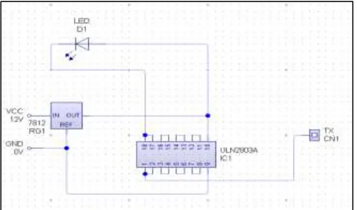
The block diagram of the bidirectional system for transmission of data and image using Li-Fi technology is given in Figure-2. The transceiver section on both sides has the ability to transmit and receive data simultaneously. In transmitter section, the input data is converted into binary information which is given to LED driver. It drives the binary information to the high illumination LED. In the receiver section, the photo detector (solar panel) receives the binary information and amplifies it using amplifier and then inverted using 74LS14. The original message is then obtained in the output display.
current is converted into voltage. The second stage is inversion of voltage level to get the original information by the Hex Schmitt trigger IC 74LS14.
Fig. 4: Photo detector receiver circuit.
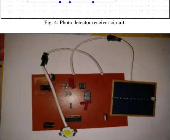
Fig. 5: Hardware model of the transceiver circuit. Figure-5 shows the hardware model of the transceiver circuit.
IV. RESULTS & DISCUSSIONS
Simulation Output for Data Transmitter
(IJSTE/ Volume 4 / Issue 9 / 002)
Fig. 6: Simulation result of data receiver. Simulation Output for Data Receiver
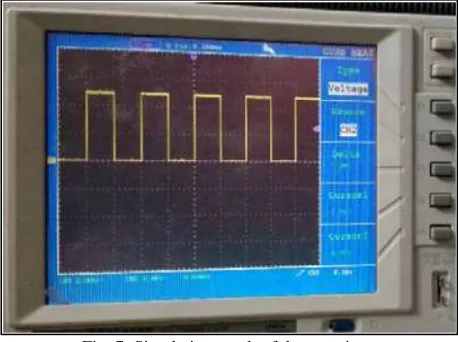
The receiver circuit has two stages First stage converts the photo detector current to voltage signal by a comparator. In second stage, hex inverter IC inverts the signal one more time to get the original information. The solar panel current varies according to changes in light illumination. Figure-7 represents the output simulation of data receiver circuit.
Fig. 7: Simulation result of data receiver. V. CONCLUSIONS
Li-Fi technology can be implemented to obtain high speed data transfer. This paper describes about Bidirectional transmission using Li-Fi. The future scope in Li-Fi technology is to apply in hospitals since radio waves cause harmful effects on humans. Similarly, using radio frequencies in nuclear power plants is dangerous and this can be replaced with Li-Fi. It can also be used in aviation as it doesn’t interfere with radio frequencies. Ultrasonic sensors uses big antennas which increases the complexity of the network and not efficient in transmission of data with respect to speed and distance. The limitations for exploring the ocean beds can be improved using Li-Fi technology in underwater communication. This shows that, this is the only technology which is cleaner, greener and safe in communication system.
REFERENCES
[1] M. Samuel Lazar, T. Ravi. 2015. Li-Fi Design for High Speed Data Transmission. Asian Research Publishing Network of Engineering and Applied Sciences (APRN), ISSN 1819-6608, 10(14).
[2] Abhishek Kurup, Vipin Tiwari, Selvanathiya. 2014. Implementation and Demonstration of Li-Fi Technology. International Journal of Research in Engineering and Technology (IJERT), pISSN: 2321- 7308, 3(03).
[3] Akshata M Sonnad, Anjana Gopan, Sailakshmi N R, Divya S, Ambika R. 2013. Recent Advancements in Li-Fi Technology. International Journal of Electrical, Electronics and Data Communication, ISSN: 2320- 2084, 1(10).
[4] S. Ranjith, T. Ravi, P. Umarani, and R. Arunya. 2014. Design of CNTFET based sequential circuits using fault tolerant reversible logic. International Journal of Applied Engineering Research. 9(24): 25789-25804.
[5] C. Periasamy, K. Vimal, D. Surender. 2014. LED lamp based visible light communication in underwater vehicles. International Journal of Engineering Trends and Technology (IJETT), ISSN: 2231-5381, 13(3).