E X P R E S S P A P E R
Open Access
Controlling translucency by UV printing
on a translucent object
Tsuyoshi Takatani
*, Koki Fujita, Kenichiro Tanaka, Takuya Funatomi and Yasuhiro Mukaigawa
Abstract
UV printer, a digital fabrication tool, can print 2D patterns on 3D objects consisting of various materials by using UV inks which immediately dry through being exposed to ultraviolet light. In general use, the translucency of the materials is removed by printing a matte white layer. On the other hand, we propose a method to control the translucency of a printed object by rather utilizing both of the translucency of the materials and inks without printing the white layer. A key is to fuse two different manners: example based and physics based. We apply Kubelka’s layer model with few measurements to render the translucency and then build a lookup table between a combination of factors in print and the fabricated translucency. The lookup table is used for finding the best combination to represent an input query about translucency. The rendering method is quantitatively evaluated, and in experiments, we show the proposed system can control the translucency through replicating appearance.
Keywords: UV printer, Translucency, Appearance fabrication
1 Introduction
Digital fabrication tools, such as 3D printer and CNC router, allow us to easily build a complex-shaped object, and hence are often applied to make a custom-built object, e.g., personal prosthetic limb. Since not only shape but also appearance is an important factor for our visions, techniques to control the appearance in digital fabrication are required.
To control color, a factor of the appearance, there are some commercial 3D printers that can build a colorful object. Brunton et al. [1] increased the number of con-trollable colors in 3D printing by utilizing natural error diffusion. Weyrich et al. [2] controlled glossiness, a fac-tor of the appearance, by using a CNC router. Hašan et al. [3] and Dong et al. [4] controlled translucency, also a fac-tor of the appearance, by using a 3D printer. Papas et al. [5] replicated both of the color and translucency by mix-ing different pigments. The above methods for controllmix-ing the translucency modify inside of the object. In contrast, our purpose is also to control the translucency but by modifying outside of the object.
In this paper, we propose a method to control the translucency by using a UV printer, which can print 2D
*Correspondence:[email protected]
Nara Institute of Science and Technology (NAIST), Ikoma, Nara, Japan
patterns on 3D objects consisting of various materials, such as plastic and metal. When putting an ink on a base material, the translucency of the printed object depends on both the translucency of the material and ink because of subsurface scattering, as shown in Fig.1. The translu-cency can be modified by a combination of factors, such as base material, color of an ink, and the number of printed layers. The proposed method controls the translucency by UV printing through changing such a combination.
Three contributions of this paper are to propose a novel approach using a UV printer for controlling the translu-cency, fuse two different manners for resolving tradeoffs, and implement the working system.
2 Controlling translucency by UV printing
In general, a UV printer prints the bottom layer with a matte white ink to remove the translucency of base mate-rials. On the other hand, we rather utilize the translucency without printing the white layer. The translucency of the printed object depends on both of the translucency of the base materials and inks and can be changed by a com-bination of the factors. If the translucency of the printed objects in all combinations can be measured, it is easy to control the translucency in an example-based manner. However, it is almost impossible to print and measure in
a
b
Fig. 1The translucency of a fabricated object.aThe fabricated object consists of a UV ink layer on a white wax.bIncident light is scattered inside of both of the ink layer (red) and base material (blue), called subsurface scattering, and hence, the radiated light (purple) is a mixture of them
all the combinations. Therefore, we fuse such a manner with a different manner based on physics model.
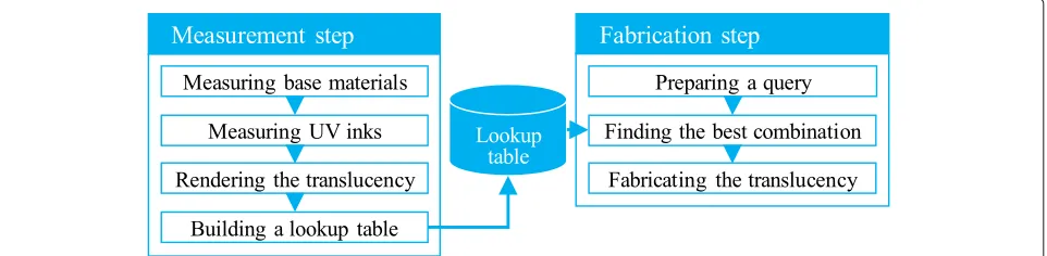
The proposed method consists of measurement and fab-rication steps, as shown in Fig.2. In the measurement step, the individual translucencies of the base materials and inks are measured. The translucency of the printed object in a combination is rendered based on a physics model. The translucency in all the combinations can be ren-dered by simulation with few measurements. Therefore, it enables to build a lookup table between the combina-tions and translucency, like the example-based manner. In the fabrication step, given a query about translucency, either measured or manually designed, a combination can be found in the lookup table so that the translucency of the printed object is the most similar to the query. The rest of this section explains the rendering method, mea-suring the translucency, and building the lookup table and finding the best combination.
2.1 Rendering the translucency of a layered object
The translucency of the printed object depends on both of the translucency of the base material and ink, as men-tioned above. A key feature is that the printed object has a layered structure, as shown in Fig. 1b. Thus, we apply Kubelka’s layer model [6] to render the translucency.
The original model formulates scalar reflectance r and transmittancetof a two-layered object, as follows:
⎧ ⎨ ⎩
r=r1+t12r2(1+r1r2+ · · ·)=r1+ t
2 1r2
1−r1r2, (1) t=t1t2(1+r1r2+ · · ·)= 1−t1rt12r2, (2)
wherer1andt1are the reflectance and transmittance of the top layer andr2andt2those of the bottom one, respec-tively. Now, let us take subsurface scattering into consid-eration because it is a main cause why an object looks translucent. Since subsurface scattering diffusely spreads light, it is modeled by point spread function (PSF). The PSF can also be separated into reflective and transmissive PSFs. The reflective and transmissive PSFs of the top layer are defined asR1(x),T1(x), respectively. As well, those of the bottom one are defined asR2(x),T2(x). The reflective PSF of the two-layered object is, therefore, written as
R(x)=R1(x)+((T1∗R2)∗T1)(x)
+((((T1∗R2)∗R1)∗R2)∗T1)(x)+ · · ·, (3) where “∗” is the convolution operator. The transmissive PSF can also be written as well but it is omitted here for saving the space. By Fourier transform, Eq. (3) is transformed into
F[R]=F[R1]+F[T1]F[R2]F[T1]+ · · ·
=F[R1]+ F
[T1]2F[R2] 1−F[R1]F[R2]
, (4)
whereF[·] means Fourier transform and the argumentx
is omitted. If the PSFs are isotropic, the imaginary parts in the frequency domain become zero. Therefore,F[R] can be regarded as the reflective modulation transfer function (MTF), which is defined asRˆ(fx), wherefx is the spatial
frequency. Finally, the reflective and transmissive MTFs of the two-layered object are written, as follows:
⎧ ⎪ ⎨ ⎪ ⎩ ˆ
R(fx) = ˆR1(fx)+ Tˆ1
2 (fx)Rˆ2(fx)
1− ˆR1(fx)Rˆ2(fx), (5) ˆ
T(fx)= 1− ˆTˆR1(fx)Tˆ2(fx)
1(fx)Rˆ2(fx), (6)
whereAˆ(fx)means the corresponding MTF to a PSFA(x).
Once the individual reflective and transmissive MTFs of the base materials and inks are given, those of the printed object can be rendered by using Eqs. (5) and (6). Recur-sively applying Eqs. (5) and (6), it is also possible to render the MTFs of a multi-layered object.
2.2 Measuring the modulation transfer functions
The MTFs are employed for explaining the translu-cency, as mentioned above. In this paper, to measure the MTFs, we apply the modulated imaging, proposed by Cuccia et al. [7] for measuring the quantitative scattering and absorption coefficients of a medium. The modulated imaging is based on measuring MTFs in a Pro-Cam sys-tem. Projecting a sinusoidal pattern onto the medium, light scattering in the medium blurs the pattern, and hence, the amplitude of the measured sinusoidal pattern is attenuated in comparison with that of the projected one. The MTF consists of the rates of attenuation at different frequencies. We refer the readers to [7] for the details.
We can directly measure the MTFs of the base materi-als in the Pro-Cam system. However, it is impossible to directly measure the MTFs of the inks because the ink layer has to be printed on an object. Therefore, we esti-mate those by utilizing Eq. (5). As printing an ink whose reflective and transmissive MTFs are Rˆ1(fx) and Tˆ1(fx),
respectively, on a mirror, the reflective MTF of the printed objectMˆ1(fx)is, as below:
ˆ
M1(fx)= ˆR1(fx)+
ˆ T1
2
(fx)
1− ˆR1(fx)
, (7)
where we assumeRˆ2(fx) = 1 in Eq. (5) because of only
specular reflection on a mirror. Also, as printing the same ink twice, the reflective MTFMˆ2(fx)is, as below:
ˆ
M2(fx)= ˆR1(fx)+
ˆ T1
2
(fx)Mˆ1(fX)
1− ˆR1(fx)Mˆ1(fX)
. (8)
Now, the reflective and transmissive MTFs of the ink,
ˆ
R1(fx)andTˆ1(fx), can be estimated from Eqs. (7) and (8)
at least because both ofMˆ1andMˆ2can be measured. It is also possible to increase the number of the same ink layers and then use it for a stable estimation in a least-squares method.
2.3 The lookup table
Finally, it is possible to build the lookup table by using the rendering method with the measurements. The base materials should be translucent, such as rubber and wax, not transparent and opaque.
The lookup table is built by rendering in all the com-binations. Building the lookup table is a time-consuming process but it is required only once.
In the fabrication step, given a query about translucency, a combination is searched in the lookup table so that the translucency of the printed object is the most similar to the query. Here, it is required to define distance for rep-resenting how much a MTF is close to another. Thus, we
a
b
Table 1The RMSEs of the rendered MTFs in comparison with the measured ones
Base materials
Inks Plastic eraser Wax candle Milky acrylic Average
Cyan 0.0242 0.0838 0.0548 0.0543
Magenta 0.0676 0.0726 0.0918 0.0773
Yellow 0.0741 0.1127 0.1861 0.1243
Average 0.0553 0.0897 0.1109 0.0853
employ a root-mean-square error (RMSE) for that. The distanceEABbetween MTFsAˆ(fx)andBˆ(fx)is defined as
EAB= |F1|
fx∈F
ˆ
A(fx)− ˆB(fx) 2
, (9)
where F is a set of discrete frequencies to be used for calculating the distance.
3 Experiments
We make experiments for evaluating the rendering method and the whole system. For the measurements, we constructed a Pro-Cam system with a projector (Vivitek QUMI Q8) and an RGB camera (FLIR Grasshopper3
Color). In the experiments, we use three base materials: a plastic eraser, a wax candle, and a piece of milky acrylic board.
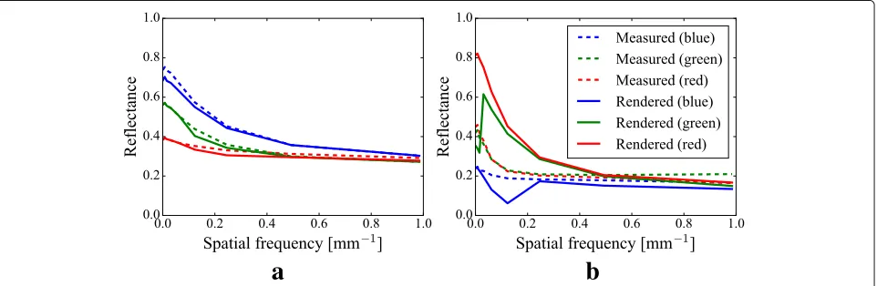
3.1 Quantitative evaluation of the rendering method
The rendering method plays an important role in the proposed method because the lookup table is based on that. Hence, firstly, we quantitatively evaluate the ren-dering method. In this evaluation, the reflective MTFs of the printed objects in several combinations are ren-dered and then compared with those which are mea-sured through being fabricated. Here, we use three inks: cyan, magenta, and yellow. As examples of the results, the rendered MTFs, as solid lines, and the measured ones, as dashed lines, in three channels are shown in Fig. 3, in which (a) is a case of the cyan on the eraser and (b) the yellow on the acrylic. In Fig.3a, the rendered MTFs are very similar to the mea-sured ones, whose RMSE is on average 0.0242. On the other hand, in Fig. 3b, both of them are less similar, whose RMSE is on average 0.1861. The other RMSEs are written in Table 1 and the totally averaged RMSE is 0.0853. Since the range of reflectance is in 0 to 1, it can be said that the error is on average 8.53%. We believe that is reasonable for building the lookup table.
a
b
c
d
e
f
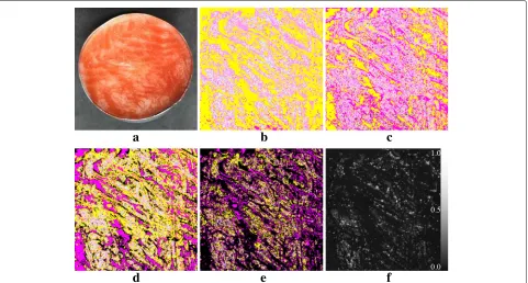
Fig. 5Replicating the reflective MTFs of the salmon.aThe printed object.b–eThe four layer images from the bottom to the top.fThe error map
3.2 Controlling the translucency for replication
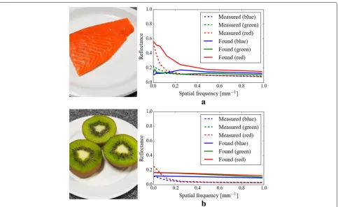
We make experiments for controlling the translucency of the printed object. The lookup table is built with the three base materials and fifteen inks. Though only the inks of 100% were used in the previous experiment, the same inks of 20, 40, 60, and 80% are also used for building the lookup table here. Setting the maximum number of printed layers to five, it results in 2,440,845 elements in the lookup table. A query about translucency can be manually designed, but it is easier to measure a real-world object. We, therefore, measure the reflective MTFs of a slice of salmon and kiwi, as shown in Fig. 4, and a small region of those is used as a query. As a result of finding the best combination to the salmon, it was to print in the order of the magenta of 40%, yellow of 100%, magenta of 100%, and magenta of 100% on the wax candle, whose RMSE was 0.0812. As well, the best combination to the kiwi was to print in the order of the cyan of 100%, magenta of 40%, magenta of 40%, magenta of 40%, and yellow of 60% on the wax can-dle, whose RMSE was 0.0714. The results are shown in Fig.4.
Moreover, we make an experiment for replicating the reflective MTFs of the whole salmon pixel by pixel. According to the previous experiment, the wax candle suits to the MTF of the salmon; thus, a part of the lookup table where the base material is the wax candle is used for finding the best combination for each pixel. As the result, an image of the printed object is shown in Fig.5a, which consists of four layers of inks on the wax candle. The layer
images and the error map are shown in Fig.5b–eandf, respectively.
4 Conclusion
In this paper, we proposed a novel method to control the translucency by UV printing on a translucent material. We applied Kubelka’s layer model with few measurements to render the translucency of the printed object and then built the lookup table. Given a query about translucency, it is possible to find a combination of the factors in print, such as base materials, inks, and the number of printed layers, in the lookup table so that the translucency by the combination is the most similar to the query. That is, we can control the translucency of the printed object.
There are some limitations. Currently, we assume the PSFs are isotropic but some real-world objects has anisotropic PSFs. Since the printhead of a conventional UV printer moves within a 2D space, it is difficult to print on a complex-shaped object but a transfer sheet for UV printing could resolve that problem.
Funding
This work is partly supported by ACT-I, JST, grant JPMJPR17UG, and JSPS KAKEN grants JP17J05602 and JP17K19979.
Availability of data and materials
The data in this manuscript will not officially be shared because of the originality of its file format.
Authors’ contributions
edited the manuscript. TF is a co-supervisor and edited the manuscript. YM is a supervisor and edited the manuscript. All authors reviewed and approved the final manuscript.
Competing interests
The authors declare that they have no competing interests.
Publisher’s Note
Springer Nature remains neutral with regard to jurisdictional claims in published maps and institutional affiliations.
Received: 2 April 2018 Accepted: 17 May 2018
References
1. Brunton A, Arikan CA, Urban P (2015) Pushing the limits of 3d color printing: error diffusion with translucent materials. ACM Trans Graph 35(1):4–1413.https://doi.org/10.1145/2832905
2. Weyrich T, Peers P, Matusik W, Rusinkiewicz S (2009) Fabricating microgeometry for custom surface reflectance. ACM Trans Graph 28(3):32–1326.https://doi.org/10.1145/1531326.1531338
3. Hašan M, Fuchs M, Matusik W, Pfister H, Rusinkiewicz S (2010) Physical reproduction of materials with specified subsurface scattering. ACM Trans Graphics (Proc. SIGGRAPH) 29(3).https://doi.org/10.1145/1778765.1778798
4. Dong Y, Wang J, Pellacini F, Tong X, Guo B (2010) Fabricating
spatially-varying subsurface scattering. ACM Trans Graph 29(4):62–16210.
https://doi.org/10.1145/1778765.1778799
5. Papas M, Regg C, Jarosz W, Bickel B, Jackson P, Matusik W, Marschner S, Gross M (2013) Fabricating translucent materials using continuous pigment mixtures. ACM Trans Graph 32(4):146–114612.https://doi.org/10. 1145/2461912.2461974
6. Kubelka P (1954) New contributions to the optics of intensely
light-scattering materials. Part II: Nonhomogeneous layers∗. J Opt Soc Am 44(4):330–335.https://doi.org/10.1364/JOSA.44.000330