Numerical Homogenization of Protective Ceramic Composite
Layers using The Hybrid Finite-Discrete Element Methods
Zainorizuan Mohd Jaini
1,*, Yuan Tian Feng
2, Shahrul Niza Mokhatar
1and
Mazlan Abu Seman
31
Jamilus Research Center, University Tun Hussein Onn Malaysia, 86400 Parit Raja, Johor, MALAYSIA.
2
Civil and Computational Engineering Center, Swansea University, SA2866 Singleton Park, Swansea, UK.
3
Faculty of Civil and Earth Resources, University Malaysia Pahang, 26300 Gambang, Pahang, MALAYSIA.
Received 28 June 2011; accepted 5 August 2011, available online 24 August 2011
1.
Introduction
Effects of high rate loading on concrete structures are highly likely to cause substantial local and global damage. For a concrete structure loaded by ballistic or explosion, the progressive damage take only a fraction of second subsequently leads to a total structural collapse. Therefore, numerous investigations in both experimental and numerical works have been conducted in order to provide more effective structural protection. Currently, many studies in protective structures have exerted the fibre reinforced polymers [1,2] or aluminium foam composites [3,4] to protect structures from the massive energy of blast loading. However, the ability of these materials is presently limited to prevent damage in the moderate level.
Meanwhile, innovative technologies have resulted in more effective ceramic composite as high rate loading-resistance and protective layer. The ceramic composite layer consists of ceramic frontal plate and softer-strong reinforced polymer network. These materials serve specific purposes of defeating high rate loadings and maintaining the structural integrity of the layer [5]. Ceramic composite has been vastly applied in ballistic and explosion resistances, many exclusively for the military purposes as the material has paramount functions
in absorbing and dissipating kinetic energy. Ceramic composite layer has showed ample success in lowering damage and enhance the performance of structures. Several studies [6-9] have shown that ceramic composite has high potential to sustain reinforced concrete structures from further damage when subjected to ballistic or explosion.
Since ceramic composite layer is produced by combining two different artificial materials, the complexity of the constituent model would almost be intractable analytically and make the computational solution prohibitively expensive in the heterogeneous manner. Alternatively, the homogeneous material model is a subject of considerable practical and theoretical interest [10]. The homogenisation approach provides an appropriate framework to relate the material properties in an equivalent manner. This can be achieved based on the numerical estimation of the mechanical response of the material in microstructure level. Basically, the simplest of the analytical strategies by the rule of mixtures can be adopted with assumption that the overall linear elastic behaviour of the composite material is given by the average of the corresponding microscopic values of each constituent phase weighted by the respective volume fractions. However, the rule of mixtures does not generally provide a very accurate estimate of composite Abstract: Innovative technologies have resulted in more effective ceramic composite as high rate loading-resistance and protective layer. The ceramic composite layer consists of ceramic frontal plate that bonded by softer-strong reinforced polymer network, consequently gains the heterogeneous condition. These materials serve specific purposes of defeating high rate loading and maintaining the structural integrity of the layer. Further due to the lack of a constituent material and tedious problem in heterogonous material modelling, a numerical homogenization is employed to analyse the isotropic material properties of ceramic composite layer in homogenous manner. The objective of this study is to derive a constitutive law of the ceramic composite using the multi-scale analysis. Two-dimensional symmetric macrostructure of the ceramic composite was numerically modelled using the hybrid finite-discrete element method to investigate the effective material properties and strength profile. The macrostructure was modelled as brittle material with nonlinear material properties. The finite element method is incorporated with a Rankine-Rotating Crack approach and discrete element to model the fracture onset. The prescribed uniaxial and biaxial loadings were imposed along the free boundaries to create different deformations. Due to crack initiation on the macrostructure, the averaged stresses were calculated to plot the stress-strain curves and the effective yield stress surface. From the multi-scale analysis, the rate-dependency of Mohr-Coulomb constitutive law was derived for the ceramic composite layer.
(5)
(6) (3)
(4) material behaviour as it takes no account of interactions
between different phases. A confident and accurately technique to determine the mechanical and material properties of the ceramic composite is dependable on the multi-scale analysis.
2.
Multi-Scale Analysis
More common and longer established examples of heterogeneous engineering materials such as reinforced concrete, fibre polymer and laminated timber have been treated as homogenous material. As a result, the principles to evaluate the equivalent mechanical behaviour of the heterogeneous materials using a multi-scale analysis have been confidently developed in various levels from macroscale up to microscale [11-14].
2.1
The representative volume element
Central to homogenisation approach is the concept of the representative volume element (RVE). The RVE is a microscopically scaled continuum domain containing a distribution of materials that considered to be representative of the microstructures of the heterogeneous material. Fig. 1 shows the RVE of heterogeneous in a unit cell of structure. Homogenisation approach has two essential steps [10], localisation (macro to micro transition) and homogenisation proper (micro to macro transition). Localisation consists of determining the microscopic fields over the RVE from given macroscopic values while the homogenisation proper consists of calculating overall macroscopic variables from the micro fields. In the multi-scale analysis, the numerical solutions of the RVE can be achieved by solving a micro level boundary value problem at each Gauss point.
Fig. 1 The representative volume element from microscale structure to a unit cell structure.
In the case where RVE constituents are linear elastic and the material is assumed as isotropic, a single loading is sufficient to determine the effective shear and bulk modulus. In the finite element method, this can be easily conducted using the implicit procedure. Some studies [15,16] have applied simple load histories such as incremental uniaxial stretching or shear to the RVE in order to obtain homogenised stress-strain curves. Basically, the kinematic constraint is imposed to ensure that the motion of the RVE is driven by the history of the macroscopic deformation and enforced consistency between microscopic and macroscopic stress power [10].
Further kinematical constraints may be applied to obtain different classes of homogenised constitutive models.
2.2
Periodic boundary conditions
In the numerical homogenisation, composite materials are assumed to be periodic and consists a lot of repeating cells. A unit cell is very small when compared to the whole body of the material, but it is big enough to represent all the heterogeneous behaviour of the material. Homogenisation approach uses asymptotic expansion to solve problems relating to periodic. For the periodic structure material, function that represents its physical properties has the following form:
where is the position vector of the point
M, and is a constant vector that determine the period of the structure. The periodic function of the elastic constant can then be written as:
Periodic boundary condition is a widely used in dynamic microstructure. When periodic boundary conditions are used, all cells are connected and do not sense the existence of a free surface [17]. This allows structure to split into autonomous units due to periodic behaviour of constituent materials.
2.3
The strain tensor
If the cell domain undergoes a displacement, the local periodicity hypothesis [18] ensures that composite material, despite its deformation, retains its periodicity relation with its neighbouring cells. Consequently, the periodicity vector can be written as:
where and is the displacement
difference between the periodic points. The transformation of the cells space is related to the change of periodicity vectors. Therefore, the average strain components of a unit cell on macroscopic can be evaluated as:
where and refer to the dimensions of the cell respectively. Equations (4) to (6) are known as the homogenized strain components and are related to the change of periodicity vectors.
(1)
(9) (8) (7)
(10)
(11)
(12)
(13)
(14)
(15)
(16)
(17)
(18)
2.4
The simplified homogenized method
By using the simplified homogenisation method, a unit cell is restrained at particular sides of the cell’s boundaries and appropriate prescribed displacement loadings are applied at the released boundaries. If only plain strain conditions are considered, therefore the elasticity tensor of plain strain can be substituted into the linear stress-strain relation given by equation (7).
where C is called as the elasticity tensor. As the plain strain analysis is used, the stress-strain relation gives:
The applied displacement is incrementally increased and the reaction forces in both x and y directions are calculated for each displacement applied. It is then possible to calculate the stress for each strain value and hence plot a stress-strain curve. Due to the boundary conditions and uniaxial loading, the stress-strain relation can be further simplified. The stiffness matrix for a composite material in plain strain is given by:
where is the stress in the x-direction, is the stress
in the y-direction, is the strain, is the equivalent
Young’s modulus of the RVE and is the equivalent Poisson’s ratio. When expanded, this yields the equations for stress in the x-direction and stress in the y-direction:
Solved simultaneously, these yield the equations for calculating the equivalent Young’s modulus and equivalent Poisson’s ratio of the RVE:
When a unit thickness is used in the finite element analysis, the forces are found to be equivalent to the stress. The strain is therefore found to be equal to 1. Thus, the equivalent of Young’s modulus and equivalent Poisson’s ratio can be simplified as:
where and are the reaction forces that produced on
the boundary of the unit cell in x-direction and y-direction respectively.
3.
The Hybrid Finite-Discrete Element
Method
The hybrid finite-discrete element method is recently developed to model the problems of solid mechanics where crack, fracture or other types of extensive material damage are expected. The method combines the finite element approach and the discrete element method to model the transition from continuous to discontinuous of solid bodies. The hybrid finite-discrete element method has been generally developed in order to simulate the geomechanics problems [19-21]. This method has been further developed to various irregular and deformable particles in many applications.
3.1
The material modelling
Ceramic composite as quasi-brittle material shows pressure dependent strength properties and has various state of stress which produces different failure modes. Therefore, the time independent elastoplastic model is often used to describe the stress-strain relationships of ceramic composite where the material is linearly elastic up to the yield point and then becomes perfectly plastic. The simplest material model which incorporates this pressure dependency and is able to predict the stresses on the failure plane is the Mohr-Coulomb criterion. The Mohr-Coulomb yield criterion is a generalisation of the Coulomb friction failure law and is defined by:
(19)
(20)
(21)
(22)
(24) (23) to quasi-brittle problems. The strength of Mohr-Coulomb
is written as:
where and are the principal stresses, is the constant parameter dependent to the friction angle, and the unconfined compression strength, is defined according to the values and . In condition when the cohesion, is greater than zero, the Mohr-Coulomb model predicts a tensile strength which is larger than the tensile strength observed experimentally. This discrepancy can be mended by introduction of a tension cut-off in the form of complete Rankine tensile corner as opposed to a hydrostatic cut-off [22]. The Rankine tensile corner introduces additional yield criteria defined by:
where refers to each principal stress at and is the tensile strength or tension cut-off, which is the highest tensile stress allowed in the material. Although at present no explicit softening law is included for the tensile strength, indirect softening does result from the degradation of cohesion according to the following criteria:
This ensures that a compressive normal stress always exists on the failure shear plane. The Rankine part of the criterion is taken to be associated whereas the Mohr-Coulomb part is non-associated [22]. The combination of these criteria is usually referred to as the Modified Mohr-Coulomb criterion [23].
3.2
Crack and fracture formation
Ceramic composite layer is represented as a continuum from which cracking virtually occurs during deformation process. The crack then propagates to all directions when the material strength is degraded. Before experiencing any failure, the material will remain in homogenous elastic state. The commonly accepted Rankine and Rotating Crack models are used to simulate crack formation within a continuum description under tensile conditions [24]. In this approach, cracks are initiated when limiting tensile stress is reached, after which the material follows a softening or damaging response governed by an appropriate relation. The formation and growth of cracks within a quasi-brittle material occur in directions that attempt to maximize the strain energy density [25]. The initial failure surface for the Rankine and Rotating Crack models can be defined by tensile surface failure as represented by:
where are the principal stress invariants and is the tensile strength of material.
After the initial yield, the Rotating Crack formulation represents the anisotropic damage evolution by degrading the elastic modulus in the direction of the major principal stress invariant. The strength degradation will occur in all stress directions implied by the following equation.
where is the damage parameter and is the local
stress at the local coordinate system associated with principal stresses. The damage parameter is dependent on the fracture energy, which is denoted as:
The Rankine model uses the same softening model however it is applied within a continuum material formulation rather than by following the direction of cracks or micro-cracks at Gauss point.
3.3
Contact discontinuities
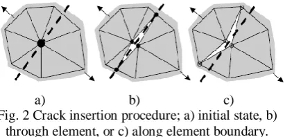
In the hybrid finite-discrete element method, damage and fracture patterns are obtained when the topology of the mesh is updated by insertion of discrete fracture in the failed region. A discrete fracture is introduced when the tensile strength in a principal stress direction reaches zero and is oriented orthogonal to this direction. The fracture can be inserted along failure plane (intra-element fracture) as can seen in Fig. 2, resulting in creation of new node and formation of new element in finite element system, or along the boundaries (inter-element fracture) of the existing elements [25,26]. This evolution process is continued until either the system comes to equilibrium or up to the time of interest.
Fig. 2 Crack insertion procedure; a) initial state, b) through element, or c) along element boundary.
During the crack and fracture in which elements are separated, the condition of contact between finite elements and discrete elements is complied with the penalty method based on contact surface deformation theories [27,28]. The behaviour of post-failure is coupled to the tensile softening response and the discrete element contact parameters are introduced to control the element separation and assuring the maintenance of energy balance during the discrete discontinuous transition period. The parameters included the contact damping, the contact field, the values of normal and tangential penalties, size of buffer zone for contact detection and the limit size of the element after fracturing [26,29].
(25)
(27) (26)
4.
Isotropic Fracture Models
Consider a unit cell has enough characteristic length and the condition of ceramic is perfect without any defects. Because of the properties governing its respective constituents are assumed to be known and isotropic over the domain, the homogenised material therefore is also isotropic. In order to more accurately represent the material behaviour, the non-linear models is adapted to include fracture.
4.1
Model description
A symmetric unit cell is chosen with side length equal to 20.40mm as illustrated in Fig. 3. The linear triangular unstructured elements were used for the hybrid finite-discrete element model. The Rankine-Rotating Crack strain plasticity model and linear elastic constitutive law were selected for the analysis. The material properties assigned to the model are shown in Table 1. The ceramic material was modelled as a brittle material able to fracture and the polymer material is assumed to be a linear elastic material.
Fig. 3 A symmetric unit cell of ceramic composite.
Table 1 Elastic properties of ceramic composite
Properties Ceramic Polymer
(GPa) 304 25
0.21 0.16
(kg/m3) 3163 1783
(MPa-m1/2) 3.5 2.5
To govern the crack formation, the fracture energy based on the critical stress intensity factor was defined to the ceramic and reinforced polymer materials respectively. The fracture energy in the plane strain is calculated by equation (25).
The effects of microstructural and mechanical properties on the effective yield surface of the RVE are considered in two dimensions.
4.2
Loading conditions
The effects of macrostructure behaviour of the RVE are considered in the whole range of the macro-strains without shear component. Hence, the incrementally prescribed displacement loading in the uniaxial direction ( or ) or biaxial direction ( and ) were applied over the unit cell following the macro-strain tensor in the form:
where , , and is the angle of a reference line with respect to the axis. New
combinations of the macro-strain component are created by increasing the value of , creating different deformed configurations over the RVE. The values for are; [0°,20°,45°,70°,90°] for pure uniaxial and biaxial tensile, [110°,135°, 150°,160°,170°] for combination of compression in x-direction while tensile in y-direction, [190°, 225°,235°,250°] for pure biaxial compression and [280°,315°,320°,330°,340°] for combination tensile and compression in x-direction and y-direction.
5.
Results
5.1
Crack behaviour
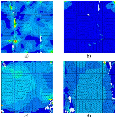
Due to the tensile loadings or combination tensile/compression or compression/tensile, the macrostructure of ceramic composite experiences intrinsic cracks when the computed stress exceeded the yield stress defined in the materials. Fig. 4 shows the stress concentrations present in the ceramic composite prior to fracture of the material.
a) b)
c) d)
Fig. 4 Fracture of the specimen at a) uniaxial, = 0°, b) pure tensile biaxial, 45°, c) combination tensile/compression, = 135°, and d) 315°.
Alumina
94%
Polymer S-2 glass
Along with the macrostructure deformation, the microcracks are easier to grow and coalesce under biaxial loading rather than uniaxial loading. Since the compression strength of ceramic is estimated 10 times larger than the tensile strength, there is no crack or damage can be observed at the zero strain rates. However, further increasing the strain rate at biaxial compression loadings may result to the microcracks.
5.2
Stress-strain curve
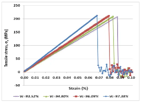
The stress responses of the RVE for both tensile and compression loading conditions are calculated to plot stress-strain curves. Fig. 5 shows the stress-strain curves for different volume fractions of ceramic. The catastrophic failure of the macrostructure is marked as the sudden drop of the stress level. Even though the ceramic composite is recognized as nonlinear, all macrostructures behave elastically until peak stress, which is followed by facture of specimen. Further fracture behaviour of specimen is display graphically by oscillating stress-strain curves. The peak stress is taken as the strength of the specimen and the principal stresses can be calculated in order to obtain the normal stress and the maximum shear stress.
Fig 5 Stress-strain curves with different volume fractions of ceramic.
At the volume fraction of ceramic varied between 90% and 99%, the macrostructures retain the similar stress strength. But increasing volume fraction of the reinforced polymer could produces stiffer ceramic composite layers because the strain strength is augmented,consequently lowering the Young’s modulus. Meanwhile, several studies [30,31,32] have found that microstructure does appear to play an important role in defining the mechanical properties. Each different configuration in microstructure was found to produce a different yield point and shaped curve, implying that configuration has an effect on the yielding behaviour of the RVE. However, different configurations of the ceramic in macrostructure level show unfavourable results in stress, indicating that the ceramic configuration, despite the uniformity and isotropic conditions, have very little effect on the strength response. Fig. 6 illustrates the
stress-strain curves for different configurations of ceramic in rectangular, diamond, hexagonal and mix-pellet forms. The stresses are almost similar to all ceramic configurations but each macrostructure produces different strain strength value.
Fig. 6 Stress-strain curves with different configurations of ceramic.
From the averaged stress in the boundary condition, the elastic properties of the ceramic composite are calculated using the solution of equations (14) and (15). The details and comparison with the empirical equation based on ceramic and polymer’s volume fractions, and the implicit analysis are shown in Table 2.
Table 2 Homogenous elastic properties
Properties Empirical Implicit Explicit
(GPa) 296 269 271
0.213 0.195 0.197
From the stress-strain curve for the uniaxial tensile loading, the Young’s modulus is estimated to be 295GPa which is closed to the empirical result. However, both estimations from the stress-strain curve and the empirical approach are reluctantly inconsistent because the Young’s modulus is estimated in representative of 1D element while the explicit method considering 2D stress values at x-direction and y-direction.
5.3
Effective yield stress surface
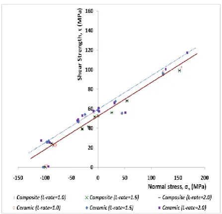
Fig. 7 Effective yield stress surface for ceramic composite and plain ceramic.
Considering the Mohr-Coulomb linear strength envelope, the plasticity and damage material properties of the ceramic composite are estimated as figured in Table 3. While apply the different loading rates to the RVE, the strain-rate function with associated dynamic increase factor on the failure properties can be defined as shown in Table 4 below.
Table 3 Plasticity properties of the homogenised ceramic composite material
Property Value
Stress cohesion, C 50.83MPa Friction angle, 35.64°
Dilation angle, 6°
Tensile strength, 210MPa Fracture energy, 121N/m
Table 4 Strain rate function of the homogenised ceramic composite material
(s-1) DIF (MPa)
1 1.20 252. 40
10 1.25 262.93
100 1.35 283.96
1000 1.70 357.58
6.
Conclusions
In the current study, the multi-scale analysis and numerical homogenisation were performed using the hybrid finite-discrete element method. In the numerical homogenisation, the constitutive law of ceramic composite layer was derived using a multi-scale analysis based on the periodic boundary displacement conditions. A suitable dynamic model of the ceramic composite layer was developed using the Modified Mohr-Coulomb
constitutive law where fracture in the model was governed explicitly by the Rankine and Rotating Crack criteria involve a transition from continuum to discontinuous elements. The results of stress-strain curves showed that the macrostructure configuration and volume fraction play an important role in affecting the mechanical properties of the RVE. However, it is necessary to identify the material properties using the 3D multi-scale analysis, therefore the constitutive law can be assigned as an anisotropic homogenous material.
References
[1] Nikl, T.R., Kobayashi, T., Oesterle, M. G., Lan, S., Morrill, K.B., Hegemier, G.A., and Seible, F. Carbon fiber composite jackets to protect reinforced concrete columns against blast damage. Proc. of Structures Congress, Texas, United States, (2009).
[2] Hoemann, J., Salim, H., and Dinan, R. Fiber reinforced polymer panels for blast and fragmentation mitigation. Proc. of the 78th Shock and Vibration Symposium, Philadelphia, United States, (2007).
[3] Yongxiang, D., Shunshan, F., Changjing, X., and Lele, G. Dynamic behaviour of concrete sandwich panel under blast loading. Journal Defence Science, Volume 59(1), (2009), pp. 22-29.
[4] Yu, S., Chenqing, W., and Mike, G. Mitigation of blast effects on aluminum foam protected masonry walls. Trans. Tianjin University, Volume 14, (2008), pp. 558-562.
[5] Ma, Z.D., Wang, H., Chui, Y., Rose, D., Sock, A., and Ostberg, D. Designing an innovative composite armor system for affordable ballistic protection. Proc. of the 25th Army Science Conference and Technology, Orlando, United States, (2006).
[6] Jiang, D., Liu, Y., Qi, C., Ma, Z.D., Raju, B., and Bryzik, W. Innovative composite structure design for blast protection. Proc. of the SAE World Congress, Michigan, United States, (2007).
[7] Nies, D.E., and McCaule, J.W. Advanced metals and ceramic for armor and anti-armor. High-fidelity design and processing of advanced armor. Technical Report Army Research Lab, Adelphi, United States, (2007).
[8] Lane, R., Craig, B., and Babcock, W. Material for Blast and penetration resistance. AMPTIAC, New York, United States, (2001).
[9] Krishnan, K., Sockalingam, S., Bansal, S., and Rajan, S.D. Numerical simulation of ceramic composite armor subjected to ballistic impact. Composite Engineering, Volume 41(8), 2010, pp. 583-593. [10]Speirs, D.C.D. Characterisation of materials with
hyperelastic microstructures through computational homogenisation and optimisation methods. Phd Thesis, Swansea University, United Kingdom, (2007).
Journal of the Mechanics and Physics of Solids, Volume 50, (2002), pp. 2123-2167.
[12]Terada, K., and Kikuchi, N. A class of general algorithms for multi-scale analysis of heterogeneous media. Computer Method in Applied Engineering, Volume 190, (2001), pp. 5427-5464.
[13]Ibrahimbegovic, A., and Markovic, D. Strong coupling methods in multi-phase and multi-scale modelling of inelastic behaviour of heterogeneous structures. Computer Method in Applied Engineering, Volume 192, (2003), pp. 3089-3107. [14]Terada, K., Matsui, K., and Yuge, K. Two-scale
finite element analysis of heterogeneous solids with periodic microstructures. Computers and Structures, Volume 82, (2004), pp. 593-606.
[15]Ohno, N., Wu, X., and Matsuda, T. Homogenized properties of elastic viscoplastic composites with periodic internal structures. International Journal of
Mechanical Sciences, Volume 42, (2000), pp. 1519-1536.
[16]Yang, Q.S., and Qin, Q.H. Modelling the effective elasto plastic properties of unidirectional composites reinforced by fibre bundles under transverse tension and shear loading. Materials Science and Engineering, Volume 344, (2003), pp. 140-145. [17]Buehler, M.J. Atomistic modelling of materials
failure. Springer, New York, United States, (2008). [18]Palencia, E.S. Boundary layers and edge effects in
composites, homogenisation technique for composite media. Springer, Berlin, Germany, (1987).
[19]Owen, D.R., Feng, Y.T., DeSauza Neto, E.A.M., Cotrell, G., Wang, F., Pires, F M.A., and Yu, J. The modelling of multi-fracture solids and particulate media. International Journal of Numerical Method in Engineering, Volume 60(1), (2004), 317-339. [20]Owen, D.R., and Feng, Y.T. Parallelised
finite/discrete element simulation of multi-fracturing solids and discrete systems. International Journal of Engineering Computations, Volume 18, (2001), pp. 557-576.
[21]Munjiza, A., Owen, D.R., and Bicanic, N.A.A Combined finite-discrete element method in transient dynamics of fracturing solids. International Journal of Engineering Computations, Volume 12, (1995), pp. 145-174
[22]Clausen, J.C., and Damkilde, L. A Simple and efficient fem implementation of the modified
Mohr-Coulomb criterion. Proc. of the 19th Nordic Seminar on Computational Mechanics, Lund, Sweden, (2006).
[23]Ottesen, N.S., and Ristinma, M. The mechanics of constitutive modelling. Elsevier, Oxford, UK, (2005).
[24]May, I.M., Chen, Y., Owen, D.R., and Feng, Y.T., and Bere, A.T. Experimental testing and finite element simulation of the behaviour of reinforced concrete beam under impact. Proc. of the 8th International Conference on Computational Plasticity, Barcelona, Spain, (2005).
[25]Klerck, P.A., Sellers, E.J., and Owen, D.R. Discrete fracture in quasi-brittle materials under compressive and tensile stress states. Computer Method in Applied Mechanics and Engineering, Volume 193, (2004), pp. 3035-3056.
[26]Klerck, P.A. The finite element modelling of discrete fracture in quasi-brittle materials. Phd Thesis, University of Wales, Swansea, United Kingdom, (2000).
[27]Munjiza, A. The combined finite discrete element method. Wiley, London, United Kingdom, (2004). [28]Munjiza, A., Latham, J.L., and Andrew, K.R.F.
Detonation gas model for combined finite-discrete element simulation of fracture and fragmentation. International Journal of Numerical Method in Engineering, Volume 49, (2000), pp. 1495-1520. [29]Cottrell, M.G. The development of rational
computational strategies for the numerical modelling of high velocity impact. Phd Thesis, University of Wales, Swansea, United Kingdom, (2002).
[30]Kouznetsova, V., Geers, M.G.D., and Brekelmans, W.A. Multi-scale constitutive modelling of heterogeneous materials with w gradient enhanced computational homogenization scheme. International Journal for Numerical Methods in Engineering, Volume 54, (2002), pp. 1235-1260.
[31]Zhou, F., and Molinari, J.F. Stochastic fracture of ceramic under dynamic tensile loading. International Journal of Solids and Structures, Volume 41, (2004), pp. 6573-6596.