Experimental Confinement Studies Beyond ITER
Akihide FUJISAWA
National Institute for Fusion Science, Oroshi-cho, Toki 509-5292, Japan
(Received 5 January 2009/Accepted 16 May 2009)
The advantages of stellarators are discussed with an emphasis on the high density limit more than 10 times higher than that of tokamaks with the equivalent magnetic field strength. The comparison between stellerators and tokamaks in the light of the new paradigm of plasma turbulence and zonal flows is presented to propose a new optimization principle of magnetic field configuration. The roles of low-temperature devices should be recognized for further understanding of the plasma confinement even in the era of burning state plasmas
c
2010 The Japan Society of Plasma Science and Nuclear Fusion Research
Keywords: tokamak, stellerator, density limit, zonal flow, flow damping, principle of configuration optimization, low temperature device
DOI: 10.1585/pfr.5.S1005
1. Introduction
The research aiming at realizing a sun on the earth has been carried out for more than fifty years. The efforts have advanced the physics of magnetically confinement along with the development of fusion technologies. A wide va-riety of the toroidal magnetic field confinement have been tested, such as tokamaks, spherical tokamaks, stellarators including many kinds of configurations (e.g., heliotron, he-liac, and helias), reversed field pinches, bumpy torii, mag-netic mirrors, and so on.
At present a device, ITER, is being constructed to real-ize a tokamak plasma in burning state. This is because the tokamak is the leading concept of the magnetically con-finement fusion, where a number of records, in fact, have been made. The followings have been achieved for in-stance; the ion temperature of 40 keV and the fusion prod-uct of 1.5×10²⁰ m−3·s·kev in JT-60U, the electron tem-perature of 20 keV in ADEX-U, the confinement time of 1.2 s and the stored energy of 17 MJ in JET. The spherical tokamak, with an extremely low aspect ratio of less than 2, has achieved the highestβof∼40%, together with high plasma confinement due to the large capacity of plasma current [1].
The studies of other magnetic configurations, how-ever, should still continue to be carried out to demonstrate their own advantages or individualities that can avoid the undesirable characteristics of standard tokamaks. For ex-ample, the nominal currentless characteristic of stellarators makes the steady state operation of the discharges much easier. The comparative studies of various concepts should be necessary to optimize magnetic field configuration in terms of confinement, energetic particle behaviour etc., and to realize an advantageous device adopting the merits of different concepts in terms of the economic and steady state operation. This paper will discuss several physical
author’s e-mail: [email protected]
and experimental topics for obtaining a better solution of a magnetically confined fusion device in future.
2. Advantages of Stellarators
2.1
High density operation of stellarators
The simple coil geometry of tokamak requires the in-ternal plasma current to produce rotational transform for the plasma confinement. The resultant confinement field has an axisymmetric nature to serve the good confinement property, however, the external current drive is mandatory for steady state operation. The toroidal current can be the cause of the disruption to determine the density limit, since the radiation density limit (or the Murakami limit [2]) should be too high to be met in the modern clean plasma with well-conditioned wall. The empirical formula to de-scribe the density limit of the modern tokamaks is known as the Hugil-Greenwald limit [3], which is expressed as¯
nG,limit(1020m−3)=
Ip
πa2 .
whereIp(MA) anda(m) represent the plasma current and the minor radius, respectively. It has been experimentally supported that the density limit in the tokamak plasma should be bounded by the violent deterioration of the con-finement [4].
On the other hand, the density limit of stellarators is known to be described by an empirical law, termed Sudo scaling [5, 6] which is approximately written as
¯
nS,limit(1020m−3)=0.25(PabsB/(aR2))0.5∝
PabsB.
whereR(m), Pabs(MW) and B(T) represent the major ra-dius, the absorbed power and the magnetic field, respec-tively. This expression suggests that the stellarator density limit should be deeply associated with the condition of ra-diation balance with the absorbed heating power, the
radi-c
2010 The Japan Society of Plasma
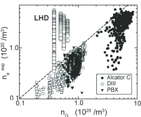
Fig. 1 Comparison between operational density in LHD and several tokamaks. The obtained density is plotted as the function of the corresponding Greenwald density. The achieved density in LHD is obviously ten times or much more higher than the Greenwald density (Courtesy of Prof. H. Yamada).
ation should be proportional to the square of density, i.e.,
Pabs∝n2e.
It has been also well known that the density limit of stellarators is well above the Greenwald limit. Figure 1 shows an example of the high density limit of the LHD heliotron, compared to the Greenwald limit of tokamaks. Moreover, the stellarators do not show any violent plasma behavior around the density limit, while the tokamak oper-ation near the density limit leads the plasma to disruptions.
2.2
Behavior near density limit in
stellara-tors
A number of scenarios have been reported for stel-larator plasmas around the density limit. In addition to the behavior like apparent radiation collapses, the rapid decrease in the stored energy and the following recovery, calledbreathing, is found around the density limit of the NBI plasmas in LHD [7] and W7-AS [8], when the mag-netic field strength is properly selected at a fixed heating power.
In CHS an interesting behavior suggesting a transition is observed at the density limit. Figure 2 shows the tempo-ral evolutions of line-averaged density, radial power, stored energy, and so on. The plasma is sustained with elec-tron cycloelec-tron resonance (ECR) heating with rather low power of∼100 kW. In this case the line-averaged density increases gradually to reach a density limit. At the begin-ning of the exponential growth of radiation, a concomitant decrease with the stored energy is observed without any significant increase in MHD activities in a Mirnov coil sig-nal. Just after the radiation reaches its maximum, the rapid decrease of radiation occurs and the radiation relaxes into a constant value. The potential signal observed with an
Fig. 2 Behavior of the ECR-heated CHS plasma at∼100 kW. Time evolutions of (a) line-averaged density, stored en-ergy,(b) radiation, magnetic field fluctuation power less than 50 kHz, (c) potential, and density fluctuations mea-sured with HIBPs. The density limit is achieved or a tran-sition happens att90 ms.
HIBP also shows a rapid decrease in potential simultane-ously with the radiation.
According to the observation, the plasma behavior be-fore and after the density limit (or maixmum) point can be regarded as a transition from a state with high stored en-ergy (or temperature) to the other one with extremely low stored energy (or temperature). On the other hand, the den-sity fluctuations observed with an HIBP, or intermittent ac-tivity of density, show a rise and fall to increase during this transition. This observation suggests that turbulent trans-port could play an imtrans-portant role in the plasma behavior around the density limit. The magnetic field dependence in the Sudo scaling should suggest the relation between the turbulent transport and density limit, i.e.,nlimit∝
√
B.
2.3
Attractive confinement regimes in
stell-rators
Recent studies in stellarators have found many inter-esting operational regimes, such as super dense core (SDC) in LHD [9, 10]. In the SDC discharge, the achieved den-sity is 4.5×10²⁰m−3 with electron temperature of 0.85 keV. This is attained with a series of pellet injections. Be-sides, the high density H (HDH) mode was found in W7-AS [11–13] where the density up to 4×10²⁰m−3 is sus-tained in a rather stationary manner.
move-Fig. 3 HDH mode discovered in W7-AS. (a) The comparison between density and temperature profiles in normal con-finement (NC) and improved concon-finement (HDH) mode. (b) The difference between confinement times of NC and HDH mode. The squares indicate the impurity confine-ment time.
ment of carbon is observed when high toroidal rotation of plasma is induced by higher power of neutral beam injec-tion (NBI) [14]. This feature is an advantage because spon-taneous ash-removal can be expected if this phenomenon is valid for helium ions.
3. Transport and New Paradigm
3.1
Collisional transport and symmetry
The transport in magnetically confinement plasma is described as the total of collisional and turbulent transport. The diffusive coefficient of collisional process is generally expressed asD ∝Δ2νei, whereΔandνeiare the effective step width and collision frequency, respectively. The eff ec-tive step width is related with the deviation of a particle or-bit from the magnetic field flux surface, and can be large if the collisionality is sufficiently low to allow the particles to be trapped in the magnetic field mirror associated with the inhomogeneity of the confinement magnetic field. There-fore, the effective step width is a function of collisionality and geometrical property of confinement field.
In tokamaks, the poloidal inhomogeneity of the mag-netic configuration gives birth to the particles trapped in poloidal mirror field, termed banana particles. The exis-tence of banana particles enhances the collisional trans-port. On the other hand, non-axisymmetric (or three di-mensional) configurations of stellarators produce the other kind of trapped particles, so-called helically trapped par-ticles, to enhance the collisional transport. Therefore, the superiority of stellarators in steady state operation can be accompanied with the inferiority in collisional transport without any optimization of the magnetic field configura-tion [15].
3.2
Bipolar di
ff
fusion and barrier formation
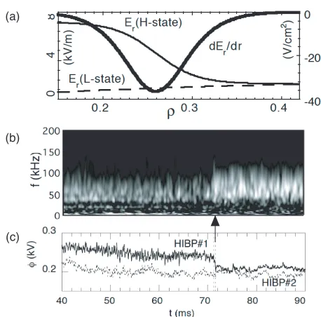
Confinement improvement, in addition to steady state operation, is a critical issue in order to realize a more eco-nomic reactor. The stellarators could provide a compatibleFig. 4 The property of transport barrier in stellarator. (a) The profiles of radial electric field and its shear around the ITB in CHS. (b) Electric field fluctuations at the barrier before and after the collapse of the barrier, and (c) poten-tial drop inside the barrier indicating the collapse of the barrier, together with the potential outside.
solution to realize the improvement of turbulence driven transport and steady state operation. It is known that the bipolar diffusion due to helically trapped particles should be the dominant process to form the radial electric field in stellarators. The radial electric field in a steady state should be determined by the balance between collisional ion and electron fluxes denotedΓion(Er) andΓelectron(Er), respectively, i.e.,Γion(Er)−Γelectron(Er)=0 in stellarators, while the generation mechanism of radial electric field is still an open question in tokamaks. Moreover, the nonlin-ear dependence of collisional fluxes on radial electric field causes the bifurcation nature of radial electric field in stel-larators [16, 17].
This bifurcation nature of radial electric field with stellarators has been found to be the cause of internal transport barrier (ITB) commonly observed in stellara-tors [18–21]. The formation scenario is identical with the model proposed for the explanation of H-mode initially [22, 23]. In a stellarator plasma core where temperature is above a critical value, the radial electric field makes a transition into a strongly positive branch (or electron root) with the radial electric field outside still remaining in a weakly positive branch (or ion root). As is shown in Fig. 4(a), the transition creates the transient layer between the two branches. The rather large electric field shear is produced in the layer to reduce the turbulence and form the transport barrier according to the E×B-shearing of turbulence [24–28].
layer or the position of the ITB after the back-transition in-dicated by the sudden drop of potential (Fig. 4 (c)). The ob-served transition time scale of radial electric field is in the range of a few dozen microseconds, being consistent with that prediction of the neoclassical theory [29], The time scale is much faster than the confinement time scale, there-fore, this means that the existence of multi-steady states of electric field.
Accordingly, the ITB in stellarators is an exception-ally clear example to demonstrate that the electric field bi-furcation can be the cause for the barrier formation. In contrast the formation of the H-mode or edge transport bar-riers both in tokamaks and stellarators still allows of many candidate mechanisms; some experimental results suggest the balance between fast ion loss and parallel viscosity, while some others suggest the turbulent Reynolds stress should play an important role. The non-axisymmetric fea-ture, instead of the anxiety of collisional transport, could give stellarators an advantage in the transport barrier for-mation, of which cause is clearly identified thus theoreti-cally predictable rather easily.
3.3
Zonal flows and new paradigm
The magnetic well and shear have been known to be the concepts to measure the magnetic configuration prop-erty to stabilize the linear MHD and drift wave instabilities. Therefore, these concepts have been used as the major fac-tors to optimize the magnetic field configuration. The re-cent development of theories and plasma diagnostics also has shown a new paradigm [30, 31], which could be com-mon for magnetically confined plasmas, to understand the saturation mechanisms of the plasma turbulence and the re-sultant transport. In other words, the new paradigm can be a new factor to evaluate the property of the magnetic field configuration in terms of turbulent saturation mechanism, while the magnetic shear and well serves as the factors to
Fig. 5 The identified radial pattern of zonal flows in CHS. The radial structure of zonal flows is represented in the radial correlation function.
assess the linear growth of the instabilities [32, 33]. In the new paradigm, the turbulence should be recog-nized as a system of zonal flows and drift waves. Inho-mogeneity of plasma (i.e., temperature and density gra-dients) causes drift wave turbulence to result in the en-hancement of plasma transport. Then the drift waves gen-erate and transfer the energy to zonal flows through the
v∇v-nonlinearity. Moreover, the zonal flows give back-reactions on the drift waves, such asE×B-shearing, wave trappings, and so on, to work as further reduction of drift-waves. The symmetric nature of zonal flows causes no ra-dial or cross-field transport. Therefore, the increase in the zonal flow fraction in the turbulence contributes to lessen the anomalous transport. The fraction of zonal flows in the power spectrum of electric field fluctuations, therefore, is a key to determine the turbulent transport level.
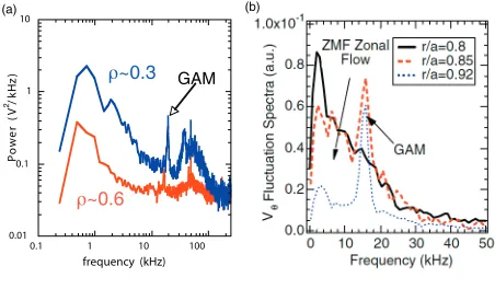
The direct measurements of electric field fluctuations in CHS have proven the existence of zonal flows experi-mentally, together with the couplings between zonal flows and the background turbulence [34–36]. A number of perimental reports have been accumulated to show the ex-istence of Geodesic Acoustic Modes (GAMs), an oscilla-tory branch of zonal flows [31], and their couplings with the background turbulence [37] using direct and indirect measurements of flow or electric field. Therefore, the new paradigm of plasma turbulence and transport is widely pre-vailed nowadays. Figure 5 shows the radial correlation function between the electric field fluctuations correspond-ing to the stationary zonal flows, visualizcorrespond-ing the radial pat-tern of zonal flows.
3.4
Confinement and flow damping rate
The essential requirement for detecting the zonal flows is to measure the fluctuations of plasma flows or elec-tric field directly. This imposes a quite difficult constraint on the present plasma diagnostics, therefore, limited data have been available. However, the comparison between fluctuation spectra of flow (or electric field) in tokamak and stellarator is possible. Figure 6 shows the electric field spectra directly measured with HIBPs in the core of CHSstellarator, and the flow fluctuation spectra indirectly mea-sured with BES in the edge region of DIII-D tokamak [38]. In spite of the difference of magnetic field configura-tion and the observed locaconfigura-tions, the comparison shows the common features, i) a region corresponding to stationary zonal flows exists, ii) the oscillatory branches, GAMs, are observed as sharp peaks, and iii) regions with broad band fluctuations corresponding to drift waves with a higher frequency from a few dozen kHz to a hundred kHz are present. In the case of CHS stellarator, the fraction of turbulent power increases being accompanied with the in-crease of zonal flow fraction to that of the drift waves around∼50 kHz, probably due to the enhancement of tem-perature gradient in the plasma core region. In the case of DIII-D tokamak, the GAM fraction decreases with an increase in zonal flow amplitude as the observation point goes inward.
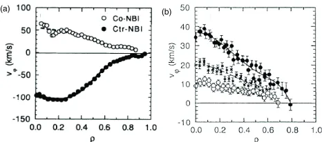
It has been found that the absolute value of GAM am-plitude should be much larger in tokamak that in stellara-tor. The HIBP observations in JIPPT-IIU [39] showed that the GAM potential amplitude can exceed∼ 100 V, while that in CHS stellarator should be in the range of a few volts. This may be ascribed to the larger parallel viscos-ity of stellarators. Figure 7 shows the comparison between toroidal flows driven by NBI in stellarator (CHS) and toka-mak (JFT-2 M). Obviously, the resultant toroidal rotation velocity in tokamak is much faster than that in stellarator, although the input NBI power is in the same range in both experiments of CHS [40] and JFT-2 M [41]. Thus, the in-homogeneity should give a large damping effect on plasma flows.
As for the ITB in stellarator, the transport inside the barrier is also found to be improved without any signifi-cant electric field shear. Recently, it has been confirmed in CHS that this improvement is caused by the enhancement of zonal flow fraction, as is shown in Fig. 8, due to the re-duction of flow damping rate [42, 43]. The zonal flows (or zonal radial electric field) are driven by turbulence, there-fore, the turbulent radial current to drive the zonal flows,
δjturb, should be balanced with the neoclassical radial cur-rent (or total radial flux of ions and electrons) in stellara-tors, this condition is expressed asδjturb+(∂jneo/∂Er)δEr = 0, where (∂jneo/∂Er) could be called the effective neoclas-sical viscosity. The low effective viscosity in electron root is experimentally confirmed, as is shown in the inset of Fig. 8, in addition to the prediction by neoclassical colli-sional transport theories.
These facts suggest that the zonal flow fraction should be large as the flow-damping rate is low. Hence, the mag-netic field configuration with lower parallel viscosity or magnetic inhomogeneity should give a better confinement owing to the possible enhancement of zonal flow fraction. The new paradigm could provide an optimization principle for the magnetic field configuration in the light of turbu-lence transport by its saturation mechanism.
Fig. 7 The comparison between induced toroidal flows in toka-mak (JFT-2 M) and stellarator (CHS). (a) The profile of toroidal flow velocity in JFT-2 M and (b) that in CHS. The toroidal flows are measured with charge exchange recombination spectroscopy.
Fig. 8 The fluctuation power of drift waves as a function of that of zonal flows for the state with and without confinement improvement in CHS. The measurement was carried out at a point inside the position of ITB. The increase in zonal flow power should be ascribed to the decrease in effective viscosity accompanied with the transition from ion (point B) into electron root (point A). The effective viscosity corresponds to the slope of the tangential lines at the sta-ble points of radial electric field in the inset. It is clear that the slope of ion root is steeper than that of electron root solution.
4. Beyond Simple Comparison
4.1
Roles of low temperature devices
High accessibility and flexibility must be of essen-tial need for the experiments aiming at finding the phys-ical laws underlying the structural formation of plasmas. The role of low temperature devices should be emphasized in addition to exploring new possible diagnostics for high temperature plasmas. Low temperature devices, even a lin-ear cylindrical device, provide good environments to study the fundamental processes of plasma turbulence and trans-port.
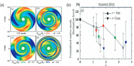
confine-Fig. 9 Observation to demonstrate the interplay between the sheared flows and a pressure driven mode in a linear cylindrical plasma. The sheared flow strength is con-trolled by the degree of the modulation of ECR-heating. (a) The reconstructed images of the interplay between sheared flows and the mode. (b) The suppression degree as a function of a parameter to indicate the shear flow strength,α.
ment [46]. The simultaneous measurements of both radial and poloidal wavenumbers using 2-dimensional probes in TJ-K succeeded in clarifying the fundamental process of magnetized plasma turbulence, i.e., the nature of dual cas-cade in a two dimensional flow system [47].
Besides, a number of excellent experimental results have been reported from cylindrical linear devices in uni-versity laboratories. In CSDX, a cylindrical laboratory plasma, the momentum balance between the turbulent Reynolds stress drive and viscous damping was inves-tigated and successfully demonstrated that the turbulent Reynolds stress should be the cause of the zonal flow generation [48]. In a cylindrical machine, LMD-U, the streamer formation has been identified with an efficient use of the combination of 64 channel azimuthal probe array and 2 dimensionally movable probes [49].
Recently, In a laboratory cylindrical plasma of Kyushu university, the detailed processes of sheared flow effect were observed in externally induced sheared flow using the modulation of the plasma heating power [50]. In the device, a pressure-driven instability is observed in electron cyclotron heated plasma as a sharp peak without any modulation of heating. By applying the ECR-heating modulation, the sheared flows are induced to inter-act with and suppress the native mode. Figure 9 shows the images of the change of the reconstructed potential fluc-tuation patterns according to the modulation intensity of heating power, and the suppression ratio of the native mode as a function of the strength of the induced sheared flow. The results clearly demonstrate how the native mode is al-tered as the shear flow becomes stronger, suggesting that the process of three wave coupling should play a role in the suppression.
4.2
Concluding remarks
Tokamak is the leading concept for fusion reactor, however, it is necessary to overcome a number of issues for
realizing an economically compatible reactor. The advan-tageous properties of the other toroidal devices, therefore, should be incorporated into a Demo and following reac-tors; for instance, the advantage with stellarators, the high density operation exceeding the Greenwald limit without any disruptive activities, would be desired to be adopted to the tokamak concept even though the axisymmetric na-ture giving a good plasma confinement may be partially destroyed. In order to realize a device with a combined concept or an optimizing configuration, it is absolutely es-sential to understand the plasma behavior to determine the operational boundaries and the plasma confinement from the first principle, which should result in the precise and ac-curate prediction of magnetically confined plasma perfor-mance to any given configurations. Therefore, the impor-tant roles of medium and small sized devices oriented for physical understanding of toroidal plasmas are strengthen even in the era of burning plamsas.
[1] M. Gryaznevichet al., Phys. Rev. Lett.80, 3972 (1998). [2] M. Murakamiet al., Nucl. Fusion16, 347 (1976). [3] M. Greenwaldet al., Nucl. Fusion28, 2199 (1988). [4] D.L. Broweret al., Phys. Rev. Lett.67, 200 (1991). [5] S. Sudoet al., Nucl. Fusion30, 11 (1990).
[6] J. Miyazawaet al., Nucl. Fusion48, 015003 (2008). [7] B.J. Petersonet al., Nucl. Fusion41, 519 (2001).
[8] L. Giannoneet al., Plasma Phys. Control. Fusion42, 603 (2000).
[9] N. Ohyabuet al., Phys. Rev. Lett.97, 055002 (2006). [10] R. Sakamotoet al., Nucl. Fusion46, 884 (2006). [11] K. McCormicket al., Phys. Rev. Lett.89, 015001 (2002). [12] F. Wagneret al., Plasma Phys. Control. Fusion48, A217
(2006).
[13] M. Hirschet al., Plasma Phys. Control. Fusion50, 053001 (2008).
[14] K. Ida, M. Yoshinuma, M. Osakabeet al., Phys. Plasmas 16, 056111 (2009).
[15] H.E. Mynick, Phys. Plasmas13, 058102 (2006). [16] L.M. Kovrizhnykh, Nucl. Fusion24, 435 (1984). [17] D.E. Hastings, Phys. Fluids27, 935 (1984). [18] A. Fujisawaet al., Phys. Rev. Lett.82, 2669 (1999). [19] U. Strothet al., Phys. Rev. Lett.86, 5910 (2001). [20] A. Fujisawa, Plasma Phys. Control. Fusion45, R1 (2003). [21] M. Yokoyamaet al., Nucl. Fusion47, 1213 (2007). [22] S.-I. Itoh and K. Itoh, Phys. Rev. Lett.60, 2276 (1988). [23] K.C. Shaing and E.C. Crume Jr., Phys. Rev. Lett.63, 2369
(1989).
[24] K.C. Shainget al.,Proceedings of 12th International Con-ference on Plasma Physics and Controlled Nuclear
Fu-sion Research, Nice, 1988 (International Atomic Energy
Agency, Vienna, 1989) Vol.2, p.13. [25] H. Biglariet al., Phys. Fluids B2, 1 (1990).
[26] K. Itohet al., Plasma Phys. Control. Fusion36, 123 (1994). [27] T.S. Hahm and K.H. Burrel, Phys. Plasmas2, 1648 (1995). [28] Z. Linet al., Science281, 1835 (1998).
[29] A. Fujisawaet al., Phys. Rev. Lett.79, 1054 (1997). [30] P. H. Diamondet al., Plasma Phys. Control. Fusion47, R35
(2005).
[34] A. Fujisawaet al., Phys. Rev. Lett.93, 165002 (2004). [35] A. Fujisawaet al., Plasma Phys. Control. Fusion49, 211
(2007).
[36] A. Fujisawaet al., J. Phys. Soc. Jpn.76, 033501 (2007). [37] Y. Nagashimaet al., Phys. Rev. Lett.95, 095002 (2005). [38] D.K. Guptaet al., Phys. Rev. Lett.97, 125002 (2006). [39] Y. Hamadaet al., Nucl. Fusion45, 81 (2005). [40] K. Idaet al., Phys. Rev. Lett.67, 58 (1991). [41] K. Idaet al., Phys. Rev. Lett.68, 182 (1992). [42] K. Itohet al., Phys. Plasmas14, 020702 (2007). [43] A. Fujisawaet al., Phys. Plasmas15, 055906 (2008).
[44] M.G. Shatset al., Phys. Rev. E71, 046409 (2005). [45] H. Xia, M.G. Shats and H. Punzman, Phys. Rev. Lett.97,
255003 (2006).
[46] U. Strothet al., Phys. Plasma11, 2558 (2004).
[47] P. Manzet al., Plasma Phys. Control. Fusion50, 035008 (2008).
[48] G.R. Tynanet al., Plasma Phys. Control. Fusion48, S51 (2006).
[49] T. Yamadaet al., Nature Phys.4, 721 (2008).