An Improved IUPQC Controller to Provide
Additional Grid-Voltage Regulation with fuzzy logic
controller
Sk Saheenabi
1, Shaik Dawood
21
M.Tech(PS) Nimra Institute of Science and Technology, Vijayawada, AP
2
Asst Professor Dept of EEE, Nimra Institute of Science and Technology, Vijayawada, AP
Abstract
This paper presents an improved controller for the dual topology of the unified power quality conditioner (iUPQC) extending its applicability in power-quality compensation, as well as in micro grid applications. By using this controller, beyond the conventional UPQC power quality features, including voltage sag/swell compensation, the iUPQC will also provide reactive power support to regulate not only the load-bus voltage but also the voltage at the grid-side bus. In other words, the iUPQC will work as a static synchronous compensator (STATCOM) at the grid side, while providing also the conventional UPQC compensations at the load or micro grid side here the controlling is used in fuzzy logic controller.
I. INTRODUCTION
CERTAINLY, power-electronics devices
have brought about great technological improvements. However, the increasing number of power-electronics-driven loads used generally in the industry has brought about uncommon power quality problems. In contrast, power-electronics-driven loads generally require ideal sinusoidal supply voltage in order to function properly, whereas they are the most responsible ones for abnormal harmonic currents level in the distribution system. In this scenario,
devices that can mitigate these drawbacks have been developed over the years. Some of the solutions involve a flexible compensator, known as the unified power quality conditioner (UPQC) and the static synchronous compensator (STATCOM) The power circuit of a UPQC consists of a combination of a shunt active filter and a series active filter connected in a back-to-back configuration. This combination allows the simultaneous compensation of the load current and the supply voltage, so that the compensated current drawn from the grid and the compensated supply voltage delivered to the load are kept
balanced and sinusoidal. The dual
topology of the UPQC,i.e., the iUPQC, where the shunt active filter behaves as an ac-voltage source and the series one as an ac-current source, both at the fundamental frequency. This is a key point to better design the control gains, as well as to
optimize the LCL filter of the power
converters, which allows improving
particular cases, where their relatively high costs are justified by the power quality improvement it can provide, which would be unfeasible by using conventional
solutions. By joining the extra
functionality like a STATCOM in the iUPQC device, a wider scenario of applications can be reached, particularly in case of distributed generation in smart grids and as the coupling device in grid-tied micro grids. The performance of the iUPQC and the UPQC was compared when working as UPQCs. The main difference between these compensators is the sort of source emulated by the series and shunt power converters. In the UPQC approach, the series converter is controlled as a non-sinusoidal voltage source and the shunt one as a non-sinusoidal current source. Hence, in real time, the UPQC controller has to determine and synthesize accurately the harmonic voltage and current to be compensated. On the other hand, in the iUPQC approach, the series
converter behaves as a controlled
sinusoidal current source and the shunt converter as a controlled sinusoidal voltage source. This means that it is not necessary to determine the harmonic voltage and current to be compensated, since the harmonic voltages appear naturally across the series current source and the harmonic currents flow naturally into the shunt voltage source. In actual power converters, as the switching frequency increases, the power rate capability is reduced. Therefore, the iUPQC offers better solutions if compared with the UPQC in case of high-power
applications, since the iUPQC
compensating references are pure
sinusoidal waveforms at the fundamental frequency. Moreover, the UPQC has higher switching losses due to its higher switching frequency.
Fig1 : simulation circuit
This paper proposes an improved
controller, which expands the iUPQC functionalities. This improved version of
iUPQC controller includes all
functionalities of those previous ones, including the voltage regulation at the load-side bus, and now providing also voltage regulation at the grid-side bus, like a STATCOM to the grid. Experimental results are provided to validate the new controller design.
II. EQUIPMENT PLICABILITY
harmonics, unbalance, and sag/swell. Nevertheless, this is still not enough to guarantee the voltage regulation at bus A. Hence, to achieve all the desired goals, a STATCOM at bus A and a UPQC (or an iUPQC) between buses A and B should be employed. However, the costs of this solution would be unreasonably high. An attractive solution would be the use of a modified iUPQC controller to provide also reactive power support to bus A, in addition to all those functionalities of this equipment. Note that the, modified iUPQC serves, as an intertie between buses A and B. Moreover, the micro grid, connected to the bus B could be a complex system comprising distributed generation, energy
management system, and other
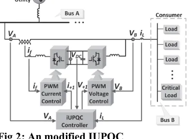
Fig 2: An modified IUPQC
control systems involving microgrid, as well as smart grid. In summary, the modified iUPQC can provide the following functionalities:
a) “smart” circuit breaker as an intertie between the grid and the microgrid;
b) energy and power flow control between the grid and the microgrid (imposed by a tertiary control layer for the microgrid); c) reactive power support at bus A of the power system;
d) voltage/frequency support at bus B of the microgrid;
e) harmonic voltage and current isolation between bus A and bus B (simultaneous
grid-voltage and load-current
activefilteringcapability);
f) voltage and current imbalance
compensation.
Fig. 2 depicts,in detail, the connections and measurements of the iUPQC between bus A and bus B. According to the conventional iUPQC controller, the shunt converter imposes a controlled sinusoidal voltage at bus B, which corresponds to the aforementioned functionality (d). As a result, the shunt converter has no further
degree of freedom in terms of
compensating active- or reactive-power variables to expand its functionality. On the other hand, the series converter of a conventional iUPQC uses only an
active-power control variable p, in order to
synthesize a fundamental sinusoidal
current drawn from bus A, corresponding to the active power demanded by bus B. If the dc link of the iUPQC has no large energy storage system or even no energy
source, the control variable p also serves
as an additional active-power reference to the series converter to keep the energy inside the dc link of the iUPQC balanced. In this case, the losses in the iUPQC and the active power supplied by the shunt converter must be quickly compensated in the form of an additional active power injected by the series converter into the bus
B. The iUPQC can serve as
a) “smart” circuit breaker and as
b) power flow controller between the grid
and the micro grid only if the
compensating active- and reactive-power references.
III. IMPROVED IUPQC
CONTROLLER
A. Main Controller
A and B, the current demanded by bus B
(iL), and the voltage vDC of the common
dc link. The outputs are the shunt-voltage reference and the series-current reference to the pulsewidth modulation (PWM) controllers. The voltage and current PWM controllers can be as simple as those employed in or be improved further to better deal with voltage and current imbalance and harmonics. First, the simplified Clark transformation is applied to the measured variables. As example of this transformation, the grid voltage in the αβ-reference frame can be calculated as
The shunt converter imposes the voltage at bus B. Thus, it is necessary to synthesize
sinusoidal voltages with nominal
amplitude and frequency. Consequently, the signals sent to the PWM controller are the phase-locked loop (PLL) outputs with amplitude equal to 1 p.u. There are many possible PLL algorithms. In the original iUPQC approach as presented in [14], the shunt-converter voltage reference can be either the PLL outputs or the fundamental
positive-sequence component VA+1 of the
grid voltage (bus A in Fig. 2). The use of VA+1 in the controller is useful to minimize the circulating power through the series and shunt converters, under normal operation, while the amplitude of the grid voltage is within an acceptable range of magnitude. However, this is not the case here, in the modified iUPQC controller, since now the grid voltage will be also regulated by the modified iUPQC. In other words, both buses will be regulated independently to track their reference values.The series converter synthesizes the current drawn from the grid bus (bus A). In the original approach of iUPQC, this current is calculated through the average active power required by the loads PL plus the power PLoss. The load active power can be estimated by
where iL_α, iL_β are the load currents, and
V+1_α, V+1_β are the voltage references
for the shunt converter. A low-pass filter is used to obtain the average active power (PL). The losses in the power converters and the circulating power to provide energy balance inside the iUPQC are
calculated indirectly from the
measurement of the dc-link voltage. In
other words, the power signal PLoss is
determined by a proportional– integral (PI) controller by comparing the measured dc
voltage VDC with its reference value. The
additional control loop to provide voltage regulation like a STATCOM at the grid bus is represented by the control signal QSTATCOM. This control signal is obtained through a PI controller, in which the input variable is the error between the reference value and the actual aggregate voltage of the grid bus, given by
The sum of the power signals PL and
PLoss composes the active-power control variable for the series converter of the iUPQC (p) described in Section II.
Likewise, QSTATCOM is the
reactive-power control variable q. Thus, the current
references i+1α and i+1β of the series
converter are determined by
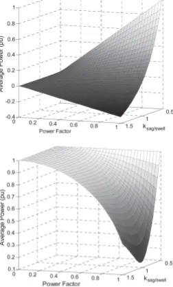
Fig. 3 depicts the apparent power of the series and shunt power converters. In these figures, the ksag/swell-axis and the PF-axis are used to evaluate the power flow in the series and shunt power converters
according to the sag/swell voltage
disturbance and the load power
power converters are necessary to ensure the disturbance compensation. Moreover, in case of compensating sag/swell voltage disturbance with high reactive power load consumption, only the shunt converter has
high power demand, since Pinner
decreases. It is important to highlight that, for each PF value, the amplitude of the apparent power is the same for capacitive or inductive loads. In other words, Fig. 5 is the same for QB capacitive or inductive. If the iUPQC performs all original UPQC
functionalities together with the
STATCOM functionality, the voltage at bus A is also regulated with the same phase and magnitude, that is, V˙ A = V˙ B = V˙ N, and then, the positive sequence the
Fig 3:Apparent power of the series and
shunt converters, respectively.
IV. EXPERIMENTAL RESULTS
The improved iUPQC controller, as shown in Fig. 3, was verified in a 5-kVA
prototype, whose parameters are
presented. The controller was embedded in a fixed-point digital signal processor (TMS320F2812). In order to verify all the power quality issues described in
this paper, the iUPQC was connected to a grid with a voltage sag system, as depicted in Fig. 4. The voltage sag system was
composed by an inductor (LS), a resistor (RrmSag), and a breaker (SSag). To cause a voltage sag at bus A, SSag is closed. At first, the source voltage regulation was tested with no load connected to bus B. In this case, the iUPQC behaves as a
STATCOM,and the breaker SSag is closed
to cause the voltage sag.
Fig 4:simulation circuit
Fig 5:sub system
To verify the grid-voltage regulation (see
Fig. 7), the control of the QSTATCOM
variable is enabled to compose (4) at
instant t = 0 s. In this experimental case,
LS = 10 mH,and RSag =7.5 Ω. Before the
A, as shown in Fig. 6. After t = 0s, the iUPQC starts to draw reactive current from bus A, increasing the voltage until its reference value. As shown in Fig. 6, the load voltage at bus B is maintained regulated during all the time, and the grid-voltage regulation of bus A has a fast response.
Fig. 7. iUPQC response at no load condition:
(a) grid voltages VA, (b) load voltages VB, and (c) grid currents
Fig. 8. iUPQC transitory response during the connection of a threephase diode rectifier: (a) load currents, (b) grid currents, (c) loadvoltages and (d) grid voltages
Next, the experimental case was carried out to verify the iUPQC performance during the connection of a nonlinear load with the iUPQC already in operation. The load is a three phase diode rectifier with a
series RL load at the dc link(R = 45 Ω and
L = 22 mH), and the circuit breaker SSag
ispermanently closed, with a LS = 10 mH
and a RSag = 15 Ω. In this way, the
voltage-sag disturbance is increased due to the load connection. In Fig. 8, it is possible to verify that the iUPQC is able to regulate the voltages at both sides of the iUPQC, simultaneously. Even after the load connection, at t = 0 s, the voltages are still regulated, and the currents drawn from bus
Fig. 9.iUPQC transitory response during the connection of a twophase diode rectifier: (a) load currents, (b) source currents, (c) load voltages, and (c) source voltages
Finally, the same procedure was
performed with the connection of a two-phase diode rectifier, in order to better verify the mitigation of power quality issues. The diode rectifier has the same dc
load (R = 45 Ω and L = 22 mH) and the
same voltage sag (LS = 10 mH and
transitory response of the load connection. Despite the twophase load currents, after
the load connection at t = 0 s, the
three-phase current drained from the grid has a reduced unbalanced component. Likewise, the unbalance in the voltage at bus A is negligible. Unfortunately, the voltage at bus B has higher unbalance content. These components could be mitigated if the shunt compensator works as an ideal voltage source, i.e., if the filter inductor could be eliminated. In this case, the unbalanced current of the load could be supplied by the shunt converter, and the voltage at the bus B could be exactly the voltage synthesized by the shunt converter. Therefore, without filter inductor, there would be no unbalance voltage drop in it and the voltage at bus B would remain balanced. However, in a practical case, this inductor cannot be eliminated, and an improved PWM control to compensate voltage unbalances, as mentioned in Section III, is necessary.
V. CONCLUSION
In the improved iUPQC controller, the
currents synthesized by the series
converter are determined by the average active power of the load and the active power to provide the dc-link voltage regulation, together with an average reactive power to regulate the grid-bus voltage. In this manner, in addition to all the power-quality compensation features of a conventional UPQC or an iUPQC, this
improved controller also mimics a
STATCOM to the grid bus. This new feature enhances the applicability of the iUPQC and provides new solutions in future scenarios involving smart grids and
microgrids, including distributed
generation and energy storage systems to better deal with the inherent variability of renewable resources such as solar and wind power. Moreover, the improved iUPQC controller may justify the costs and promotes the iUPQC applicability in
power quality issues of critical systems, where it is necessary not only an iUPQC or a STATCOM, but both, simultaneously. Despite the addition of one more power-quality compensation feature, the grid-voltage regulation reduces the inner-loop circulating power inside the iUPQC, which would allow lower power rating for the series converter. The experimental results verified the improved iUPQC goals. The grid-voltage regulation was achieved with no load, as well as when supplying a three-phase nonlinear load. These results
have demonstrated a suitable performance of voltage regulation at both sides of the
iUPQC, even while compensating
harmonic current and voltage imbalances.
REFERENCES
[1] K. Karanki, G. Geddada, M. K. Mishra, and B. K. Kumar, “A modified three-phase four-wire UPQC topology with reduced DC-link voltage rating,” IEEE Trans. Ind. Electron., vol. 60, no. 9, pp. 3555–3566, Sep. 2013.
[2] V. Khadkikar and A. Chandra, “A new control philosophy for a unified power quality conditioner (UPQC) to coordinate load-reactive power demand between
shunt and series inverters,” IEEE Trans.
Power Del.,
vol. 23, no. 4, pp. 2522–2534, Oct. 2008. [3] K. H. Kwan, P. L. So, and Y. C. Chu, “An output regulation-based unified power quality conditioner with Kalman filters,” IEEE Trans. Ind. Electron., vol. 59, no. 11, pp. 4248–4262, Nov. 2012.
[4] A. Mokhtatpour and H. A. Shayanfar, “Power quality compensation as well as power flow control using of unified power
quality conditioner,” in Proc. APPEEC,
2011, pp. 1–4.
[5] J. A. Munoz et al., “Design of a
discrete-time linear control strategy for a
multicell UPQC,” IEEE Trans. Ind.
[6] V. Khadkikar and A. Chandra,
“UPQC-S: A novel concept of
simultaneous voltage sag/swell and load reactive power compensations utilizing
series inverter of UPQC,” IEEE Trans.
Power Electron., vol. 26, no. 9, pp. 2414– 2425, Sep. 2011.
[7] V. Khadkikar, “Enhancing electric
power quality using UPQC: A
comprehensive overview,” IEEE Trans.