Author for correspondence:
1Student, Department of Mechanical Engg (CAD/CAM), Holy Mary Institute Technology and Science, Hyderabad, Telangana, India
Volume-5 Issue-4
International Journal of Intellectual Advancements
and Research in Engineering Computations
Structural and dynamic analysis of crack propagation in composite
material
Kommu Parsharamulu
1, Malsoor
2, Pedamuthevi Vijayanand
31
Student, Department of Mechanical Engg (CAD/CAM), Holy Mary Institute Technology and Science,
Hyderabad, Telangana, India
2
Associate Professor, Department of Mechanical Engg, Holy Mary Institute Technology and Science,
Hyderabad, Telangana, India.
3Associate Professor, Department of Mechanical Engg, Holy Mary Institute Technology and Science,
Hyderabad, Telangana, India
ABSTRACT
A crack is a type of fracture that separates a solid body into two or more pieces under the action of stress. There are three types of modes of failure, the forces are perpendicular to the crack, the forces are parallel to the crack, the crack is in front back direction, the forces are pulling left and right. Homogeneous material systems, always involve cracks. From dynamics and fracture mechanics, it is well known that accelerated crack nucleation and micro crack formation in components can occur due to various reasons, such as transient load swings, higher than expected intermittent loads or defective component materials. Structural systems may be composed of homogeneous and heterogeneous materials such as composites, plastics, ceramics, fabrics and metal -alloys. The objective of this thesis is to analysis how a crack propagates and grows in a clutch. The finite element program ANSYS is used to simulate crack growth and to compute the stresses and the stress-intensity factor. A Geometric model of clutch was designed in 3D by using software Pro/Engineer. Later the geometric model of the clutch converted into FEM model and get analysed by using ANSYS software to predict the analysis results. In this present work an attempt has been made to estimate the deflection, stresses under the subjected loads and total strain intensity using FEA. The Von Misses stress near the crack tip was compared against the yield strength of the material. The materials of clutch considered are Aluminium alloys 7475, 6061 and composite materials S2. Mathematical correlations are calculated to determine stress intensity factor, crack extension force, crack opening displacement.
INTRODUCTION
In most of the homogeneous material systems, damage almost always involves cracks. From dynamics and fracture mechanics, it is well known that accelerated crack nucleation and micro-crack formation in components can occur due to various reasons, such as higher than expected intermittent loads, transient load swings, or defective component materials. Normal wear causes configuration changes that contribute to dynamic loading conditions that can cause micro-crack
formation at material grain boundaries in stress concentrated regions (acute changes in material geometry).
Structural systems consist of homogeneous (similar) or heterogeneous (non similar) materials such as composites, plastics, ceramics, fabrics and metal-alloys.
We can estimate model and the specific types of failure in complex material and structural systems this may directed towards the investigation of a more universal approach ‘time-domain’ technique
can accommodate the diversity of failure modes exhibited by structures.
This work is mainly concerned about time domain plots for various types of damages in composite as well as homogeneous materials.
Fracture and Damage Mechanics
So many component and structure they lead to cracks and flaws and sometimes they lead to destroy. The engineering field of fracture mechanics was established to develop a basic understanding of such crack propagation problems.
Fracture mechanics involves correlating analytical predictions of crack propagation and failure with experimental results. The analytical predictions are made by calculating fracture parameters such as stress intensity factors in the crack region, which you can use to estimate crack growth rate. Typically, the crack length increases with each application of some cyclic load, such as cabin pressurization-depressurization in an
airplane. Further, environmental conditions such as temperature or extensive exposure to irradiation can affect the fracture propensity of a given material.
Damages in Heterogeneous Materials
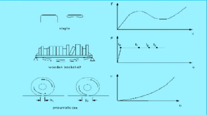
Damages in the material lead to non-linear behaviour. You encounter structural nonlinearities on a routine basis. For example, whenever you take to piece of papers and staple together and see the metal staples are bent permanently in different shape. If you heavily load a wooden shelf, it will sag more and more as time passes. As weight is added to a car or truck, the contact surfaces between its pneumatic tires and the underlying pavement change in response to the added load. If you were to plot the load-deflection curve for each of these examples, you would discover that they all exhibit the fundamental characteristic of nonlinear structural behaviour changing structural stiffness.
Fig 1.1 Load deflection curves for different types of structural nonlinearities
Nonlinear structural behaviour arises from a number of causes, which can be grouped into these principal categories:
1. Geometric nonlinearities 2. Material nonlinearities
Geometric Nonlinearities
If a structure may get into large deformations, this will changing its geometric configuration and can cause the structure to respond nonlinearly.
Geometric nonlinearity is characterized by "large" displacements and rotations.
Material Nonlinearities
Copyrights © International Journal of Intellectual Advancements and Research in Engineering Computations,
viscoelasticity, and viscoelasticity will give rise to non linearities that can be time, rate, temperature, and stress-related.
Swelling will induce strains that can be a function of temperature, time, neutron flux level (or someanalogousquantity), and stress.
As mentioned above Visco-plasticity can occur because of fracture. This occurs at near crack tip field with certain radius of curvature. Plasticity region highly depend of type of material in which fracture situated and plane strain and plane stress conditions. Non-linearity due to crack is differ from non-linearity occur due to plasticity around the crack tip.
Cracks
A crack is a type of fracture that separates a solid body into two, or more, pieces under the action of stress. There are three types of modes of failure.
Mode I: The forces are perpendicular to the crack (the crack is horizontal and the forces are vertical), pulling the crack open. This is referred to as the opening mode.
Mode II: The forces are parallel to the crack. (The crack is horizontal and the forces are also horizontal) In that one force is pushing the top half of the crack back and the other is pulling the bottom half of the crack forward, both along the same line. This creates a shear crack .The crack is sliding along itself. It is called in-plane shear because the forces are not causing the material to move out of its original plane.
Mode III: The forces are perpendicular to the crack (the crack is in front-back direction, the forces are pulling left and right). This causes the material to separate and slide along itself, moving out of its original plane (which is why it’s called out-of-plane shear).
Fig.1.2 Crack propagation modes
The study of weakness split engendering in metals has been of first significance concerning how well designing structures withstand the mind boggling stacking conditions that they regularly experience. Many examinations have been done to research exhaustion break engendering because of a solitary or blended mode as it were. Yet, by and by, the stacking could be variable and the imperfection development bearing alterable. So it is important to
because of these heap varieties. In this way, a precise expectation of weariness life requires a sufficient assessment of these heap communication impacts. Break development in structures is a component of the abundancy, push proportion, recurrence and the irregular idea of the heap. The evaluation of the conduct of structure subject to variable plentifulness stacking (VAL) is more unpredictable than when subjected to consistent adequacy stacking. The greater part of fatigue crack growth studies is concentrated on single-mode loading and is usually performed under mode-I loading condition. Unfortunately, single- mode loading seldom occurs in practice, and in many cases cracks are not normal to the maximum principal stress direction.
Debonds
Debonds are type of fractures where the bonding between the material molecules are
vulnerable to breakage. These occur in weak strength materials more often. These are due to mould defects during manufacturing.
Delaminations
One of the most commonly observed failure modes in composite materials is delimitation, a separation of the fibre reinforced layers that are stacked together to form laminates. The most common sources of delimitation are the material and structural discontinuities shown in figure delimitations occur at stress free edges due to the mismatch in properties of the individual layers, at ply drops where thickness must be reduced, and at regions subjected to out-of-plane loading such as bending of curved beams.
Different types of delaminations
Introduction to Clutches
A clutch is a mechanical device that provides for the transmission of power (and therefore usually motion) from one component (the driving member) to another (the driven member) when engaged, but can be disengaged.
Clutches are used whenever the transmission of power or motion must be controlled either in amount or over time (e.g., electric screwdrivers limit how much torque is transmitted through use of a clutch; clutches control whether automobiles transmit engine power to the wheels).
In the simplest application, clutches connect and disconnect two rotating shafts (drive shafts or
line shafts). In these devices, one shaft is typically attached to a motor or other power unit (the driving member) while the other shaft (the driven member) provides output power for work.
A "hard" clutch is also a common problem. All clutches require some amount of force to depress fully. If you have to press hard on the pedal, there may be something wrong. Sticking or binding in the pedal linkage, cable, cross shaft, or pivot ball are common causes. Sometimes a blockage or worn seals in the hydraulic system can also cause a hard clutch.
Copyrights © International Journal of Intellectual Advancements and Research in Engineering Computations,
“clutch release bearing”. This bearing applies force to the fingers of the spinning pressure plate to release the clutch. If you hear a rumbling sound
when the clutch engages, you might have a problem with the throw-out.
Theoretical Calculations
Aluminium Alloy 7475
Young modulus = 70300MPa Poisson’s ratio = 0.33 Density = 2.18 g/ cc
Crack Extension Force
ℓ c = πασ2/EWhere critical value of ℓ σf = (E ℓ c/ π α )1/2 Where
ℓ c = Fracture toughness E = Young Modulus ℓ c = πασ2/E
= π × 5 × (5172)/ 70300 = 59.723mm
σf = (E ℓ c /π α)1/2
= (70300 × 59.723 / 3.14 × 5)1/2 = 516.997 N/mm2
Strain – Energy Release Rate
Uo = ½ PδP = E δ = P2 / 2E
= 0.38202 /2 × 70300
Uo = 1.0378 × 10⁻⁶
Stress – Intensity Factor
σ x =σy= σ (α /2r)1/2 and τxy = 0 k= Stress intensity factor K = σ √ π α
K = σ √ π α = 517 √ 3.14 × 5 k = 2049.04N/mm2
σ x= K / √2 × π × r [cos / 2 (1- sin / 2 sin 3 / 2) ] σy = K / √2 × π × r [ cos / 2 ( 1+ sin / 2 sin 3 / 2) ]
τxy = K / √2 × π × r [ Sin / 2 Cos / 2 Cos 3 / 2 ) ] σ x= K / √2 × π × r [cos / 2 (1- sin / 2 sin 3 / 2 ) ] = 2049.04 / √ 2 × π×303 [ cos / 2 ( 1- sin / 2 sin 3 / 2 )
Where Ѳ = 0 σ x= 46.961N/mm
2
σy= K / √2 × π × r [ cos / 2 ( 1+ sin / 2 sin 3 / 2 ) ]
= 2049.04 / √ 2 × π×303 [cos / 2 ( 1+ sin / 2 sin 3 / 2 ))
Where = 0 σy = 46.961 N/mm2
= 2049.04 / √ 2 × π×303[sin / 2 Cos / 2 Cos 3 / 2 ) ]
= 0
σ x= σy = σ (α /2r ) ½
= 517 (5 / 2× 303)= 46.961N/mm2
Plasticity Corrections
σy= K / √ 2 × π × rp= σ o rp = K 2 / 2 π σo2 = 2049.042 / 2 π (46.961)2 rp = 303.002mm
Crack Opening Displacement
δ = 4 σ / E (2 α r p) ½
= 4 × 521 / 70300 ( 2 × 5 × 303.002 ) δ = 1.61925mm
Aluminium Alloy6061
Young Modulus = 68900N/mm2 Poisson’s ratio =0.33
Density = 2.7gm/ cc
Crack Extension Force
ℓ = πασ2/E
Where critical value of ℓ σf = (E ℓ c/ π α )1/2 Where
ℓ c = Fracture toughness E = Young Modulus ℓ c = πασ2/E
= π × 5 × (1242)/ 68900 ℓ c = 3.5054
σf = (E ℓ c /π α)1/2
= (68900 × 3.5054 / 3.14 × 5)1/2 = 124.030
Strain – Energy Release Rate
Uo = ½ Pδ = P2 / 2E
= 0.38202 /2 × 68900 U o = 1.05895 × 10⁻⁶
Stress – Intensity Factor
σ x= σy= σ (α /2r)1/2 and τ xy = 0 k= Stress intensity factor K = σ √ π α= 124 √ 3.14 × 5 k = 491.45N/mm2
σ x= K / √2 × π × r [ cos / 2 ( 1- Sin / 2 Sin 3 / 2 ) ]
σy=K / √2 × π × r [ cos / 2 ( 1+ sin / 2 Sin 3 / 2 ) ]
τxy = K / √2 × π × r [ sin / 2 Cos / 2 Cos 3 / 2 ) ] σ x= K / √2 × π × r [ cos / 2 ( 1- Sin / 2 Sin 3 / 2 ) ]
= 491.45 / √ 2 × π×303 [ cos / 2 ( 1- Sin / 2 Sin 3 / 2 )
Where = 0 σ x= 11.263N/mm
2
σy = K / √2 × π × r [ cos / 2 ( 1+ sin / 2 sin 3 / 2 ) ]
= 491.45 / √ 2 × π×303 [cos / 2 (1+ sin / 2 sin 3 / 2 ))
Where = 0 σy = 11.263 N/mm
2
τxy = K / √2 × π × r [sin / 2 Cos / 2 Cos 3 / 2 ) ] = 491.45 / √ 2 × π×303[sin / 2 Cos / 2 Cos 3 / 2 ) ]
= 0
σ x= σy = σ (α /2r ) ½ =124 (5 / 2× 303) ½ = 11.263N/mm2
Plasticity Corrections
σ y = K / √ 2 × π × rp= σ o rp = K 2 / 2 π σo2 = 491.452 / 2 π (11.263)2 rp = 303.019mmCrack Opening Displacement
δ = 4 σ / E (2 α r p) ½= 4 ×124 / 68900 (2 × 5 × 303.019) ½ δ = 0.3962mm
S2 Glass
Material Properties
Young modulus – 86900N/mm2 Poisson’s Ratio – 0.23
Density – 2.46 gm/ cc
Crack Extension Force
ℓ c = πασ2/EWhere critical value of ℓ σf = (E ℓ c/ π α )1/2 Where
ℓ c = Fracture toughness E = Young Modulus ℓ c = πασ2/E
Copyrights © International Journal of Intellectual Advancements and Research in Engineering Computations,
σf = (E ℓ c /π α)1/2
= (86900 × 4322.328 / 3.14 × 5)1/2 = 4891.239 N/mm2
Strain – Energy Release Rate
Uo = ½ Pδ= P2 / 2E= 0.38202 /2 × 86900 U o = 8.39608 × 10⁻⁷
Stress – Intensity Factor
σ x =σ x = σ (α /2r)1/2 and τ xy = 0 k= Stress intensity factor
K = σ √ π α = 4890 √ 3.14 × 5 K = 19380.67N/mm2
σ x = K / √2 × π × r [cos / 2 ( 1- sin / 2 sin 3 / 2 ) ]
σy = K / √2 × π × r [cos / 2 ( 1+ sin / 2 sin 3 / 2 ) ]
τxy = K / √2 × π × r [sin / 2 cos / 2 Cos 3 / 2 ) ] σ x = K / √2 × π × r [cos / 2 (1- sin / 2 sin 3 / 2 ) ]
= 19380.67 / √ 2 × π×303 [cos / 2 (1- sin / 2 sin 3 / 2)
Where = 0
σ x = 444.184N/mm2
σy = K / √2 × π × r [cos / 2 ( 1+ sin / 2 sin 3 / 2 ) ]
= 19380.67 / √ 2 × π×303 [Cos / 2 ( 1+ sin / 2 sin 3 / 2 ))
Where = 0 σy = 444.184 N/mm2
τxy = K / √2 × π × r [ sin / 2 Cos / 2 Cos 3 / 2 ) ] = 19380.67 / √ 2 × π×303[sin / 2 Cos / 2 Cos 3 / 2 ) ]
= 0
σ x= σy = σ (α /2r ) ½ =4890(5 / 2× 303) ½ = 444.184N/mm2
Plasticity Corrections
σy = K / √ 2 × π × rp= σ o rp = K 2 / 2 π σo2= (19380.67)2 / 2 π (444.184)2 rp= 302.99mm
Crack Opening Displacement
δ = 4 σ / E (2 α r p) ½= 4 ×4890 / 86900 (2 × 5 × 302.99) ½ δ = 12.389mm
RESULTS AND DISCUSSIONS
Without Crack
Aluminium alloy 7475
Structural Analysis
Table 6.1
Displacement(mm) Stress(N/mm2) Strain
0.370E-03 0.345338 0.724E-05
Dynamic Analysis
Table6.2
Displacement(mm) Stress(N/mm2) Strain
10SEC 0.985294 0.034543 0.725E-05 20SEC 0.122805 0.069068 0.769E-03 30SEC 0.002104 0.985294 0.212E-04
Aluminium Alloy 6061
Table 6.3: Structural Analysis
Displacement(mm) Stress(N/mm2) Strain
Table 6.4: Dynamic Analysis
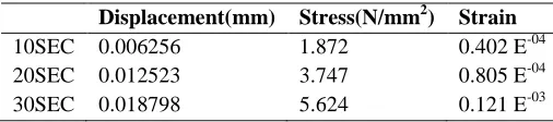
Displacement(mm) Stress(N/mm2) Strain
10SEC 0.006256 1.872 0.402 E-04 20SEC 0.012523 3.747 0.805 E-04 30SEC 0.018798 5.624 0.121 E-03
S2 Glass
Table 6.5: Structural Analysis
Displacement(mm) Stress(N/mm2) Strain
S2 GLASS 0.00518 1.932 0.299 E-04
Table 6.6: Dynamic Analysis
Displacement(mm) Stress(N/mm2) Strain
10SEC 0.002401 1.629 0.261 E-04 20SEC 0.004803 3.259 0.521 E-04 30SEC 0.007205 4.89 0.782 E-04
Table 6.7: Dynamic Analysis
Displacement(mm) Stress(N/mm2) Strain
10SEC 0.393E-03 0.300738 0.416E-05 20SEC 0.457E-03 0.676106 0.918E-05 30SEC 0.686E-03 1.014 0.138E-04
With Crack
Aluminium Alloy 7475
Table 6.8: Structural Analysis
Displacement(mm) Stress(N/mm2) Strain
Aluminium7475 0.382E-03 0.355466 0.751E-05
Table- 6.9: Dynamic Analysis
Displacement(mm) Stress(N/mm2) Strain
10SEC 0.61265 18.654 0.396E-03 20SEC 0.28624 17.689 0.375E-03 30SEC 0.28213 17.526 0.381E-03
Aluminium Alloy 6061
Table 6.10: Structural Analysis
Displacement(mm) Stress(N/mm2) Strain
Aluminium6061 0.390E-03 0.355561 0.766E-05
Table 6.11: Dynamic Analysis
Displacement(mm) Stress(N/mm2) Strain
Copyrights © International Journal of Intellectual Advancements and Research in Engineering Computations,
S2 Glass
Table 6.11: Structural Analysis
Displacement(mm) Stress(N/mm2) Strain
S2 GLASS 0.023986 18.12 0.291E-03
Table 6.12: Dynamic Analysis
Displacement(mm) Stress(N/mm2) Strain
10SEC 0.023999 18.128 0.291E-03 20SEC 0.048007 36.264 0.583E-03 30SEC 0.072003 51.391 0.874E-03
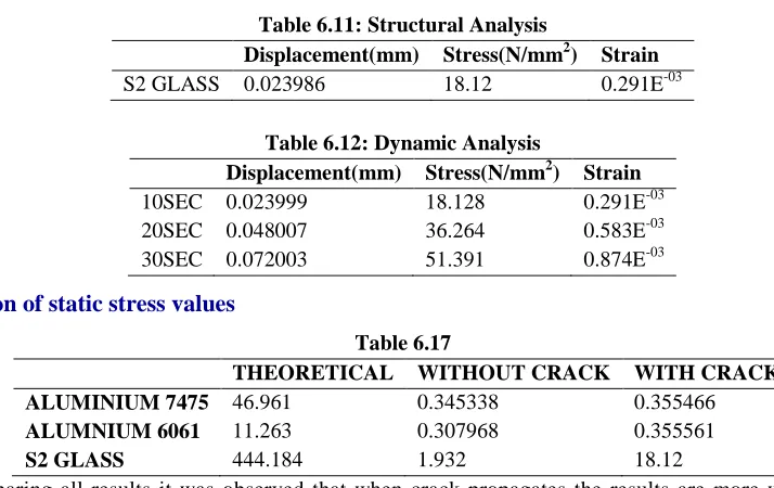
Comparison of static stress values
Table 6.17
THEORETICAL WITHOUT CRACK WITH CRACK
ALUMINIUM 7475 46.961 0.345338 0.355466
ALUMNIUM 6061 11.263 0.307968 0.355561
S2 GLASS 444.184 1.932 18.12
By comparing all results it was observed that when crack propagates the results are more when compared with no crack
Graphical Representation of Stress Values of Dynamic Analysis – Without Crack and With Crack
Aluminium 7475
Fig 6.1Aluminium 7475
Aluminium 6061
Fig 6.2Aluminium 6061
0 5 10 15 20
10Sec 20Sec 30Sec
str
e
ss M
Pa
without crack
with crack
0 20 40 60
10Sec 20Sec 30Sec
str
e
ss M
Pa without
crack
S2 Glass
Fig 6.3 S2 Glas
CONCLUSION
In this thesis, a clutch plate is analysed for crack propagation for different materials Aluminium alloy 6061, Aluminium alloy 7475 and Composite materials S2 Glass. Theoretical calculations are done to determine stress intensity factor, crack extension force, crack opening displacement.
By observing the theoretical calculations, the stress intensity factor and crack opening displacement are more for composite materials.
Dynamic analysis is done in finite element analysis software ansys. The analysis is done on the
clutch before crack and propagated crack after load steps.
By observing the analysis results, the stress values are more for composite materials and when the crack is started stress values of the composite materials increases more than the condition of no crack so the composite materials fails faster once the crack propagates.
So we can conclude that if the crack propagates in the composite materials, they tend to fail faster than aluminium alloys thereby reducing their life. So care should be taken for composite materials not to get the crack.
REFERENCES
[1]. Machine Design by R.S. Khurmi
[2]. Mechanical Metallurgy by George E. Dieter [3]. Fracture mechanics by Dr.P.J.G. Schreurs
[4]. Fracture mechanics by Victor E. Saouma, Dept. of Civil Environmental and Architectural Engineering University of Colorado, Boulder, CO 80309-0428
[5]. Failure of Materials in Mechanical Design: Analysis, Prediction, Prevention, 2nd Editionby Jack A. Collins
0 10 20 30 40 50 60
10Sec 20sec 20sec
str
e
ss M
Pa without
crack