Volume-5 Issue-2
International Journal of Intellectual Advancements
and Research in Engineering Computations
Implementation of automation technology in ink jet printing
machine using 5m methodology
M. Shanmugam1, N. Ananth2, M. Jagadeeswaran2, S. Arun Kumar2, P. Pradeep2
1
Assistant professor, Department of Mechanical Engineering,
2
U.G Scholar, Department of Mechanical Engineering, Nandha Engineering College
Abstract - The advancement in technology has presented many modifications in ink jet printers and its method to print. The emerging technologies through the implementation of highly advanced printers consumes more energy, for this a new idea of spring mechanisms are to be promoted. The spring used in this mechanism is to be designed which includes properties like stiffness, deformation, stress, elasticity of the spring, time calculation and productivity. Digital models are used to analyze the existing method used for automation and to promote a new method for better management and improvement. Then this mechanism is analyzed and tested in popular horn manufacturing units, label printing machine with the help of 5M methodology. We compare our new spring technique with simulations software like solidworks, Ansys workbench and use the results to determine the practical range of validity of our analytical model.
Index terms - Inkjet printing, 5M methodology, spring mechanism, stiffness, ANSYS workbench 14.5
1. INTRODUCTION
According to the 5M methodology, improving the performance of the existing method is one of the highest priorities over the next several decades. To achieve this ambitious goal, many researches are under development as integrated and standardized methodologies, while tools to monitor and assess real sufficient one are still missing
.
2
. 5MMETHODOLOGY5-M Method or 5-Factor Method is a simple method of analyzing the causes and consequences (problems) based on the following five causes:
A. MANPOWER - causes are in humans, people. We can increase the efficiency of workforce by following some best practices in manpower management. As
far as manufacturing automation has come, we’ll never eliminate the need for skilled workers in the manufacturing process. In fact, many manufacturers are finding a shortage of highly-skilled workers with enough experience to perform today’s complex production procedures. In order to overcome this challenge, companies must focus on maintaining the efficiency of their workforce if they hope to increase productivity. It include three main terms:
Experience
Self- Discipline
Institutional habits
B. MACHINES - causes are in equipment, such as machinery, computers, tools, instruments, technology. Design, installation and maintenance of durable precise machines will reduce waste, saves money and create more precise products. Each machine in a manufacturing process must be precisely designed, built, and programmed to perform its function with precision, reliability, and durability. Machines that are reliable, durable, and efficient create a truly lean manufacturing process. It includes the following terms:
Work Holding
Tooling
Application
C. MATERIALS - causes are in defect or material properties. Attention to quality, cleanliness, performance and environment will help increase in manufacturing process. . In the 5M’s of efficiency, materials play an important role in the 5M’s of efficiency, often providing a multitude of benefits including:
Leaner material costs
Decreased processing time
Cleaner work pieces
More precise products
Not to overstate the obvious, but good materials make good products. Proper selection of your materials from base material to tooling, to metal working fluids, will improve the quality of the work piece. It includes the following characteristics:
Quality
Cleanliness
Performance
Environmental-Efficiency
D. METHODS - causes are in the rules, regulations, laws or standards. By combining latest methods in green manufacturing with time tested methods from history will create efficient manufacturing process. Methods used in lean manufacturing must be carefully designed and followed to maximize the efficiency of your operation. Each step should be carefully designed to meet the specifications of the part. The following factors are considered:
Processes
Error Proofing
Statistical Process Control (SPC)
Failure Mode Effect Analysis (FMEA)
E. MANAGEMENT - causes are in improper management. Precise measurement of statistics within machines and across the manufacturing floor provides feedback which helps to keep our operation performing at maximum profitability. - Measurement of processes, machines, and other assets is critical to a lean manufacturing plan. Without accurate measurement (and reporting) how will you know if your equipment is performing at its optimal level? Measurement of the following metrics will help keep lean processes on track and performing at their greatest efficiency and prevent bottlenecks. The factors to be considered are:
Measuring Overall Equipment Effectiveness (OEE)
Powerful, Flexible Manufacturing Efficiency Software
3. DEVELOPMENTOFSOLUTION
At first we completely examined and clearly understand the problem, then we analyzed all the possible solutions to do our case study. We have discussed four possible ways:
A. BY USING MANUAL METHOD
A manual (human labor) can perform the printing operation. He place the box in the printing position and by pedal pressing the printer prints each box and he continuously perform the operation manually. By doing the work manual there will be some errors. So we place the sensor near the printer for checking the boxes.
B. BY USING PLC CONTROLLER
We planned to introduce a conveyor belt near the ink jet printing machine which is controlled using plc. This conveyor belt carries the boxes to print the necessary label on them. The time delay for printing each box is calculated and the conveyor is moved correspondingly using PLC (Programmable Logic Circuit) (or) we can use pneumatic and hydraulic actuators for controlling the movement of boxes in and out.
C. BY USING SPRING TECHNIQUE
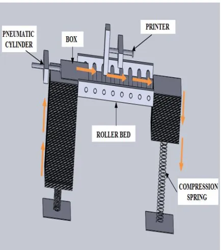
We can place some boxes in the plate which is placed above the spring loaded container with some tension. We can place roller bed in the place of printers printing position. In the opposite side, we can place another spring loaded container which is used for collecting printed boxes. A double acting pneumatic cylinder is placed near the first container for moving the box to the printing position. Sensors are used near both printer and pneumatic cylinder for controlling their motion. When boxes in the first container are moved by the cylinder the roller bed pushes to the printer. After printing it is moved to the second container.
D. BY USING ROBOTICS ARM
arm which collects the boxes. After collecting defined boxes it will move them to another conveyor which moves them to the location where horns are needed to be boxed. Main thing is no manual work needed, a great advantage and at the same time excess of amount to be invested and lots of time duration calculations to be made with effort.
E. SELECTION PROCESS
By comparing all the process by 5M Methodology, manual method will have low production and less quality. It may have some errors. The PLC method uses lots of circuit and power consumption and also time duration to be maintained. So it will be costly when compared. The robotic arm method is very expensive when compared to all other methods, because the arm functioning needs lots of power and codes are to be written to perform their operation.
Similarly time calculations are difficult in this method. After comparison, the spring technique is very cost effective and needs less power. Similarly time calculations are too easy in this method. It is the best suited method for this inkjet printer in the assembly line.
4. SOLUTIONS
Fig 4.1 3D Model of the spring technique
Load the box (approximately 100 boxes) in the spring loaded container, which pushes the boxes in opposite direction due to compression or suspension in it (upward movement).
Now by using pneumatic cylinder, the box is moved to the printing position.
Sensor in the printer senses and passes the command to the printer to print the box.
At the same time, the sensor in pneumatic cylinder sends the signal to retract the cylinder to starting position.
Now boxes in the container moves up due to compression acting on it. Again the cylinder moves the box to the printing position.
By this action, the printed box in the position moves to another spring loaded container which collects the printed boxes.
In this container the box are loaded so it compress the spring and moves downward (downward movement) as shown in Fig 4.1.
The process continues until the required boxes are printed and to be reloaded.
4.1 COMPARISON OF BOXES
we have compared all the six types of boxes and tabulated their mean, minimum and maximum (lengths, width, thickness and weight) as shown below in Table 4.1.
5. DESIGNING OF SPRING
Springs are elastic bodies (generally metal) that can be twisted, pulled, or stretched by some force. They can return to their original shape when the force is released. In other words it is also termed as a resilient member.
A. COMPRESSION SPRING
It is designed to operate with a compression load, so the spring gets shorter as the load is applied to it. When a spring is compressed or stretched from its resting position, it exerts an opposing force approximately proportional to its change in length.
B. MATERIAL USED
Carbon steels are steels with carbon content up to 2.1% by weight American Iron and Steel Institute (AISI). It is very tough and it can be hardened and tempered.
C. DIMENSIONS
D. CALCULATION OF STIFFNESS
Where,
G- Shear modulus of material, d- Wire diameter,
D- Spring diameter, n- No. of coils. For carbon steel,
G = 80 Gpa = 80*10^3 N/mm2 By calculating,
Spring stiffness R = 0.5206 N/mm E. SOFTWARE TOOL USED
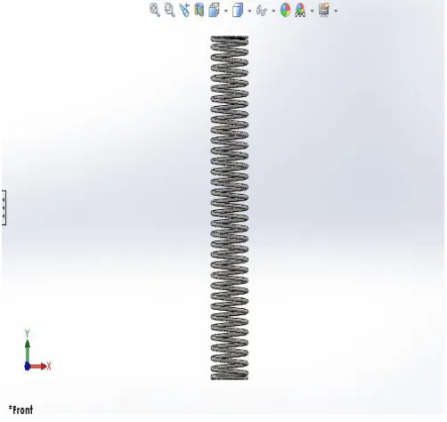
Fig 5.1 Carbon Steel Spring
First we draw the spring for the above dimension in SOLIDWORKS 2014 software as shown below in the figure 5.1.
Fig 5.2 Total deformation
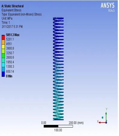
Then we analyzed deformation, stress analysis and elastic strain developed over the spring as shown in the corresponding figures 5.2, 5.3 and 5.4.
Fig 5.3 Equivalent (von mises) stress
Figure 5.4 Equivalent elastic strain
F. COMPARISON CHART
After that we have calculated the current (manual) work with this spring technique. In manual work the person prints about 3000 boxes per shift and this operation involves pedaling. By implementing this technique we can double the production. For this clear understanding, we have plotted the chart in Fig 5.5.
0 1000 2000 3000 4000 5000 6000 7000
MANUAL METHOD NEW METHOD
N
O
.O
F
BO
XE
S
Fig 5.5 Comparison of production of boxes
VI. CONCLUSION
time duration of the manual work by eliminating the pedaling operation. It helps to increases the production of the assembly line correspondingly.
By analyzing with 5M methodology it shows that initial investment is small so it satisfies money. Method is too simple by using spring technique, thus methodology is very simple. The material are readily available in the market so it is easily purchased and at last over all maintenance of this process needs less man power.
VII. REFERENCE
[1] Newman JD, Turner APF, Marrazza G. Ink-jet printing for the fabrication of amperometric glucose biosensors. Anal Chim Acta 1992;262(1):13–7. [2] Xu T, Petridou S, Lee EH, Roth EA, Vyavahare NR, Hickman JJ, Boland T. Construction of high-density bacterial colony arrays and patterns by the ink-jet method. Biotechnol Bioeng 2004; 85(1):29– 33.
[3] Ming-Kai Tse, David J. Forrest, and John C. Briggs, “Automated Print Quality Analysis for Digital Printing Technologies,” PPIC/JH ’98 July15-17, 1998 Tokyo.
[4] Blanchard AP, Kaiser RJ, Hood LE. High-density oligonucleotide arrays. Biosensors Bioelectron 1996; 11(6–7):687–90.
[5] Roda A, Guardigli M, Russo C, Pasini P, Baraldini M. Protein Micro deposition using a conventional ink-jet printer. Biotechniques 2000; 28(3):492.
[6] Design & Optimization of Helical Compression Spring by Unmesh A. Vibhuteon on Journal of Thermal Engineering and Technology under Volume 1 Issue 2
[7] Inkjet printing for high-throughput cell patterning by E.A. Roth, T. Xu, M. Das, C. Gregory, J.J. Hickman, T. Boland* Department of Bioengineering, Rhodes Research Center, Clemson University, 502 Rhodes Hall, Clemson, SC 29634, USAReceived 9 July 2003; accepted 20 October 2003