© 2017 IJSRSET | Volume 3 | Issue 8 | Print ISSN: 2395-1990 | Online ISSN : 2394-4099 Themed Section : Engineering and Technology
A Fast Method for Haze removal In Remote Sensing Image By
Using Guided Filter
1
M.Vasudeva Reddy, 2Dr.T.Ramashri 1
Research Scholar, 2Professor 1
Rayalaseema University, 2S.V University Kurnool, Andhra Pradesh, India
E-mail:[email protected], [email protected]
ABSTRACT
The visibility of the open-air images is degraded on account of bad atmosphere conditions. Robust solutions to this problem, a simple and narrative method to eliminate the haze from satellite remote sensing images using Guided filter. The mission is challenging due to variations in dark channel prior, air light, transmission map and radiance map. The presence of haze in the atmosphere degrades the quality of images capture by visible camera sensors. The removal of haze is typically performed under the numerical methods. Due to haziness, an image generally lost color and edges. So dehazing technique restores edge losses and color impacts badly. The method performs a per-pixel treatment, which is straightforward to implement and then apply the guided filter to improve the image quality. Our key perception is that pixels in a given group are regularly non-local, they are spread over the whole image plane and are situated at various separations from the camera. Within the sight of vagueness these fluctuating separations mean distinctive transmission coefficients. Experimental results demonstrate that the proposed method can allow a very fast implementation, it is effective for visual appealing, the quality of reconstructed image is usually specified in terms of Peak Signal to Noise Ratio (PSNR), Mean Square Error (MSE) and normalized cross correlation compared to some state-of-the-art methods.
Keywords: Bilateral Filter, Guided Filter, Psnr, Mse and Normalized Cross Correlation.
I.
INTRODUCTIONHaze is an annoying factor when it shows up in the image since it causes deprived visibility. This is the major problem used in various fields including agriculture, forestry, metrology, and military. But widespread use of satellite remote sensing images is predicated on high-quality images.
Poor visibility due to haze is caused by perched particles in the atmosphere. The incoming light from a scene or object is scattered due to this and hence it is attenuate till it reaches the camera. This degradation will cause the image to lose contrast and color correctness. This knowledge is commonly used for dehazing problems. We also adopt this clue to solve the haze removal problem. Image haze[1] removal has gotten a growing attention recently. More and more methods are introduced in the past three years. Nevertheless,
Dehazing is a challenging subject since the haze is dependent on the unknown depth information. Often, the images of outdoor scenes are degraded by bad weather conditions. In such cases, atmospheric phenomena like haze degrade significantly the visibility of the captured scene Dark channel [2][9] in the bordering pixels window to guesstimate the airlight and transmission map followed by soft matting to refine the image.
The method considerably enhances the quality of hazy images. Also, the method generate transmission map which cannot ensure edge preserving and as a result sharpness of the image degrades. Dehazing is highly required in consumer photography and computer vision applications because many computer vision applications are experience from low-contrast scene radiance. For example there is a problem of haze in under water images. There are many schemes available to remove haze from outdoor image.
II.
EXISTING METHOD
2.Bilateral Filter
A bilateral filter is a non-linear, edge-preserving, and
smoothing filter for images. It replaces the intensity of each pixel with a weighted average of intensity values from nearby pixels[8]. This weight can be based on a Gaussian distribution. Crucially, the weights depend not only on Euclidean distance of pixels, but also on the radiometric difference. It is observed that the transmission delineate haze exclusion approach creates blocks and artifacts along the edges. Yet, soft matting by processing 3 transmission maps using 3 different block sizes (3*3,5*5,7*7) and generate radiance map for all block sizes followed by cross bilateral filtering. The transmission maps and comparing radiance images. For a greater square size the impact is considerably more however it reduces noise. It can generate more artifact in the image for block size 7*7 generate more artifacts in the image along the edges as compared to 3*3. Whereas the noise level in 7*7 is less as compared to 3*3.
This approach of ours reduces noise and eliminates the need for soft matting thus improving the instance required for processing. Bilateral filter does weighted averaging of pixels across multiple frames (radiance image) obtained. The radiance map corresponding to 3*3 block is considered as a position as it conserves most of the edge or gradient information in the image. The filtering is performed on intensity(Y) of the radiance image.
Where is the filtered output at (i,j) pixel location, N is the number of frames, k1 indicates block size, is a constant and K is normalizing factor given by
The value of σm depends on the uniqueness of noise.
The weights depend on difference of pixel of current frame from pixel of reference frame. If the deviation is
less the weights tend to become equal, otherwise haze in the Image reduces the contrast of captured image. Hence, contrast enhancement is performing to restore the contrast. Since the noise component is reduced in the previous step the contrast may be enhanced without enhancing noise.
Where m is a threshold, r(x,y) is input intensity and is contrast enhancement factor to produce output I(x,y). Based on empirical observation using a number of images we assumed m to be 0.8 times the mean intensity
of the image and γ =2.0 in the present work.
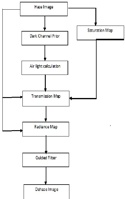
III. PROPOSED METHOD
In surveillance system, remote sensing systems, and underwater, the image facade is subject to atmospheric condition such as haze. Haze formation model [10][11] is widely used in computer vision and image processing. This model used for the formation of image in the presence of bad atmospheric conditions. Image quality is degraded due to the presence of extensive particles in the atmosphere which have significant size between 1-10 μm.
The light coming from a camera is engrossed and scattered by these atmospheric particles. Assume that this haze model is linear model. From the definition of linearity in this model [6] only pixel position is changed. This invisibility is occurred by two primary: Direct attenuation and Air light. And it is describe as follow:
I(x) = J(x)*t(x) + A*(1-t(x)) (1)
Where I(x) is the observed intensity of the xthpixel, J(x)
is the scene radiance vector (the true color that we want to recover), A is the atmospheric light, and t is the transmission medium describing the portion of the light that is not spread and reaches direct to the camera.
In the equation first term, J(x)*t(x) is called the direct attenuation; the second term, A*(1-t(x)) is called air light. This haze model is directly extended to each RGB component of a color image.
Figure 2. Block diagram of Proposed Method
Dark Channel Prior
Dark channel prior [3] to the haze-free outdoor images, which supports that most of local regions exclusive of the sky have very low intensity in at least one color channel. The intensities of these dark pixels are mainly caused by Shadows, Colorful objects or surfaces and Dark objects or surfaces.
Similarly, it has been observed that the pixels in hazy regions have high values in all color channels. The dark channel is defined as where is a channel of and is a local neighborhood centered at. Based on the dark channel prior, is a constant in a local image patch. Thus, we define the local transmission as and take the min operation with a local patch on.
It is roughly good but contains some block effects, since the atmospheric light is not always constant in a patch. That is to say, a local patch may contain the region where the scene depth is discontinuous. For the sake of avoiding this problem, estimated atmospheric light using Guided filter on the least component of the hazy image.
Dark channel prior [2][9] to the haze-free outdoor images, which supports that most of local regions excluding the sky have very low intensity in at least one color channel. The intensities of these dark pixels are mainly caused by shadows, colorful objects or surface and dark objects or surfaces.
It based on the observation that at least one color channel has some pixels whose intensity values are very low and close to zero. In this it is computed as
= ((1- )* ( ) (2)
Where Jca color channel of J, µ is a mean and is a
standard deviation of r, g, b intensity values and Ω(x) is a local patch centered at x.
We consider top 1% pixels in computing air light and
find the pixel which has maximum value of in its dark
channel among the pixels based on equation(2). The value of I at that pixel is considered as airlight.
Estimation of atmospheric light
Generally, the full of atmosphere light is always considered as the brightest intensity in the entire image because a large amount of haze makes the object scene brighter than itself. The basic idea of this method is that atmospheric light should be estimated from the region with brighter intensity [6] and less surface. The atmospheric light is estimated as the value that has the least distance to the pure white. Pad Array consists of zeros. It is based on pad size, is a vector of nonnegative integers that specifies both the amount of padding to add and the dimension along which to add it. The value of an element in the vector specifies the amount of padding to add. The sort of the element in the vector specifies the dimension along which to add the padding. In this work, we opt for this method since it is simple but efficient. However, it is not robust because the estimated atmospheric light may be the noise. So we stare the mean value of the top 5% brightest values in the selected region as the atmospheric light for rejecting the noise influence successfully.
Saturation Map
It converts the Haze image to the equivalent HSV image
[10]. RGB is an 3 image array whose three planes
HSV is returned as an 3 image array whose three planes contain the Hue, Saturation and value[7] components of the image.
Transmission Map and Radiance Map
It is observed that the saturation [4] of color in a hazy image decreases with the density of haze which in turn depends on depth or distance of the object. In this method we unite saturation map and airlight to get a more accurate transmission map and clearer image [5]. The transmission map is calculated by using
t=1-f(S)( )((1- )* )) (3)
where f(s) depends on the saturation of the input image at x. It is expressed as
f(S)=0.8-(0.2*S) (4)
where S is saturation of the pixel (0≤S≤1). We map saturation value of the pixels to f(S) to enhance the output as we observed lesser saturation in an object that are far away and have more haze. If the saturation is less, f(S) will be more and vice-versa. This helps to remove incoherent color patches in the output. We estimate scene radiance as
where t0 is a factor to restrict the noise level.
Guided Filter
Guided filter Performs edge-preserving smoothing on an image, utilizing the substance of a moment picture, called a guidance image, to impact the separating. The direction image can be simply the image, an alternate form of the image, or a totally unique image. Guided image [12] filtering is an area operation, as other sifting operations, yet considers the measurements of a locale in the relating spatial neighborhood in the direction image. The filtering output at a pixel is expressed as a weighted average
j(x) = I (6) The weighted average is given as
where i and j are pixel indexes. The filter kernel wij is a
function of the guidance image j(x) and independent of p. This filter is linear with respect to p. A concrete
Example of such a filter is the joint bilateral filter. The
bilateral filtering kernel wbf is given by
Now we define the guided filter and its kernel. The key assumption of the guided filter is a local linear model between the guidance j(x) and the filter output q.
The solution for linear regression is given by ak, bk
(9)
(10)
Here, μk and σ
2
k are the mean and variance of j(x) in wk,
|w| is the number of pixels in wk and pk∧ = 1|w| j(x)€wk
pi is the mean of p in wk.
The guided filter output is given by
(11)
Finally the guided filter output and the kernel weights can be explicitly expressed as
Some further computations show that Wij(I) = 1.
No extra effort is needed to normalize the weights.
Figure 3 shows Image is effected whereby a loss of contrast in the subject, due to the effect of light scattering through the haze particles
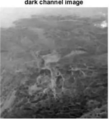
Figure 4. Dark Channel Prior Image
Figure 4 shows the dark channels from hazy images as the minimum value for all the channels and all the pixels in that patch and produce pixels that have values far above zero.
Figure 5. Airlight Image
Figure 5 shows to get the atmospheric light, the average of the pixels in the haze image that correspond to the top lightest 0.01% in the dark channel. Thus it has 3 elements, the average values for each color channel.
Figure 6. Saturation Map
Figure 6 shows converting haze image into Hue saturation value. The columns of the input matrix represent intensities of red, green, and blue, respectively. The columns of the output matrix represent hue, saturation, and value, respectively.
Figure 7. Transmission Map Image
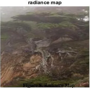
Figure 8. Radiance Map
Figure 8 shows increases the intensity of an image by considering the maximum pixels of airlight,
saturation map and transmission map.
Figure 9. Dehaze Image
Figure 9 shows each individual pixel is replaced with a Guided shaped blob with the same total weight as the original intensity value. It renders small structures invisible and smoothens sharp edges.
IV. RESULTS AND DISCUSSION
Using a newly presented image prior-dark channel prior, haze removal for a satellite remote sensing image additional information is formulated as a particular filtering problem and an improved filtering scheme is based Guided filter. In the on hand algorithm, the airlight, transmission map and radiance map can be estimated and extracted easily. Then using a Guided filter, the transmission map further refined. Results demonstrate the presented method abilities to remove the haze layer and achieve real-time performance layer and achieve real time performance.
Mean Square Error (MSE)
One evident method for measuring this similitude is to compute an error image by subtracting the dehazed image from the original image, and then computing the average energy of the error image. The mean-squared-error (MSE) is the least complex, and the most widely used, full-reference image quality measurement.
Where x(i,j) represents the original (reference) image and p(i,j) represents the dehazed image and i and j are the pixel position of the m×n image.
Peak Signal to noise ratio (PSNR)
The PSNR is evaluated in decibels and is inversely proportional the Mean Squared Error. It is given by the equation 13. The higher the PSNR, the better the quality of compressed or reconstructed image.
Normalized Cross-Correlation (NK)
The closeness between two images can also be quantified in terms of correlation function. Normalized Cross-Correlation (NK) measures the similarity between two images and is given by the equation.
Table 1. Comparison Table
Parameters Bilateral Filter Guided Filter Peak Signal-Noise
Ratio 43.7677 54.9899
Mean Square Error 0.9787 0.2061
Normalized Cross
Correlation 0.0007 0.0035
V. CONCLUSION
For many computer vision applications, haze removal algorithm became more useful. It was found that most of the existing techniques gradient reversal subject that is no technique ic accurate for different kind of circumstances. The problem of over-illumination is a problem for haze from the satellite remote sensing images. We focal point on an improved atmospheric scattering model by considering noise and haze simultaneously. The likelihood of posterior probability based on Guided filter is estimated by tha statistical prior and objective assumption of degraded image. Meanwhile, we focus more on the efficiency by choosing the transmission map to get the scene radiance. Guided filter which can help to attain the balance between dehazing and denoising. The experimental results demonstrate that our approach is effective, especially in challenging scenes with both haze and noise. However, color distortion still exists which will be involved in our future work.
VI. ACKNOWLEDGEMENTS
This paper is dedicated to our Parents, Colleagues and Friends for their support without which the successful completion of this paper is not possible.
VII. VII. REFERENCES
[1] R. Fattal, “Single image dehazing,” ACM
Transactions on Graphics, vol. 27, no. 3, article 72, pp. 1-9, 2008.
[2] T. M. Bui, H. N. Tran, W. Kim, and S. Kim,
“Segmenting dark channel prior in single image dehazing,” Electronics Letters, vol. 50, no. 7, pp. 516-518, 2014.
[3] K. He, J. Sun, & X. Tan, “Single image haze
removal using dark channel prior,” IEEE Transaction on Pattern Analysis and Machine Intelligence, Vol. 33, NO. 12.2011.
[4] S.-C. Huang, J.-H. Ye, and B.-H. Chen, “An
advanced single-image visibility restoration algorithm for real-world hazy scenes,” IEEE Transactions on Industrial Electronics, vol. 62, no. 5, pp. 2962-2972, 2015.
[5] G. Meng, Y. Wang, J. Duan, S. Xiang, and C.
Pan, “Efficient image dehazing with boundary constraint and contextual regularization,” in Proceedings of the 14th IEEE International Conference on Computer Vision (ICCV '13), pp. 617-624, IEEE, Sydney, Australia, December 2013.
[6] S.-C. Huang, B.-H. Chen, and W.-J. Wang,
“Visibility restoration of single hazy images captured in real-world weather conditions,” IEEE Transactions on Circuits and Systems for Video Technology, vol. 24, no. 10, pp. 1814-1824, 2014.
[7] Q. Zhu, J. Mai, and L. Shao, “A fast single
image haze removal algorithm using color attenuation prior,” IEEE Transactions on Image Processing, vol. 24, no. 11, pp. 3522-3533, 2015
[8] D.-Y. Zhang, M.-Y. Ju, and X.-M. Wang, “A
fast image haze removal algorithm using dark channel prior,” Acta Electronica Sinica, vol. 43, no. 7, pp. 1437-1443, 2015.
[9] C. T. Thurow, Real-Time Image Dehazing,
Technical University, Berlin, Germany, 2011.
[10] B. Cai, X. Xu, K. Jia, C. Qing, and D. Tao,
“Dehazenet: An end-to-end system for single image haze removal,” IEEE TIP, vol. 25,no.11, pp.5187-5198, 2016.
[11] K. Tang, J. Yang, and J. Wang, “Investigating
haze-relevant features in a learning framework for image dehazing,” in CVPR, 2014, pp. 2995- 3000.
[12] K. He, J. Sun and X. Tang, “Guided image
filtering,” In Computer Vision - ECCV 2010, vol. 6311, pp. 1-14, 2010.