IJSRSET11841170 | Received : 25 January 2018 | Accepted : 07 February 2018 | January-February-2018 [(4) 1 : 659-671 ]
© 2018 IJSRSET | Volume 4 | Issue 1 | Print ISSN: 2395-1990 | Online ISSN : 2394-4099 Themed Section : Engineering and Technology
659
Extenuation of Voltage Variations and Load Leveling in
wind-DG Microgrid with Back Propagation Based Fuzzy Logic Controller
1Y.Sunil Kumar Reddy, 2K. Raju
1PG Scholar, Department of EEE, Chadalawada Ramanamma Engineering College, Tirupati, Andhra Pradesh, India 2Assistant Professor, Department of EEE, Chadalawada Ramanamma Engineering College, Tirupati, Andhra Pradesh, India
ABSTRACT
This paper proposes a hybrid design of the wind-DG (Diesel Generator) and the microgrid. The microgrid effectively uses the voltage source converter (VSC) as a voltage and frequency controller (VFC). The wind control is actively done by the permanent magnet brushless DC generator (PMBLDCG), and maximum power is potentially obtained by the algorithm of maximum power point tracking (MPPT) which effectively uses a boost converter combined with an incremental conductance (INC) advance. Some of the obtained power is supplied to the consumer loads and the surfeit amount of power is stored in the battery system (BS). BS is included at the end DC connection of VSC which gives load leveling during less or no wind conditions. At the time, when wind generation is unable to meet the load demand and with the combination of these energy resources, a reduced rating diesel engine driven squirrel cage induction generator (SCIG) feeds the loads and VSC at the point of common coupling (PCC). Back propagation feed forward (BPFF) control algorithm is utilized for VF control of VSC. This controller gives harmonic elimination, load leveling and reactive power compensation and furthermore regulates the voltage at PCC. This microgrid is modeled in MATLAB Sim power tools and simulation results are obtained to verify the appropriate working of both the converters and the overall system. A prototype of the microgrid is also developed to validate the design and model through test results. A comparative study of simulated and experimental work is given in detail.
Keywords: Microgrid, SCIG, BPFF, MPPT, Diesel Engine, Load Leveling, Power Quality.
I.
INTRODUCTION
In this period of modernization and digitally technological progression, the way of life and the standard living comforts are mainly
dependent on the electrical equipments and machines, which provide relief, convenience and save time. The electrical energy is mostly obtained from the conventional resources (fossil fuels) which are in constrained and declining phase now. Also, the cost of higher power generation from the conventional energy sources is also a great concern for the researchers. So, the technological efforts are being
the battery storage (BS) systems and some are reported with BS. The systems working without the BS have to derate during high wind speeds and isolations, when the demand is less and the generation is high. By using BS, the surfeit amount of energy can be stored in to it and can be utilized during peak load hours.
Standalone systems are provided with BS to provide stability to the microgrid during excess power generation and load leveling during low generation or peak load demand. Therefore, BS design and size calculation are important for isolated microgrid. Battery charging control is also provided for optimum charging and reliable operation of mocrogrid. Wind energy conversion system and DG set are one of such hybrid combinations, where the wind power is stored in BS and the excess power is utilized to supply the load, while DG set provides AC power to the load. This configuration helps to reduce the fuel consumption and economically utilizes the conventional energy resources.
II.
SYSTEM CONFIGURATION AND CONTROL
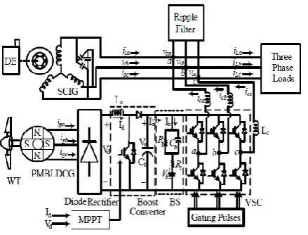
A microgrid comprises of DE (Diesel Engine) driven SCIG and PMSG based WECS as shown in Fig.1. The diesel generator (DG) is feeding 3-phase loads with VSC which regulates voltage and frequency of the system as VFC. The PMBLDC generator converts the wind power to the electrical AC power and induces trapezoidal EMF and quasi square currents, which produces ripple free torque at generator end. This power is rectified into DC using a 3-phase diode-bridge. In the second stage DC-DC conversion is done which uses a boost converter and MPPT is realized with INC algorithm. An inductor makes the DC current smooth and constant and the direction of flow is confirmed by the diode. This is attached at DC link of VSC shunted with BS where battery provides load leveling and required power during low or no wind generation. The battery is charged when the wind power is available and is discharged for low winds and at high load demand. DG system provides
AC power to the AC linear/ nonlinear loads. SCIG has no field windings for voltage buildup, therefore, external reactive power is provided by a delta connected capacitor bank. The produced voltage and frequency are regulated by VFC.
Fig. 1 Schematic diagram of Wind-Diesel microgrid
A. Back Propagation Feed Forward Network Controller
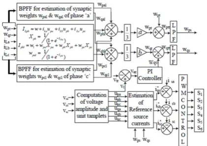
BPFF (Back Propagation Feed Forward) based control algorithm regulates voltage and frequency of the micro grid. In this plan, multi-layered feed forward network is consisted of an input layer, hidden layer and a output layer. The input signal passes in feed forward direction from an input layer towards an output layer on layer by layer basis. Under guidance learning with back-propagation algorithm is executed here which works on the principle of error correction learning to get the desired outputs. Its description is given here according to fig. 2.
In-phase and quadrature layouts of PCC voltage are ascertained as, the peak terminal voltage Vt is defined
as,
√ ( ) (1)
Where vsa, vsb, vsc are phase voltages.
The in-phase unit templates are expressed as,
The quadrature unit templates are defined as,
( )
√ (3)
( )
√ (4)
( )
√ (5)
Reference input currents are registered with synaptic weight estimations of load currents, an active and reactive power segments. Three-layers as input, hidden and an output layers are taken to understand the control. Input layer neurons in its first half bit as a total capacity for active and reactive power part of load current for "b" phase are communicated as,
(6)
(7)
Where w is the underlying estimation of snaptic weight. Both the segments of phase 'a and c' (ILpa, ILpc,
ILqa and ILqc) are figured in the comparative way. These
qualities are gone through second part as actuation capacity of information neurons, which are sigmoid capacities here. The yield of info layer neurons for phase "b" are communicated as,
⁄( ) (8)
⁄( ) (9)
So also conditions for phase "an" and "c" (Xpa, Xpc, Xqa
and Xqc) are additionally processed.
These information layer outputs are bolstered to the information hub of shrouded layer and generation capacity of this layer for phase "b" are communicated as,
(10)
(11)
Different conditions for Ipal, Ipcl, Iqal and Iqcl are
likewise computed in comparative way. Here w1, wpa,
wpb, wpc are a few constants esteems between (0, 1) to
instate the weights. These qualities are refreshed by back spread blunder remedy run the show. Rectified weights of phase "b" active and reactive power parts of load currents wpb and wqb at rth examining time are
as,
( ) ( ) { ( ) ( )} ( )
(12)
( ) ( ) { ( ) ( )} ( )
(13)
So also the refreshed esteems for phase "a" and "c" wpa,
wpc, wqa and wqc are registered. These qualities are
gone through actuation work i.e. sigmoid capacity here. The active and responsive power segment of load currents wpal, wpcl, wqal and wqcl are computed like
that of phase "b" as,
⁄( ) (14)
⁄( ) (15)
Amplitude of the average active and reactive power components of load currents is defined as,
( )
(16)
( )
(17)
DC part of the weighted segment is removed through LPF as these are standardized esteems between (0, 1). Thusly to get actual estimation of active and reactive power segments of load currents they are scaled with a and b calculates separately.
Active power segment of reference information current can be assessed by subtracting wind active segment, wpw expended from active part of load
present as,
(18)
(19)
The reactive component of reference input current is computed using a PI controller. The AC bus voltage error Veis expressed as,
( ) ( ) ( ) (20)
Weighted value of PI controller to regulate terminal voltage at rth instant is calculated as,
( ) ( ) * ( ) ( )+
Where wqv is part of reactive reference input current.
kpv and kiv are proportional and integral gains of PI
controller.
Fig. 2 Schematic diagram of BPFF control Technique
The reference reactive current component is computed as,
(22)
The fundamental reference active and reactive power components of the 3-phase input currents are calculated as,
(23)
(24)
(25)
These 3-phase reference input currents (i*sa, i*sb, i*sc) and sensed input currents (isa, isb, isc ) are compared to
generate PWM pulses for the switching of VSC.
B. Maximum Power Point Tracking (MPPT) Scheme.
The duty cycle of DC-DC boost converter is computed specifically as indicated by the MPPT. For MPPT, the derivative of output power and voltage of diode bridge must be zero i.e. addition of instantaneous conductance and incremental conductance, Z= (Id/Vd+ΔId/ΔVd) is zero. Because of change in any particular parameter, if the point moves towards right hand side and Z becomes negative, the duty cycle increments to keep up the
MPPT. If the point moves towards left hand side and Z becomes positive then the duty cycle declines to keep up the MPPT.
III.
FUZZY LOGIC CONTROLLER
Fuzzy logic is a complex mathematical method that allows solving difficult simulated problems with many inputs and output variables. Fuzzy logic is able to give results in the form of recommendation for a specific interval of output state, so it is essential that this mathematical method is strictly distinguished from the more familiar logics, such as Boolean algebra. This paper contains a basic overview of the principles of fuzzy logic.
Fuzzy Logic System
Fuzzy logic is a type of numerous esteemed rationales in which reality estimations of variables might be any genuine number somewhere around 0 and 1. By differentiation,, in Boolean rationale, reality estimations of factors may simply be 0 or 1.Fuzzy rationale has been extended to deal with the possibility of halfway truth, where reality quality may stretch out between totally genuine and totally false. In addition, when etymological factors are used, these degrees may be supervised by specific limits.
The fuzzy logic Control-Analysis method
.
Fuzzy logic strategy system
The fuzzy rationale investigation and control systems showed up in Figure 1 can be depicted as:
1. Receiving one or extensive number of estimations or other evaluation of conditions existing in some system that will be dismembered or controlled.
2. Processing all got inputs as indicated by human based, fuzzy "expecting then" norms, which can be conveyed in fundamental dialect words, and combined with routine non-fuzzy get ready.
3. Averaging and weighting the results from all the individual standards into one single output decision or sign which picks what to do or advises a controlled system what to do. The result output sign is a correct defuzzified esteem. Above all else, the distinctive level of yield (fast, low speed and so on.) of the stage is characterized by determining the enrollment capacities for the fluffy sets.
Fuzzy logic controller.
In this manner, we have seen that the planning of a Fuzzy Logic Controller (utilizing the Mamdani Fuzzy Model) requires:
1. The choice of proper inputs and their fuzzification. 2. The meaning of the information and output enrollment capacities.
3. The meaning of the Fuzzy Rule Base.
4. The defuzzification of the output got after the handling of the semantic variables with the assistance of an appropriate defuzzification method.
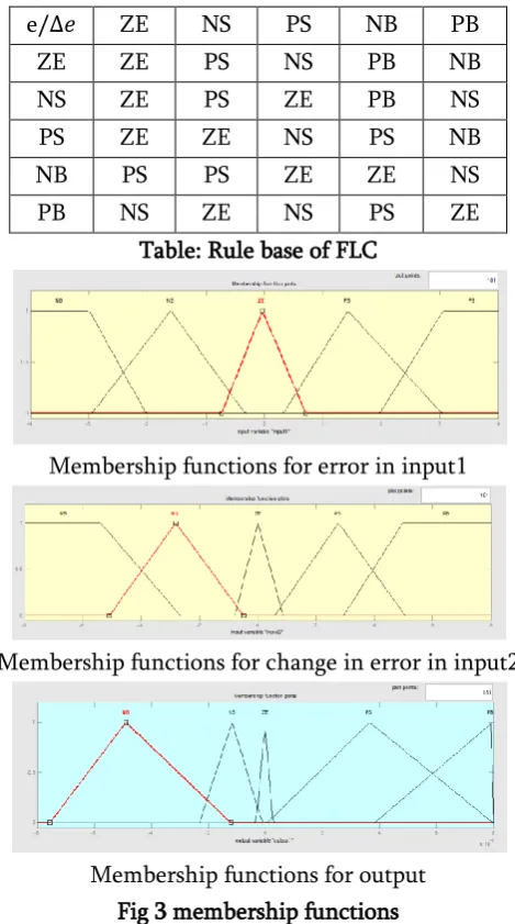
The five variables of the FLC, the error, the change in error and the output, have five triangle membership functions for each. The basic fuzzy sets of membership functions for the variables are as shown in the Figs. 1 and 2. The fuzzy variables are expressed by linguistic variables „positive large (PL) ‟, positive small (PS) ‟, „zero (Z) ‟, „negative small (NS)
‟„negative large (NL) ‟, for all three variables. A rule
in the rule base can be expressed in the form: If (e is NL) and (de is NL), then (cd is NL). The rules are set based upon the knowledge of the system and the working of the system. The rule base adjusts the duty cycle for the PWM of the inverter according to the changes in the input of the FLC. The number of rules can be set as desired. The numbers of rules are 25 for the five membership functions of the error and the change in error (inputs of the FLC).
e ZE NS PS NB PB
ZE ZE PS NS PB NB
NS ZE PS ZE PB NS
PS ZE ZE NS PS NB
NB PS PS ZE ZE NS
PB NS ZE NS PS ZE
Table: Rule base of FLC
Membership functions for error in input1
Membership functions for change in error in input2
Membership functions for output Fig 3 membership functions
IV.
SIMULATION RESULTS
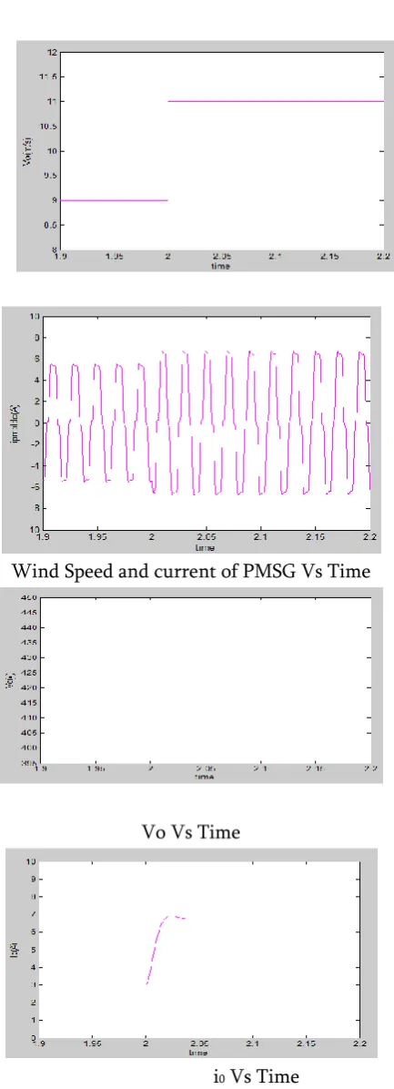
Wind Speed and current of PMSG Vs Time
Vo Vs Time
i0 Vs Time
The wind speed s decreases form 9 m/s to 11 m/s, as needs be PMSG generator yield additionally increments as far as iPMSG. This expansion in power
likewise expands the yield current (I0) and yield
control (P0) of the boost converter.
P0 Vs Time
Fig. 4 MPPT’ performance under wind variation
(a) ILa vs time
(b)ILb vs time
(c) ILc vs time
2.95 3 3.05 3.1 3.15
-20 -10 0 10 20
IL
a
(A
)
time
2.95 3 3.05 3.1 3.15
-20 -10 0 10 20
IL
b
(A
)
time
2.95 3 3.05 3.1 3.15
-20 -10 0 10 20
IL
c(
A
)
time
2.95 3 3.05 3.1 3.15
0 2 4 6 8 10
W
p
t
(d) Wpt vs time
(e) Wqt vs time
(f)Wqv vs time
(g)Wps vs time
(h)Wqs vs time
(i) Isabc vs time
(j) IPa vs time
(k) Ipal vs time
(l)Iqal vs time
(m) Xpa vs time
(n) Xqa vs time
(o) Wpbl vs time
2.95 3 3.05 3.1 3.15
0 0.5 1 1.5 2 2.5 3 W q t time
2.95 3 3.05 3.1 3.15
-20 -10 0 10 20 W q v time
2.95 3 3.05 3.1 3.15
0 5 10 15 W p s time
2.95 3 3.05 3.1 3.15
-10 -5 0 5 W q s time
2.95 3 3.05 3.1 3.15
-20 -10 0 10 20 isa b c* (A ) time
2.95 3 3.05 3.1 3.15
-50 0 50 ilp a time
2.95 3 3.05 3.1 3.15
-20 -10 0 10 20 30 40 ip a l time
2.95 3 3.05 3.1 3.15
0 1 2 3 4 5 iq a l time
2.95 3 3.05 3.1 3.15
0 0.5 1 1.5 2 2.5 3 xp a time
2.95 3 3.05 3.1 3.15
0 0.5 1 1.5 2 2.5 3 xq a time
2.95 3 3.05 3.1 3.15
(p) Wqbl vs time
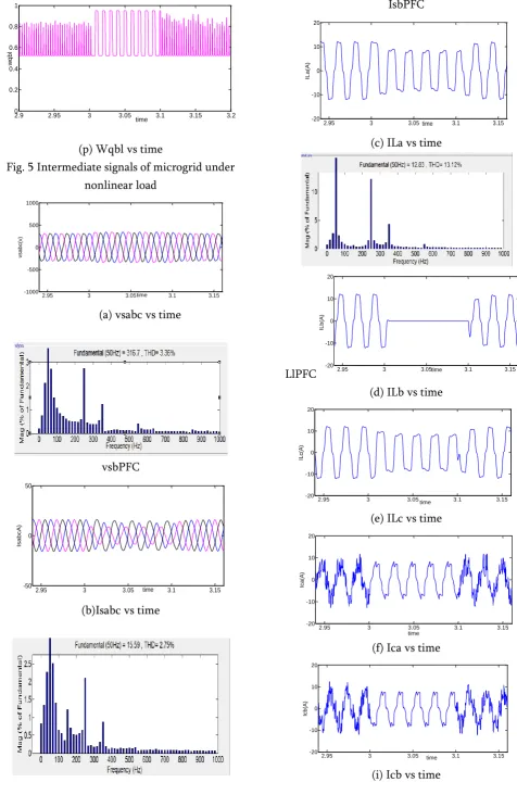
Fig. 5 Intermediate signals of microgrid under nonlinear load
(a) vsabc vs time
vsbPFC
(b)Isabc vs time
IsbPFC
(c) ILa vs time
LlPFC
(d) ILb vs time
(e) ILc vs time
(f) Ica vs time
(i) Icb vs time
2.9 2.95 3 3.05 3.1 3.15 3.2
0 0.2 0.4 0.6 0.8 1 w q b l time
2.95 3 3.05 3.1 3.15
-1000 -500 0 500 1000 vsa b c( v) time
2.95 3 3.05 3.1 3.15
-50 0 50 Isa b cA ) time
2.95 3 3.05 3.1 3.15
-20 -10 0 10 20 IL a (A ) time
2.95 3 3.05 3.1 3.15
-20 -10 0 10 20 IL b (A ) time
2.95 3 3.05 3.1 3.15
-20 -10 0 10 20 IL c( A ) time
2.95 3 3.05 3.1 3.15
-20 -10 0 10 20 Ica (A ) time
2.95 3 3.05 3.1 3.15
(j) Icc vs time
(k) vt vs time
(l) vt vs time
(m) ib vs time
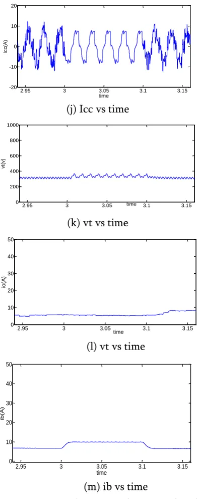
Fig.6 Dynamic performance of microgrid under nonlinear load
Simulation results with FUZZY Controller
MPPT performance of the boost converter is depicted in Fig. 4. The wind speed varies from 9 m/s to 11 m/s, 0093- accordingly PMBLDC generator output also increases in terms of iPMBLDCG. This increase in power also increases the output current (Io) and output power (Po) of the boost converter. The DC
link voltage is maintained constant at 400V by the battery bank.
(a) Wind Speed and current of PMSG Vs Time
(b)vo and Io vs Time
(c) po vs time
Fig. 7 MPPT’ performance under wind variation
(a).load currents vs time
2.95 3 3.05 3.1 3.15
-20 -10 0 10 20
Icc(
A
)
time
2.95 3 3.05 3.1 3.15
0 200 400 600 800 1000
vt(
v)
time
2.95 3 3.05 3.1 3.15
0 10 20 30 40 50
io
(A
)
time
2.95 3 3.05 3.1 3.15
0 10 20 30 40 50
ib
(A
)
(b)
(c)
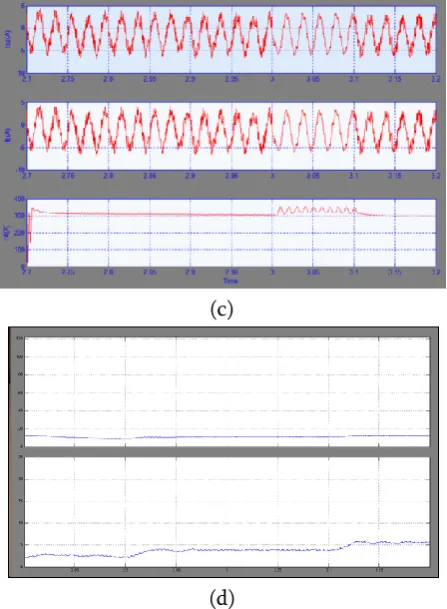
Fig.8 Dynamic performance of micro grid under nonlinear load
Fig 5(a) Fig. 5 depicts the intermediate signals of the microgrid control under nonlinear loads during load unbalancing. With load variation (iLb) at t=3s, the PCC voltages (vsabc) and source currents (isabc) are maintained sinusoidal The intermediate signals ILpb
(aggregation function of input layer for active power component of load current), Ipbl (aggregation function for active component of hidden layer), Iqbl (aggregation function for reactive component of hidden layer), Xpb (active component of output of input layer neuron), and Xqb (reactive component of output of input layer neuron) change their values according to the control requirement. Active and reactive power components of load currents (wpbl, wqbl), average active and reactive power components of load currents (wpt, wqt), weighted value of output of PI controller to regulate terminal voltage (wqv) show changes with load variation. Active and reactive power components of reference input currents (wps, wqs) are also depicted. The reference currents (i*sabc) are sinusoidal throughout the change
(a)
(c)
(d)
Fig.9 Intermediate signals of micro grid under nonlinear load
Fig 6(b) The dynamic conditions are realized by disconnecting the load at phase ‘b’ at t= 3s and again the balanced load is created at t= 3.1s by connecting the load. At unbalanced condition in Fig.6, when phase ‘b’ current (iLb) is zero and the other two phases are with unbalanced currents (iLa, iLc), the performance of control algorithm is clearly seen that the PCC voltage (vsabc) is maintained constant and the input currents (isabc) are also sinusoidal during contingency. The compensating currents (ica, icb, icc) are changed according to the requirement of reactive power compensation to maintain the terminal voltage (Vt) near the reference value. It is shown that during dynamic condition when the load is reduced, the excess power coming from the DG which is working as constant power generator, is stored in BSS in terms of charging current (Ibt) with constant power generation from WECS as Io shown in Fig.6
Fig 10 (a) Figs.10 (a-c) show the steady state performance of algorithm in terms of line voltage vsab, input current isb and load current iLb. Results justify the performance of algorithm as the voltage and input currents are under the distortion limit of 5% while the load currents are distorted above 20%.
Fig 10(b)
Fig 10 (c)
Fig.10 Dynamic performance of micro grid under nonlinear load
V.
CONCLUSION
Its trapezoidal EMF has helped to convert AC power into DC power using 3-phase rectifier with less ripples and has given an economic solution for WECS by replacing one VSC with a diode bridge rectifier. BPFF algorithm for VFC has provided harmonics elimination of the supply, voltage regulation, load leveling. MPPT controller has extracted maximum power using a boost converter and feeds to the battery and loads. During low wind conditions, battery and DG take care of load demand. A comparison of simulated results is made to show the accuracy of the BPFF control algorithm. The steady state error and THD are reduced by using the Fuzzy logic controller.
VI.
REFERENCES
[1]. M. Hook, A. Sivertsson, and K. Aleklett,"alidity of the fossil fuel production outlooks in the IPCC Emission Scenarios" Natural Resources Research, vol. 19, no. 2, pp. 63-81, June 2010. [2]. F. Mushtaq, W. Maqbool, R. Mat, and F.N. Ani,
"Fossil fuel energy scenario in Malaysia- prospect of indigenous renewable biomass and coal resources," in proc. of IEEE Conference on Clean Energy and Technology (CEAT), 2013, 18-20 Nov. 2013, pp.232-237.
[3]. N. Bauer, I. Mouratiadou, G. Luderer, Lavinia Baumstark, R. J. Brecha, Ottmar Edenhofer, and Elmar Kriegler, "Global fossil energy markets and climate change mitigation – an analysis with REMIND" Springer, Oct, 2013.
[4]. Bin Wu, Y. Lang, N. Zargari, and S. Kouro, "Power Conversion and Control of Wind Energy Systems", John Wiley & Sons, Inc., Hoboken, New Jersey, 2011.
[5]. Gilburt M. Master, "Renewable and Efficient Electric Power Systems", John Wiley & Sons, Inc., Hoboken, New Jersey, 2004.
[6]. K.F. Krommydas, and A.T. Alexandridis, "Modular Control Design and Stability Analysis of Isolated PV-Source/Battery-Storage Distributed Gengenerationtion Systems," IEEE Journal on Emerging and Selected Topics in
Circuits and Systems, vol.5, no.3, pp.372-382, Sept. 2015.
[7]. A. Elmitwally, and M. Rashed, "Flexible Operation Strategy for an Isolated PV-Diesel Microgrid Without Energy Storage," IEEE Trans. on Energy Conversion, vol.26, no.1, pp.235-244, March 2011.
[8]. Miao Zhixin, A. Domijan, and Fan Lingling, "Investigation of Microgrids With Both Inverter Interfaced and Direct AC-Connected Distributed Energy Resources," IEEE Transactions on Power Delivery, vol.26, no.3, pp.1634-1642, July 2011.
[9]. M. Arriaga, C.A. Canizares, and M. Kazgenerationni, "Renewable Energy Alternatives for Remote Communities in Northern Ontario, Canada," IEEE Trans. on Sustainable Energy, vol.4, no.3, pp.661-670, July 2013.
[10]. Dong-Jing Lee and Li Wang, "Small-Signal Stability Analysis of an Autonomous Hybrid
Renewable Energy Power
Gengenerationtion/Energy Storage System Part I: Time-Domain Simulations," IEEE Trans. on Energy Conversion, vol.23, no.1, pp.311-320, March 2008
Author’s Profile:
Y. Sunil Kumar Reddy received B.Tech degree in Electrical and Electronics Engineering from VBCE, Hyderabad and currently Studying Post Graduation in Power Electronics and Drives from CREC, Tirupati, Andhra Pradesh, India.