321 |
P a g e
IMPLEMENTATION OF DIGITAL MODULATION
TECHNIQUES IN MATLAB
Virendrakumar V. Raut
Jagadambha College of Engg. & Techno. Yavatmal.(India)
ABSTRACT
As concern with telecommunication engineering, we studied about digital modulation technique. Different type
of modulation technique use transmitting and receiving massage signal at RF frequencies. All type of signal in
air is analog in nature, so we have to analysis that signal. by using matlab tool, here we are implement the
different type of modulation technique along with their mathematical representation. In this paper we are
implementing different type of modulation technique such as massage signal which is binary in nature they lies
on carrier frequency. Means that massage signal travels with carrier frequencies that is in analog mature. So,
we have to analysis carrier frequency parameter like amplitude, phase, and carrier frequency varied according
with massage signal or baseband signal. Simulation frame work operation act as like real world operation over
time. That’s reason we implement simulation in matlab, to help as real world characteristics.
In this paper we are implementing the binary phase shift keying (BPSK), quadrature phase shift keying (QPSK),
and amplitude shift keying (ASK), frequency shiftKeying (FSK)in matlab by using different Simulink tool boxes.
Keywords: Digital Modulation, Simulation, ASK, FSK, QPSK, BPSK.
I. INTRODUCION
Modulation is defined process by which some characteristics of carrier signal varied according with modulating
signal. Here characteristics of carrier signal like phase, angle, amplitude and frequency. And the modulating
signal means the massage signal which in binary form. Digital modulation techniques, consider digital to analog
conversion. And the demodulation or detection analog to digital conversion. The modulation of digital signal
information can be transmitted by using cable, microwave system, satellite at different frequencies. As per practical implement approach several type of delay, noise in analogous waveform which is transmitted. All
type of modulation techniques, as concern with practical approach considering baseband signal and carrier
frequency.
Type of modulation technique classified as following.
1. Binary phase shift keying (BPSK)
2. Quadrature phase shift keying (QPSK)
3. Amplitude shift keying (ASK)
4. Frequency shift keying (FSK)
These are some technique which can be implemented in matlab before implementing of these, firstly
322 |
P a g e
IIMODULATION& DEMODULATION TECHNIQUES
2.1
Binary Phase Shift Keying (BPSK)
(a)
BPSK Modulation
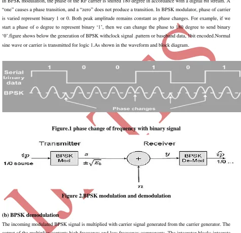
In BPSK modulation, the phase of the RF carrier is shifted 180 degree in accordance with a digital bit stream. A
“one” causes a phase transition, and a “zero” does not produce a transition. In BPSK modulator, phase of carrier
is varied represent binary 1 or 0. Both peak amplitude remains constant as phase changes. For example, if we
start a phase of o degree to represent binary „1‟, then we can change the phase to 180 degree to send binary
„0‟.figure shows below the generation of BPSK withclock signal .pattern or baseband data, 1bit encoded.Normal
sine wave or carrier is transmitted for logic 1.As shown in the waveform and block diagram.
Figure.1 phase change of frequency with binary signal
Figure 2.BPSK modulation and demodulation
(b) BPSK demodulation
The incoming modulated BPSK signal is multiplied with carrier signal generated from the carrier generator. The
output of the multiplier contents high frequency and low frequency components. The integrator blocks integrate
multiplier output. With help of comparator by comparing threshold values input data is received.
2.2 Quadrature Phase Shift Keying (QPSK)
a) QPSK modulation
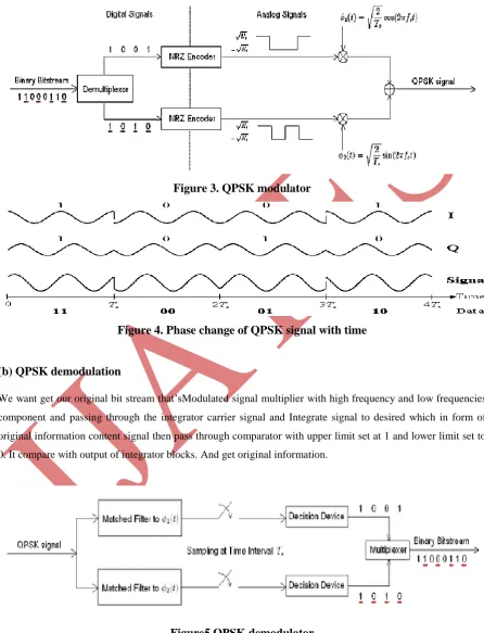
The binary bit stream or massage signal is pass through line coding like bipolar NRZ signal represent at binary
323 |
P a g e
information bit stream. Phase can be changes accordance with binary bit 1 and 0 respectively such waymodulation signal is phase changes shown in figure3.
Figure 3. QPSK modulator
Figure 4. Phase change of QPSK signal with time
(b) QPSK demodulation
We want get our original bit stream that‟sModulated signal multiplier with high frequency and low frequencies
component and passing through the integrator carrier signal and Integrate signal to desired which in form of
original information content signal then pass through comparator with upper limit set at 1 and lower limit set to
0. It compare with output of integrator blocks. And get original information.
324 |
P a g e
2.3 Amplitude shift keying (ASK)
a) ASK modulator
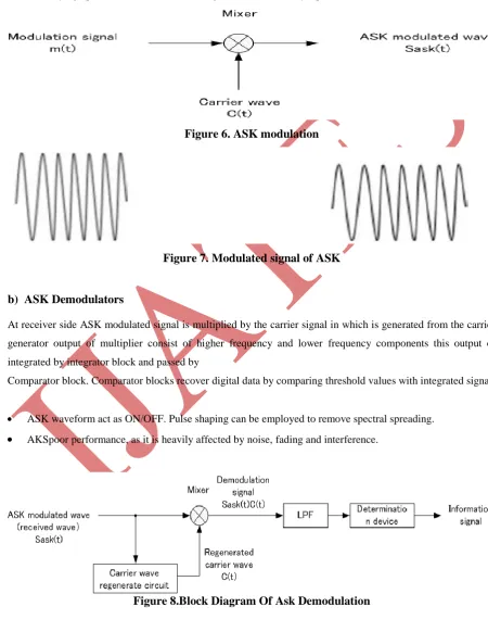
In ASK modulator level of amplitude can be used to represent binary logic 0s and 1s.Wecan think of carrier
signal as an ON or OFFSwitch. In modulated signal logic 0 is represented by the absence of carrier, thus giving
OFF/ON keying operation and hence the name given mathematically equation of ASK.
Figure 6. ASK modulation
Figure 7. Modulated signal of ASK
b) ASK Demodulators
At receiver side ASK modulated signal is multiplied by the carrier signal in which is generated from the carrier
generator output of multiplier consist of higher frequency and lower frequency components this output of
integrated by integrator block and passed by
Comparator block. Comparator blocks recover digital data by comparing threshold values with integrated signal.
ASK waveform act as ON/OFF. Pulse shaping can be employed to remove spectral spreading.
AKSpoor performance, as it is heavily affected by noise, fading and interference.325 |
P a g e
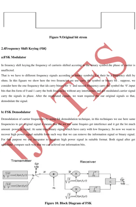
Figure 9.Original bit strem
2.4Frequency Shift Keying (FSK)
a)FSK Modulator
In freuency shift keying,the frequency of carrieris shifted accoring to the binary symbol.the phase of carrier is
unaffected.
That is we have to different frequency signals according to binary symbols. Let their be a frequency shift by
ohms. In this figuare we show here the two freuencies are use carry the symbol or binary bit . suppose, we
consider here the one frequency that ids carry binary bit „1‟ and second frequency carry the symbol the „0‟.input
bits that ibn form of 0 and 1 carry the both freqiencies without any interfaernce and get modulated.carrier signal
carry the signals in phase. After the modulated signals, we want required the our original signals so that,
demodulate the signal.
b) FSK Demodulator
Demodulation of carrier frequencies by using fsk demodulation technique, in this techniques we use here same
frequencies to get original signal it means that the we use same frequies get interfernce and it get the lot much
amount power in signal. At same time binary signal which have carry with low frequency. So now we want to
recover high power signal suitable form such way that we can remove the information signal or binary signal.
For that purpose we use integrator to integrate high power signal in suitable format. Both signal after get
addedand compare such way that we can achived our information bits.
326 |
P a g e
III. IMPLEMENTATION OF MODULATION TECHNIQUE IN MATLAB
3.1 BPSK module
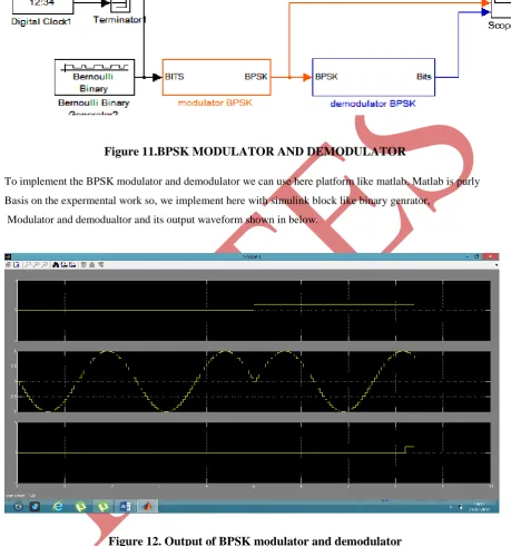
Figure 11.BPSK MODULATOR AND DEMODULATOR
To implement the BPSK modulator and demodulator we can use here platform like matlab. Matlab is purly
Basis on the expermental work so, we implement here with simulink block like binary genrator,
Modulator and demodualtor and its output waveform shown in below.
Figure 12. Output of BPSK modulator and demodulator
We are showing above output waveform of output of modulator and demodulator in scope. Scope having the 3
axis respectively. So the binary bits or information bits on 1 axis after that the modulated waveform of BPSK
shown in second axis and finally shows demodulated data means our information bits are reception. But
problem is that some delay occurs due to system because of system have not hundred percentage performance
327 |
P a g e
3.2 QPSK module
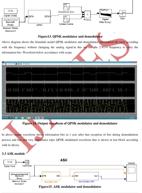
Figure13. QPSK modulator and demodulator
Above diagram shows the Simulink model QPSK modulator and demodulator information bit carry according
with the frequency without changing the analog signal.in this we use the 2*Pi*4 frequency to carry the
information bits. Waveform below accordance with scope.
Figure 14. Output waveform of QPSK modulator and demodulator
In above output waveform shows information bits in 1 axis after that reception of bits during demodulation
process and last and very importance topic QPSK modulated waveform that is shown in last block according
with its theory
3.3 ASK module
328 |
P a g e
In above figure amplitude shift keying the data can be vary accordance with amplitude of desirable signal. Atsame moment binary signal can changes accordance with frequency which is given.as per as concern with ASK
the bandwidth of signal is minimum so that we goes the above techniques. Like BPSK, QPSK. In this system
the reception of signal having delay and having possibly error occurs in sequences of bit. Its better system but in
long communication it fails to communicate.
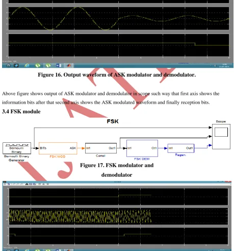
Figure 16. Output waveform of ASK modulator and demodulator.
Above figure shows output of ASK modulator and demodulator in scope such way that first axis shows the
information bits after that second axis shows the ASK modulated waveform and finally reception bits.
3.4 FSK module
Figure 17. FSK modulator and
demodulator
329 |
P a g e
In above diagram shows implementation of FSK in matlab and output shows below implementation FSKMODULE, it show information bit on 1st axis, 2nd axis shows the modulated waveform of FSK and last axis
shows reception bits having some delay.
IV RESULTS
As concern with digital modulation techniques, we can implement the basics digital modulation techniques with
help of theoretical concept. But after analysis with theoretical concept, we observed that experimentally
reception bits having some delay. So, by using these observations we can calculate these delay.
V CONCLUSION
If we change parameter of system we can observed different operating signal. Because, we can made these
Simulink model in matlab .so, we can observed and calculate delay, power spectral density, noise. If
suppose we implement spectrum analyser with these a system, we can easily calculate all these things.
REFERENCE
[1] Advanced Electronic Communications Systems (Fifth Edition); Tomasi, Wayne;Prentice-Hall, Inc.: Upper
Saddle River, New Jersey 2001; pp. 47.
[2] W. Dai, Y. Wang, J. Wang, Joint power estimation and modulation classification using second and higher
statistics, WCNC 2002 - IEEE Wireless Communications and Networking Conference, No. 1, 2002, pp. 767
– 770.
[3] L. Hong, K. C. Ho, Identification of digital Modulation types using the wavelet transform, MILCOM 1999 –
IEEE Military Communications Conference, No. 1, 1999, pp. 427 – 431.
[4] L. Hong, K. C. Ho, BPSK and QPSK modulation Classification with unknown signal levels, MILCOM 2000
- IEEE Military Communications Conference, No. 2, 2000, pp. 976-980.
[5] F. Liedtke, Computer simulation of an automatic Classification procedure for digitally modulated
Communication signals with unknown parameters, Signal Processing, 1984, Vol. 6, No. 4, pp. 311–323.
[6] L. Chaari, M. Fourati, N. Masmoudi, L. Kamoun, An adaptive Coded Modulation with Multi-Levels QoS
Analysis in Multimedia Environment, WSEASTransactions on Communications, 2009, Issue 6,Vol. 8.
[7] Communication System, Symon Haykin, John wiley & sons.
[8] Wireless communications, Rappaport, Theodore, PHI publication,2002.
[9] CDMA -overview, from internet at: http://en.wikipedia.org/wiki/Code_division_multiple_access
[10] “Comparison of modulation and detection techniques for CDMA cellular system” by Michael Xiaolong Li,
B.E. Tsinghua University, 1990, Beijing, China.
[11] De Fina, S. ; Lombardo, P.; “Error probability analysis for CDMA systems with closed loop power control”