EFFICIENT IMPLEMENTATION OF MULTI MODAL
BIOMETRIC PATTERN RECOGNITION USING
SUPERVISED NEURAL NETWORK
S.Hariprasath
1M.Santhi
2 1Assistant Professor, Dept of ECE, Saranathan College of Engineering, Trichy India)
2
Professor, Dept of ECE, Saranathan College of Engineering, Trichy (India)
ABSTRACT
A Biometric system is essentially a pattern recognition system that makes use of biometric traits to recognize
individuals. Authentication systems built on only one biometric modality may not fulfill the requirements of
demanding applications in terms of properties such as performance, acceptability and distinctiveness. Most of
the uni-modal biometrics systems have problems such as noise in collected data, intra-class variations,
inter-class variations etc. Some of these limitations can be overcome by using multiple source of information for
establishing identity; such systems are known as multimodal biometric systems. In this paper a multi modal
biometric system of iris and palm print based on Wavelet Packet Analysis and a neural classifier implemented in
FPGA is described. The most unique phenotypic feature visible in a person’s face is the detailed texture of each eye’s iris. Palmprint is referred to principal lines, wrinkles and ridges on the palm. The visible texture of a person’s iris and palm print is encoded into a compact sequence of 2-D wavelet packet coefficients, which generate a “feature vector code”. In this paper, a novel multi-resolution approach based on Wavelet Packet
Transform (WPT) for texture analysis and recognition of iris and palmprint is proposed. With an adaptive
threshold, WPT sub images coefficients are quantized into 1, 0 or -1 as biometric signature. By using wavelet
packets the size of the biometric signature of code attained is 10240 bits. The combined pattern vector of palm
print features and iris features are formed using fusion at feature level and applied to the pattern classifier. The
LVQ neural network which is used as pattern classifier produces better recognition rate of 91.22%.The neural
network is implemented for input vector of 10 featuresand 12 input classes and 8 output classes, using virtex-4
xc4vlx15 device. This system can complete recognition in 5.25 micro seconds thus enabling it being suitable for
real time pattern recognition tasks.
Keywords
—Biometric Fusion, FPGA Implementation, LVQ, Multi Modal Biometric
I.
INTRODUCTION
324 | P a g e database to either verify a claimed identity or determine the individual's identity. The performance of an automated biometric authentication system is typically gauged by measuring the trade-off between the false accept rate (FAR) and the false reject rate (FRR). For a given system, it is not possible to reduce these two error ratessimultaneously. A promising approach to significantly decrease these two error rates is to employ more than one biometric system with each system generating its own decision about an individual's identity (or claimed identity). Such systems, known as multibiometricsystems [1], reconcile the information presented by multiplesub-systems. WhenNindependently constructed sub-systems function together, theNoutput scores can be consolidated into a singleoutput. This is the problem ofscore-level fusion which is the mostpopular fusion approach due to the ease of accessing scores fromcommercial matchers. Most multibiometric systems described in theliterature employ a common fusion mechanism for all users. In this paper we have followed feature level fusion by combining the pattern vectors extracted from iris and palm print data. The feature vectors are extracted by computing texture features from iris and palm print image with the help of gray level co-occurrence matrix and combined to form a single pattern vector.
Common algorithms for processing and classification of signals in pattern recognition may require a reasonable computational power, which cannot be achieved using microprocessors commonly used in embedded systems. An alternative for the development of embedded systems that require high processing power is the hardware implementation of software algorithms using Field Programmable Gate Arrays (FPGAs). These devices can be programmed for a given functionality. In contrast to the common microprocessors that run software instructions sequentially in a predefined architecture, FPGAs have their internal structure defined by the designer, allowing the customization of both the architecture and the functionalities of the system for a given purpose. The possibility of design of many blocks which operate in parallel is one of the most outstanding features of such reconfigurable devices thereby increasing the processing power of the system. In recent times FPGAs are becoming very popular due to cost and flexibility. Due to its availability and performance, FPGAs have been used in powerful reconfigurable systems. Therefore, systems based on reconfigurable hardware can offer custom-computing machines for specific applications, with orders of magnitude faster than regular software processing in general-purpose processors [2].
The objective of this work is to propose a methodology for the implementation of a Learning Vector Quantization (LVQ)Neural Network (NN) as classifier for pattern recognition of palm print and iris data using a reconfigurable device. LVQNNs are frequently used for pattern recognition ([4],[5]), and are particularly very interesting for hardwareimplementation since they are based on the calculation ofa geometric distance among samples and reference vectors.This feature eliminates the necessity of multipliers that occupy a large amount of resources in reconfigurable components and requireless clock cycles.
II.
EXISTING
METHODS
In order to obtain iris signature, phasors are evaluated and coded by their location in the complex plane. However the Daugman’s method is patented which blocks its further development.
In another approach suggested, by Lye Wil Liam and Ali Chekima in their paper [4], the iris image is pre processed for contrast enhancement. After preprocessing, a ring mask is created and moved through the entire image to obtain the iris data. By using this data the iris and pupil are reconstructed from the original picture. Using the iris center coordinate and radius, the iris was cropped out from the reconstructed image. The iris data (iris donut shape) is transformed into a rectangular shape. Using a self organized feature map the iris pattern is matched.The network contains a single layer of Euclidean weight function. Manhattan Distances are used to calculate the distance from a particular neuron X to the neuron Y in this neighborhood. The Manhattan Distances without a bias and a competitive transfer function is used to upgrade the weight.
In another method followed by Jie Wang [7] the iris texture extraction is performed by applying wavelet packet transform (WPT) using Haar wavelet. The iris image is decomposed in to sub images by applying WPT and suitable sub images are selected and WPT coefficients are encoded.
K.Grabowski and W.Sankowski have designed another method for iris features extraction method. In their paper [8], Haar wavelet based DWT transform is used.
Ajay Kumar and Helen C. Shen [9] proposed an approach in which Gabor filter is used for palm print recognition. Fang Li et al. [10] proposed an approach utilizing Line Edge Map (LEM) of palm print as the feature and Hausdorff distance as the distance matching algorithm.
The content of this paper is organized as follows. Section III describes the steps involved in multimodal Recognition System. Section IV presents our proposed approach using Wavelet packet Transform and LVQ classifier and hardware implementation. Section V gives the results of Wavelet packet Transform based approach on the iris and palm print database and hardware implementation results. Finally, conclusions and perspectives are given in section VI.
III.
BIOMETRIC
FUSION
ANDLVQ
NEURAL NETWORKS 1)Multi Modal Biometric and Fusion of feature vectors326 | P a g e In general, a biometric system comprises of four parts, namely, (i) sensor module – to acquire raw biometric impression(s), (ii) pre-processing and feature extraction module – to enhance the acquired impression(s), and to extract salient characteristics from them, (iii) matcher module – to compare the query features with the stored template in order to produce a match score, (iv) decision module – to authenticate or reject a user by comparing the match score against a predefined threshold.
In a multimodal biometric system, each subsystem provides an opinion or a decision on the user’s claim. The supervisor module uses different fusion strategies to combine each subsystem opinion or decision and make a final decision. Fusion can use multiple representations of a single biometric, a single biometric with multiple matchers or multiple biometric identifiers. Fusion can be performed at different levels: sensor level, feature level, confidence level and abstract level. In this paper feature level fusion technique is used to combine the features extracted from iris and palm print data. Figure.1 shows the block diagram of multimodal biometric system using feature leave fusion. For computing the feature vector for combined multimodal system, individually the features are extracted using a feature extractor. If the same feature extractor algorithm is used then the system is called single algorithm based multi modal system[11]. In our implementation we have used wavelet packet transformfollowed by GLCM Unit as extractor to extract the features for creating feature vector. The block diagram of a pattern recognition system is shown in figure 2. The input biometric is collected by the sensor. Using the pre processing unit, the data is converted into suitable form that is applied to feature extractor. In our system wavelet packets s used to extract the features from iris image and Gabor filter from palm print image. The extracted image features are applied to GLCM calculator which computes the textural features. As both iris image and palm print are rich with textural information, the co occurrence matrix computed is also rich in features which adequately describe the biometric input. A set of 12 features from iris and a set of 6 features from palm print are computed and both the sets are concatenated to produce a multi modal pattern vector of size 18 and applied to LVQ neural network. The pattern vector formation is completed using Matlab [12] tool and the resultant pattern vectors are stored in a text file from which the FPGA module of LVQ neural network reads the input vectors.
.
Figure1.Multi Modal Biometric System using feature level fusion
FE Palm Sensor
Iris Sensor FE
MM Templates
FM DM
IV.
MULTI
MODAL
BIOMETRIC
SYSTEM
In this particular approach, the iris images are encoded using wavelet packets to formulate a template. The palm print images are encoded using Gabor wavelets. The features are then combined into a multi modal pattern vectorof dimension 18 and applied to LVQ classifier.
4.1
Multi modal biometric system
i.
Iris Recognition System
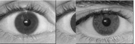
An iris recognition system can be decomposed into three modules: an iris detector for detection and location of iris image, a feature extractor to extract the features and a pattern matching module for matching. The iris is to be extracted from the acquired image of the whole eye. Therefore, before performing iris pattern matching, the iris is to be localized and extracted from the acquired image.
a)Iris Localization
The first step is iris localization. Using the Integrao Differential Operator (IDO) (1) the iris is localized.
( , 0, 0)
, 0, 0
( , )
max
*
2
r x y
r x y
I x y
G
ds
r
r
where
I x y
( , )
is a raw input image. The IDO (1) suggested by J.Daughman [1][2] searches over the image domain( , )
x y
for the maximum in the blurred partial derivative with respect to increasing radiusr
, of the normalized contour integral ofI x y
( , )
along a circular arcds
of radiusr
and center coordinates( 0, 0)
x
y
.The symbol
denotes convolution andG r
( )
is a smoothing function such as a Gaussian of scale
. This operator actually behaves as a circular edge detector, blurred at a scale
. It searches iteratively for the maximal contour integral derivative at successively finer scales of analysis through the three-parameter space( 0, 0, )
x
y
r
defining a path of contour integration. It finds both pupillary boundary and the outer boundary of the iris. The results are shown in figures 2to 5.Figure 2. Iris Image 1 Figure 3. Iris Image 2Figure 4. localisation of iris image1 Figure 5. Localisation of Image 2
b)
Iris Normalization
328 | P a g e
( )
*sin( )
x
c x
r
( )
*cos( )
y
c y
r
where
c x y
( , )
denotes center coordinates,( , )
x y
denotescoordinates of the image,
is the angle andr
denotes the radius. Figure6 and 7 shows the extracted (normalized) iris data.Figure 6. Normalized data (Extracted Iris data) of Iris image 1Figure 7. Normalized data (
Extracted Iris data) of Iris image 2
c)
Wavelet Packet Transform (WPT Approach)
The standard discrete wavelet transform (DWT) is a very powerful tool used successfully to solve various problems in signal and image processing. The DWT breaks an image down into four sub-sampled images. The results consist of one image that has been high passed in the horizontal and vertical directions (HH), one that has been low passed in the vertical and high passed in the horizontal (LH), one that has been high passed in the vertical and low passed in the horizontal (HL) and last that has been low pass filtered in both directions (LL) Where, H and L mean the high pass and low pass filter, respectively. While HH means that the high pass filter is applied to signals of both directions, represent diagonal features of the image, HL correspond to horizontal structures, LH correspond to vertical information and LL is used for further processing.
Wavelet Packets Transform (WPT) is a generalization of Wavelet Transform that offers a richer signal analysis. With WPT, it is possible to zoom into any desired frequency channels for furtherdecomposition.Compared with WT, WPT offers a finer decomposition.When processing some oscillating signals, partition of lowfrequency parts is not fine enough. WPT can overcome thisproblem via decomposing high frequency components andmore details obtained in WPT yield better representation ofsignals. As a progressive texture classification algorithm,WPT gives reasonably better performancebecause thedominant frequencies of iris texture are located in the lowand middle frequency channels.
Biometric texture extraction with WPT andencoding procedureinvolves three steps:
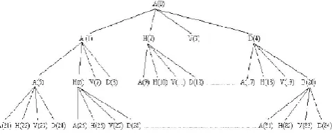
1.Decomposition. At each stage in the decompositionpart of a 2-D WPT, four output subimages are
generated.The imagescontain approximation (A), horizontal detail (H),vertical detail (V) and diagonal detail (D) coefficientsrespectively. After 3-level WPT, an image has a quadtreewith 64 output subimages, each representing differentfrequency channels [11].It is shown in Figure 8.
2.Selection of sub images for feature encoding
choose asubset of all possible subimages to make our encode process. The useful subimages with entropy criterion tomake our analysis much more efficient and just as accurate using (3).
2 2
,
log(
,)
i j i j i j
Entropy
S
S
In equation (3)
S
i j, is the coefficient of the sub image. It is found that sub-image 10 retains higher entropy than other sub images. Hence it is chosen as the candidate sub-image for feature extraction.3.Iris Feature encoding
A code matrix can be achieved by quantizing the coefficients of candidate sub-image and LL3, HL3 or LH3 into one data element each with a suitable threshold T as shown in equation (4).
1
ij
C
ifS
ij>T
;C
ij
0
, |S
ij | <T
;C
ij
1
,ij
S
< -T; (4)where
S
ij is the coefficient of a sub-image,C
ijis the corresponding code element andT
is Threshold is a positive number.Equation (4) has 2 abilities of de-noising and finding singular points.T
is chosen as3
T
and
is the variance of the noise. It is reported that the Standard Deviation of the WPT high frequency coefficients (sub -image 84) are having the good estimation of
. The code matrix gives a good description of both frequency and location content of an image. The chosen sub image is called candidate sub-image.Figure 8. Wavelet packet decomposition
ii.
Palm print Recognition System
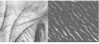
Before feature extraction, it is necessary to obtain a sub-image from the captured palmprint image and to eliminate the variations caused by rotation and translation. After extracting the sub image as region of extraction by pre-processing, the texture features of the palm prints are extracted by Gabor filters decomposition scheme. The Gabor filter is an effective tool for texture analysis and has the following general form.
2 2
1
( , , , , ) 2exp 2 exp(2 )( cos sin )
2 2
x y
G x y i x y
330 | P a g e where i = -1, u is the frequency of the sinusoidal wave, q controls the orientation of the function and s is the standard deviation of the Gaussian envelope. The sample point in the filtered image as shown in Fig. 9 is coded in to two bits (br, bi) . Depending on the phase value of complex vector generated, using table 1 phase bits are generated. Thus palm print code of 960 bits is generated.
Figure 9. Preprocessed pal m print and extracted palm print features
In our implementation we have used wavelet packet transform and gabor filter which captures the iris data and palm print data respectively. The GLCM calculations which are originally proposed by Haralick [13] are used to capture the texture information from transformed data. The best candidate sub image from wavelet packet transform and gabor sub images are chosen and haralick features are computed. From the Haralick features computed for each biometric, 12 iris features and 6 palm print features are combined to produce a pattern vector of dimension 18.The features are listed in table 4. The multi modal pattern vector which is of dimension 10 is used to train the LVQ classifier.
A. LVQ Neural Networks
The LVQ Neural Network (LVQ NN) is a method for training neural networks for pattern classification. In this method each output represents a particular class. Each class is referred by a weight vector which represents the center of the clusters defining the decision hypersurfaces of the classes. A given class can be defined by a single point or a set of classes, for a better representation of irregular decision surfaces. For training this NN it is necessary to have a set of training patterns with known classes and an initial distribution of the reference vectors. During training, each input sample x is taken along with its cluster center W (which is nearer to the input x). The known class T of input sample x and the class C represented by the cluster center w is compared. The center of the cluster w is updated according to equation 7, where α= alpha is the learning rate of the NN.
T= c
w
.
T
c
w
.
new prev prev
new prev prev
if
then
w
x
w
if
then
w
x
w
………. (7)Training is done for all input variables several times, always taken them in a random order. Usually, training is concluded when clusters get stable, or either a previously specified number of iterations is reached. Basically, after being trained, a LVQ NN becomes a vector comparator. Every new input will be assigned to a class which cluster center is the most similar to it. The similarity (or dissimilarity) measure of two generic points x and y can be implemented as the geometric distance between them. A general distance norm is given by equation 8, where n is the dimensionality of the space and wi a weighting coefficient.
becomes a vector comparator. Whenvever a new input is presented to the nn, it is assigned to a class whose cluster centre is most similar to the input. The similarity (or dissimilarity) measure of two generic points x and y can be implemented as the geometric distance between them.By For certain applications which require faster computation, Manhattan distance which is shown in equation 8 is used as similarity measure.
1
( , )
.
n
i i i i
d x y
w x
y
………..(8)B. Hardware implementation
The general implementation of neural networks in FPGA is reported in many works in the literature [14], [15]. In most of such works, the particular type of NN and its implementation is not discussed and instead general implementation is described. Better results can be achieved when the architecture particular to a specific NN is focused and implemented [16]. In this work, the implementation of LVQ NN for input pattern of dimension size 10 (pattern vector of 10 features are combined viz 6 features from iris data and 4features from palm print data) and output class of size 3 are considered. The subclasses considered are 6 in size. From a pool of 60 iris and 60 palm print images (belonging to 12 iris class and 12 palm print class), 90 pattern vectors are used for training. The remaining 30 pattern vectors of dimension 16 are used for testing the trained NN.
A block of internal ROM memories used to store fixed LVQ weights for the K neurons (K=12). For each neuron j of the LVQ output layer, the Manhattan distance must be computed. The operator
|X
i−W
ij| is implementedby the architecture which is formed with a serial subtractor followed by serial on-line absolute value processor. The global architecture of the distance computation is given in figure 2. The small area of serial operators allows all the computations to be performed simultaneously by means of a column of M subtractors followed by a column of M absolute value processors. It provides M outputs that are connected to the M inputs of a simple tree of serial adders. The new Weights are calculated according to equation 1 and stored in the ROM. A comparator circuit is used to select minimal distance
d
i according to the equation 1 and the corresponding winner neuron isselected. The winner neurons weights are updated using the equation 1.The overall architecture is shown in figure10 and classifier RTL diagram is shown in figure 11.
332 | P a g e
V.
RESULTS
AND
DISCUSSION
The LVQ network architecture includes 10 units on the input layer, which represent the 10 features formed by the concatenation of iris and palm print feature vectors. There are 3 units on the output layer that characterize the one of 9 output classes. After training with 75 % of the input data, testing is performed with the remaining data as described in section IV. The results of recognition in terms of False Acceptance Ratio and False Rejection Ratio are given in the table 1 for Iris and table 2 for palm print and in table 3 for combined recognition.
The device utilization report is shown in table 4.
T
ABLEI.
RECOGNITION PERFORMANCE OF IRIS FEATURE VECTOR USINGDIFFERENT MOTHER WAVELETS
TABLE
III.PERFORMANCE
OF
FEATURE VECTOR FOR MULTI MODAL BIOMETRICModality Accuracy in % Feature vector length
Iris 91.50 960
Palmprint 89.46 960
Combination of
Iris and Palmprint 96.62 960
TABLE
IV.
DEVICE UTILIZATION REPORT SUMMARY FOR VIRTEX4
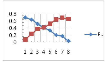
DEVICEThe Performance of the proposed iris recognition system using Symlets and biorthogonal wavelets are shown in the figures 12, 13. In these figures classes refer to the image classes of iris images. Class 1 refers to the user 106 and class 8 refers to user 113.
Figure.12Iris recognition performance using symlets
Device utilization summary: ---
Selected Device : 4vlx15sf363-12
Number of Slices: 49 out of 6144 0% Number of Slice Flip Flops: 64 out of 12288 0% Number of 4 input LUTs: 64 out of 12288 0% Number used as logic: 32
Number used as RAMs: 32 Number of IOs: 70
Number of bonded IOBs: 70 out of 240 29% IOB Flip Flops: 2
334 | P a g e
Figure.13Iris recognition performance using Biorthogonal wavelets
From the figures 12 and 13 it can be seen that the EER value of recognition system decreases as the mother wavelet chosen is varied. For Symlets wavelets the EER value is 0.41 whereas for bi orthogonal wavelets the EER is 0.39. The accuracy of the proposed system varies when different feature vector is chosen. The performance curve of the system in term of accuracy for feature vector using various mother wavelets are is shown in figure 14.
The performance analysis of palm print recognition system using Gabor filters are shown in figure 15. By choosing the 3rd scale and 3rd orientation filtered image as candidate image for encoding, the FAR and FRR are calculated and EER obtained is 0.42%.This value is found to be high. To improve the EER value, further the palm print input image is filtered using other scales. When Gabor filter of scale 6 and orientation 3 is used, low EER rate obtained as 0.26%. It is shown in figure 16.
Figure.14Iris recognition system performance in terms of feature vector length
Figure.15Performance analysis of Palmprint recogniton using Gabor filters
0.5 0.55 0.6 0.6 0.7 0.7 0.8 0.85 0.90.1 0.2 0.3 0.4 0.5 0.6 0.7 0.8 0.9
Threshold Error
Figure 16. Performance analysis of palm print recognition using
Gabor filters with scale 6, orientation 3
VI.
CONCLUSION
The experimental results clearly demonstrate that thefeature vector consisting of concatenating the candidate sub-image, LH3 and HH3 (forming iris feature vector) and 3rd orientation of 6th scale decomposed palm print feature vector gives better results.By feature level fusion ofpalmprint and iris feature vectors, the overall recognition rate is improved.The Symlets wavelet is particularly suitable for implementing high-accuracy iris verification /identification systems, as feature vector length is at the least compared to other wavelets. The Coiflets wavelets gives better EER performance compared to other wavelet packets. But the feature vector size is little high compared to biorthogonal wavelets. For a reduction of 3% accuracy, the length of the feature vector and no of bits required to represent the iris signature is reduced substantially in the case of biorthogonal wavelets. The bior3.9 wavelet gives an accuracy of 93.00% but the feature vector length is approximately 5 times larger compared to feature vector obtained using Symlets wavelet By combining the iris and palm print recognition scheme the accuracy of the recognition is improved .The LVQ classifier which is implemented using virtex device gives a fast recognition in 5.25us which makes the system suitable for real time systems.
R
EFERENCES[1] John Daughman “Complete Discrete 2-D Gabor Transforms by Neural Networks for Image Analysis and Compression”, IEEE Transactions on Acoustics, Speech and signal Processing, VOL.36, No.7, July 1988 [2] John Daughman, “High confidence visual recognition of persons by a test of statistical independence”,
IEEE Transactions on Pattern Analysis and Machine Intelligence, VOL.15, No.11, November 1993
[3] John Daughman, “How iris recognition works” IEEE Transactions on Circuits and Systems for Video Technology, VOL.14, No.1, January 2004.
[4] Lye Wil Liam, Ali Chekima, Liau Chung Fan, “Iris recognition using self-organizing neural network”, IEEE 2002.
336 | P a g e [6] Lu Chenghong, Lu Zhao yang, “Efficient iris recognition by computing discriminable textons”, IEEE 2005. [7] Jie Wang, Xie Mei, “Iris Feature extraction based on wavelet packet analysis”, IEEE 2006
[8] K.Grabowski, W.Sankowski,”Iris recognition algorithm optimized for hardware implementation”, IEEE 2006
[9] Ajay Kumar, Helen C. Shen, “Palm print Identification using PalmCodes”,Proceedings of the Third International Conference on Image and Graphics, 2004.
[10]Fang Li, Maylor K.H. Leung, Xiaozhou You, “Palmprint Identification UsingHausdorff Distance”, 2004 IEEE International Workshop on Biomedical Circuits &Systems, 2004.
[11]A. Ross, K. Nandakumar, A. Jain, Handbook of Multibiometric, Springer Verlag 2006 [12]www.mathworks.com
[13]R. M. Haralick, Statistical and Structural Approaches to Texture, Proceedings of theIEEE 67 (1979), no. 5, 786{804.
[14]Becker, J., Hartenstein, R.: Configware and morphware going mainstream. Journal of Systems Architecture 49 (2003) 127–142
[15]Kugler, M., Lopes, H.S.: Using a chain of LVQ neural networks for pattern recognition of EEG signals related to intermittent photic-stimulation. In: Proc. VII Brazilian Symposium on Neural Networks, IEEE Computer Society, Los Alamitos (2002) 173–177
[16]Olmez, T., Dokur, Z.: Classification of heart sounds using an artificial neural network. Pattern Recognition Letters 24 (2003) 617–629