C o v w p u C C j T ^ s O Q jZ <=* \
Shape design and interface load analysis for
below-knee prosthetic sockets.
b y
D avid R e y n o ld s B .S c.
A Thesis Subm itted for the D egree of D octor of P h ilo so p h y
in the
Faculty o f E n gin eerin g
U N IV E R S IT Y OF L O N D O N
O ctob er 1988
B io en g in e er in g C en tre
D ep artm ent of M echanical E n gineering U niversity C o lle g e L on d on
ProQuest N um ber: 10610055
All rights reserved
INFORMATION TO ALL USERS
The qu ality of this repro d u ctio n is d e p e n d e n t upon the q u ality of the copy subm itted.
In the unlikely e v e n t that the a u th o r did not send a c o m p le te m anuscript and there are missing pages, these will be note d . Also, if m aterial had to be rem oved,
a n o te will in d ica te the deletion.
uest
ProQuest 10610055
Published by ProQuest LLC(2017). C op yrig ht of the Dissertation is held by the Author.
All rights reserved.
This work is protected against unauthorized copying under Title 17, United States C o d e M icroform Edition © ProQuest LLC.
ProQuest LLC.
789 East Eisenhower Parkway P.O. Box 1346
3
Abstract
The thesis begins with an introduction to the conventional socket design and fabrication procedure. A computer based system is documented which was developed at UCL to design below-knee prosthetic sockets. The first objective in the system's development was to provide an automated facility capable of taking surface measurements of a residual limb and manipulating these data to produce a socket shape using conventional design philosophy.
To refine the system, design must ultimately aim to provide an appropriate socket shape which produces a predetermined load distribution at the limb/socket interface. This requires an improved fundamental understanding of socket loading. An engineering study is presented in which the finite element (FE) method is used to predict interface loads in standing. The main objectives of this work are to produce a 'first generation' FE model which realistically represents the tissues of a loaded residual limb and then to use this model to discover the key parameters which determine interface loads.
Initially, idealised geometry and assumed mechanical properties are used to study the effects in the FE models of interface friction, distal end loading and soft tissue thickness.
Realistic geometric data are obtained experimentally from measurements of external residual limb shape and bones and mechanical properties of residual limb tissues are
evaluated from a series of in vivo indentation tests. Further finite element models of
socket loads are based upon these measured data.
A c k n o w le d g e m e n ts
Table o f contents 5
Table of Contents
page
Abstract.
3
Acknow ledgem ents.
4
List of figures.
9
Chapter 1 : Introduction.
1.0 Background. 15
1.1 The design and manufacture of the patellar tendon 16
bearing socket.
1.2 Potential advantages of CAD/CAM in prosthetics. 24
1.3 Introduction of CAD/CAM systems into prosthetics 25
1.4 Evaluation of interface loads. 26
1.4.1 Measurements. 26
1.4.2 Pre-requisites for modelling socket loads. 28
1.4.3 Existing models of tissue deformations. 38
1.4.4 Strategy for a limb model. 38
1.5 Concurrent developments. 40
1.6 Scope of the present study. 42
Chapter 2 : The UCL Computer Aided Socket Design
System .
2.0 Introduction. 44
2.1 Philosophy of the system. 45
2.2 Capture and storage of shape data. 46
2.3 Shape visualisation. 50
Table o f contents 6
page
2.5 Shape carving and socket production. 55
2.6 Shape alignment 56
2.7 The system management program. 59
2.8 Clinical results. 63
2.9 The future. 63
Chapter 3 : FE models of indentations.
3.0 Objective. 65
3.1 Accuracy of FE analyses of large compressive strains. 65
3.2 The FE method used. 72
3.3 Flat-tipped indenters. 75
3.4 Round-tipped indenters. 79
3.5 Discussion of results. 83
Chapter 4 : Experimental measurements of indentations.
4.0 Introduction. 86
4.1 Experimental technique. 86
4.2 Uniaxial compression tests. 90
4.3 Flat-tipped indenter tests. 93
4.4 Round-tipped indenter tests. 96
4.5 Discussion of results. 99
Chapter 5 : Evaluation of limb tissue geometry and modulus
on an amputee subject.
5.0 Objective. 103
5.1 Evaluation of geometry. 103
5.2 Evaluation of modulus. 106
5.2.1 Pilot tests. 106
5.2.2 Indentation tests on an amputee subject. 114
Table o f contents 7
page
Chapter 6 : FE models of idealised residual limbs.
6.0 Introduction. 125
6.1 Frictional and end-bearing effects. 125
6.2 Effect of limb shape. 131
6.3 Effect of rectification. 134
6.4 Discussion and conclusions. 137
Chapter 7 : Experimental measurements on a limb model.
7.0 Introduction. 141
7.1 Apparatus. 141
7.2 Tests with end bearing. 146
7.3 Tests without end bearing. 149
7.4 Tests with rectified socket. 151
7.5 Discussion of results. 151
7.6 Conclusions. 153
Chapter 8 : FE models using measured amputee data.
8.0 Introduction. 155
8.1 Preparation of models. 155
8.2 Effect of rectification. 164
8.3 Effect of material properties. 167
8.4 Effect of alignment. 169
8.5 Discussion of results. 170
8.6 Conclusions 172
Chapter 9 : Summary and strategy for future work.
9.0 Summary of the main findings of the current project. 9.1 An improved CASD system.
9.2 Suggestions for future fundamental research.
174
i aoie or contents e
page
Appendix A : Outline of the FE theory used.
182
Appendix B : Mesh design for flat-tipped indenter models.
189
Appendix C : Mesh design for round-tipped indenter
192
m odels.
Appendix D : Mesh design for idealised limb models.
193
List of references.
198
List o f figures 9
List of figures
page
Chapter 1 : Introduction
1.1 Pressure tolerant/sensitive areas of the residual limb. 17
1.2 Adjustment of limb shape during casting. 20
1.3 The effect of a foot inset upon socket loading. 22
1.4 Table of published interface pressure measurements in below-knee 27
sockets.
1.5 Section through the leg. 29
1.6 Indentation of an elastic layer by a round-tipped indenter. 34
1.7 Estimated compressive modulus of excised pig tissues. 35
Chapter 2 : The UCL Computer Aided Socket Design
System .
2.1 The measurement grid. 47
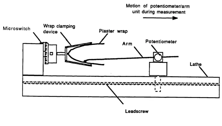
2.2 Layout of the pilot measurement system. 48
2.3 The average rectification map. 51
2.4 The average rectification grid. 53
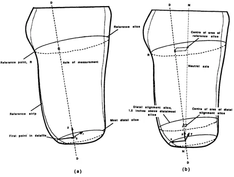
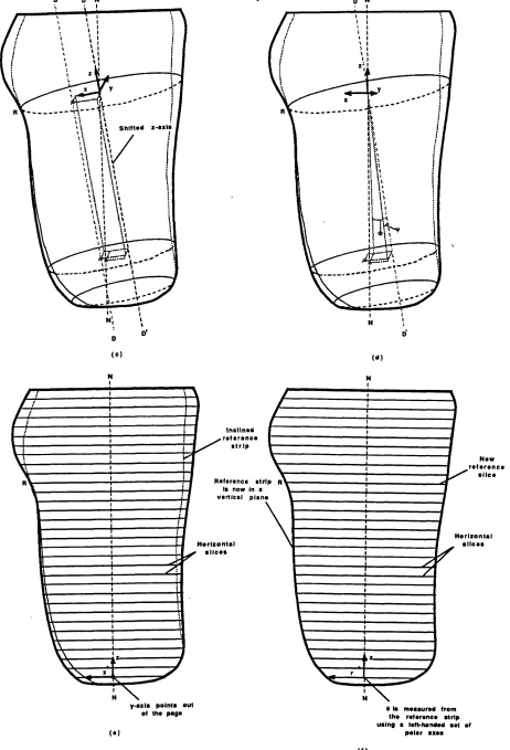
2.5 Axes used during software alignment of prosthetic shapes. 57
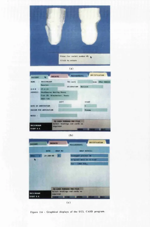
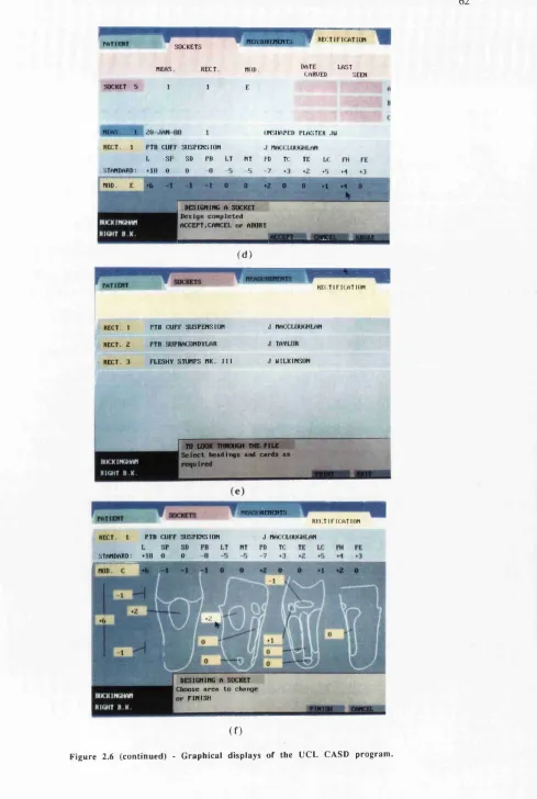
2.6 Graphical displays of the UCL CASD program. 61
Chapter 3 : FE models of indentations
3.1 Compression of a cylindrical specimen. 65
3.2 Error in 'best' iterative FE solutions of uniaxial compression. 70
3.3 Effect of the number of increments used to calculate uniaxial 71
compressive loads using an iterative FE analysis.
3.4 Effect of Poisson ratio upon uniaxial compressive loads. 72
3.5 PAFEC data file for uniaxial compression of a cylinder. 74
3.6 Indentation by a flat-tipped indenter 75
3.7 Distribution of Von Mises stress beneath flat-tipped indenters. 77
List o f figures 10
page
3.9 Nominal stress versus strain for flat-tipped indenters. 78
3.10 Distribution of Von Mises stress beneath round-tipped indenters. 80
3.11 Modelling of round-tipped indenter. 81
3.12 Load versus deflection response for round-tipped indenters. 82
3.13 Nominal stress versus strain for round-tipped indenters. 82
Chapter 4 : Experimental measurements of indentations.
4.1 Effect of interface conditions upon measured compressive loads. 88
4.2 Effect of strain rate upon indenter loads for Q3-3320 elastomer. 89
4.3 Stress relaxation in Q3-3320 elastomer. 90
4.4 Axial versus lateral strain in Q3-3320 elastomer. 91
4.5 Engineering stress versus strain for Q3-3320 elastomer in uniaxial 91
compression.
4.6 Engineering stress versus strain for Q3-3320 elastomer in uniaxial 92
compression and predicted curves from an iterative FE analysis.
4.7 Nominal stress versus strain for flat-tipped indenter, d/h=1.0. 94
4.8 Nominal stress versus strain for flat-tipped indenter, d/h=2.0. 94
4.9 Nominal stress versus strain for flat-tipped indenter, d/h=4.0. 95
4.10 Nominal stress versus strain for Q3-3320 layers of different 95
thickness; flat-tipped indenters, d/h=2.0.
4.11 Nominal stress versus strain for round-tipped indenter, d/h=0.5. 96
4.12 Nominal stress versus strain for round-tipped indenter, d/h=1.0. 97
4.13 Nominal stress versus strain for round-tipped indenter, d/h=2.0. 97
4.14 Nominal stress versus strain for round-tipped indenter, d/h=4.0. 98
4.15 Nominal stress versus strain for Q3-3320 layers of different 98
thickness; round-tipped indenters, d/h=2.0.
Chapter 5 : Evaluation of limb tissue geometry and modulus
on an amputee subject.
5.1 X-ray tracings superimposed upon plots of measured geometry of 105
bone structure and external shape.
5.2 Load versus deflection response of indenter at patellar tendon site. 107
5.3 Effect of muscle contraction upon measured indenter response. 108
List o f figures 11
page
5.5 Results of stress relaxation tests. 112
5.6 Indenter tool. 114
5.7 Calibration jig for the indenter tool. 115
5.8 Indenter load versus deflection at each site. 117
5.9 Nominal stress versus strain for indentations at patellar tendon site. 118
5.10 Nominal stress versus strain for indentations at popliteal site. 119
5.11 Nominal stress versus strain for indentations at anteromedial site. 119
5.12 Nominal stress versus strain for indentations at anterolateral site. 120
Chapter 6 : FE models of idealised residual limbs.
6.1 Idealised limb geometry. 125
6.2 Coarse FE mesh. 126
6.3 Normal pressure profiles for end-bearing models. 128
6.4 Normal pressure profiles for non end-bearing models. 129
6.5 Shear profiles. 130
6.6 Vertical stiffnesses calculated for models 'A' to 'D'. 131
6.7 Vertical stiffnesses of models with various tissue thickness. 132
6.8 'Bony' limb geometry. 132
6.9 ’Average’ limb geometry. 133
6.10 'Fleshy' limb geometry. 133
6.11 Mesh for rectified limb models. 135
6.12 Pressure profiles for rectified models. 136
Chapter 7 : Experimental measurements on a limb model.
7.1 Geometry of physical limb model 141
7.2 Pressure measurement cell. 143
7.3 Cell calibration set-up. 144
7.4 Calibration plot. 144
7.5 Measurement set-up with no distal end-bearing. 145
7.6 Load relaxation during testing. 147
7.7 Pressure versus load for test site 'C'. 147
7.8 Measured versus predicted pressures with distal end-bearing. 148
7.9 Load versus deflection response of limb/socket model with distal end- 149 bearing.
List of figures 12
page
7.11 Load versus deflection response of limb/socket model without distal 150
end-bearing.
Chapter 8 : FE models using measured amputee data
8.1 The limb mesh. 157
8.2 Distal part of the FE mesh. 158
8.3 Assignment of material property numbers to elements. 159
8.4 Inclination of limb axes to the vertical. 161
8.5 Reactions on an element face. 163
8.6 Rectifications applied to give socket shapes. 165
8.7 Effect of rectification upon interface pressure distribution. 166
8.8 Effect of material properties upon interface pressure distribution. 168
8.9 Effect of alignment upon interface pressure distribution. 169
Chapter 9 : Summary
9.1 Flow diagram for an improved CASD system. 175
Appendix A
A. 1 Mapping of an isoparametric element. 186
Appendix B
B. 1 Trial meshes for flat-tipped indenter model with d/h=2.0. 189
B.2 Meshes for flat-tipped indenters 191
Appendix C
List o f figures 13
Appendix D
D. 1 Stress distributions in model 'A'; with end-bearing and a 'totally rough' interface.
D.2 Stress discontinuities across element boundaries along YZ (model 'A').
D.3 Stresses distributions in model 'B'; with end-bearing and a 'frictionless' interface. D.4 Stresses distributions in model 'C'; without end-bearing and a
'totally rough' interface. D.5 Stresses distributions in model 'D'; without end-bearing and a
'frictionless' interface.
page
193
194
195
196
Chapter 1
1 - Introduction 15
1.0 Background
The prosthetic socket is the interface between an amputee and his artificial limb; comfort of this component is a major determinant of his 'quality of life'. The total lower limb amputee population in England in 1984 was 51,130 or just over one person in every thousand. Of these 73% were over 60 years of age [DHSS86a]. The average delivery time for a conventional patellar tendon bearing prosthesis was 69 working days, a significant proportion of the remaining life of many older amputees. An average of 3.2 visits per amputee were made to Artificial Limb and Appliance Centres throughout 1984, 1,907 below-knee prostheses were fitted and the total cost of all artificial limbs supplied was £32 m. A 1983 consumer research survey showed that 33% of amputees interviewed complained of a poorly fitting or uncomfortable prosthesis [DHSS86b].
Socket design is specific to the user and must achieve correct fit while providing stable support of the residual limb through those areas of the skin that can tolerate loading. The shape which is able to do this is not simply a model of the residual limb; distortions are incorporated to the limb contours which judiciously encourage loading in certain areas and relieve in others. This shape manipulation process is termed rectification. In socket production, capture of the limb shape, rectification and socket fabrication are essentially hand skills. Better control at each of these stages and a clearer understanding of how rectification affects socket loading are needed to improve the present 'craft-based' system.
In recent years, the use of computers has benefited the measurement, manipulation
and manufacture of shapes in diverse fields. Research in lower limb prosthetics has used advanced techniques to investigate amputee gait and prosthetic alignment. The prosthetic industry has recently introduced modular artificial limb systems with associated mass production technologies. The first true attempts to introduce computer aided design / computer aided manufacture (CAD/CAM) techniques, however, have focussed on the production of sockets.
1 - Introduction 16
manipulation of shape data rather than rectification on physical models of residual limbs.
The Bioengineering Centre at University College London (UCL) were also committed to the introduction of automated techniques for socket production. Early projects developed RAPIDFORM, a semi-automatic drapeforming machine [DAVIES 85], and later MASTERFORM, a purpose-built carving machine [LAWRENCE85]. These machines were used in a collaborative trial with UBC to replicate the prosthetic shapes designed by their system.
After some experience with the Vancouver software, a pilot study was started at UCL to explore a different CAD philosophy. Initial results were encouraging and development continued with a series of patient trials. During the early months,
software was modified to establish a suite of programs which were thereafter evaluated in a more comprehensive patient study. To date, results show the UCL system to be as successful as traditional methods as far as can be evaluated subjectively. However, whilst improvements have been made by this system in the consistency and speed of production of socket shapes a scientific basis for socket design is still missing and a computer aided engineering (CAE) study has been made in a first step towards a better understanding of the rectification process.
The author’s involvement in the development of the UCL CAD system and this CAE study are the main topics discussed in this thesis.
1.1 Design and manufacture of the patellar-tendon bearing socket.
Design
Socket design aims to transmit supporting loads, enable the amputee to control his prosthesis and provide proprioceptive feedback. The patellar tendon bearing (PTB) socket, designed by Radcliffe and Foort [RADCLIFFE61], is the basis for the design of the majority of below-knee sockets fitted in the United Kingdom.
1 - Introduction 17
experience has shown that the skin covering the tendon is able to tolerate relatively high loads. Flexibility of the underlying tendon provides better 'shock-absorption' during gait than would result at a bony site.
Any tendency of the limb to move back from the patellar bar is counteracted by pressures at the rear. These equilibrating pressures are promoted by another inward bulge, the ’popliteal depression', which gives the posterior tissues an initial compressive strain prior to loading. Pressure is similarly encouraged in the ’fleshy’ areas to the medial and lateral sides of the tibia, mainly to provide mediolateral stability.
The areas described have, in general, a relatively thick layer of soft tissues covering the bone structure and small movements of the socket wall with respect to the liriib during gait therefore are less likely to produce high strains and stresses. Another site where significant load is borne is at the medial tibial condyle. Although this is covered by a thin layer of soft tissue, the flaring of the tibia presents a large area at the right inclination to support vertical loads.
The locations of these pressure tolerant areas are shown by 2 views of a right limb in figure 1.1 (a).
PRESSURE-TOLERANT AREAS
POSTERIOR (
\ ANTERIOR
SEN SITIV E AREAS
POSTERIOR /
ANTERIOR
(b)
Figure 1.1 - Pressure tolerant/sensitive areas of the residual limb, (after Radcliffe & Foort, 1961)
1 - Introduction 18
covers a bone and high stresses arise more easily. This is especially true where there are prominences such as at the head and cut end of the fibula, the sharp crest of the tibia and the anterolateral and anteromedial aspects of the tibial condyles. These are shown in the anterior view of figure 1.1 (b). At the rear, the tissues covering the hamstring tendons are prone to pinching between the posterior brim of the socket, which is trimmed away here to permit knee flexion, and the tendons themselves, which become tensed during this flexion.
The distal end of the residual limb presents a large area which might be thought suitable to support vertical forces but frequently scar tissue prevents this. Another factor which may make it unsuitable for high loading is the concentration of stress caused by the underlying cut bones. For the majority of residual limbs distal end
bearing is prevented.
Although the areas shown in figure 1.1 (b) are usually termed 'pressure sensitive' in prosthetics, the loads which may damage the skin and underlying tissues may be in the form of direct normal pressure, shear forces acting tangentially to the surface of the limb or a combination of these. A high magnitude, coupled with prolonged duration, of normal pressure on body tissues has been shown to restrict blood flow and retard local metabolism [KOSIAK58]. Shearing forces have also been found destructive [ROAF76]. A combination of pressure and shear has been shown to be especially harmful [BENNETT79]. There is evidence too that cyclic pressures of low magnitude can be harmful [BRAND75].
In the original PTB design, a rigid shell made of glass reinforced plastic was used which incorporated the contours described. The rigid shell was lined with a closed cell polymer foam material, Kemblo, which deforms locally to redistribute loads and 'even out' peaks. Radcliffe and Foort also recommended total contact between the residual limb and the socket liner. This gives the greatest available area over which to distribute load and yields a pumping action during gait that helps return venous blood and prevent oedema. An additional benefit is that sensory feedback is likely to be improved if the limb can perceive pressures all over its surface.
1 - Introduction 19
unrestricted flexion/extension but must avoid excessive slack which may cause an undesirable piston action. Cuff suspension is still the most commonly used suspension system in England and Wales.
Variants of the original design
The main deviation from the original PTB design has been in the method of suspension. An important area to react mediolateral moments is absent with the cuff suspension system. These moments can cause instability of the knee and, for short limbs especially, support here is important In the alternative supracondylar system, the socket walls are high on the medial and lateral sides and wrap closely over the femoral condyles to provide suspension and mediolateral knee support. With pliable plastic sockets, the flexibility of the socket material is sufficient to permit the side extensions to expand and thus allow the knee joint into the socket. Sockets made of stiffer materials require wedge inserts on the medial side to 'lock' the condyles in. The majority of sockets fitted in Scotland and the USA use the supracondylar suspension system. The KBM socket is a German variant of this.
The supracondylar/suprapatellar suspension system has, in addition to high mediolateral walls, a high anterior wall which fits closely over the patella. This provides anteroposterior stabilisation of the knee, especially at toe-off, which reduces the tendency for the knee to hyperextend. The anterior wall may also provide an additional load bearing area. A drawback, however, is that the brim is often cumbersome, for example, when kneeling.
Other variations on the original design relate to liners and limb 'socks'. A number of different closed cell foams are currently used as liner materials. Unfortunately all of these undergo permanent deformation with age which restricts their useful life. Pelite is
the most commonly used material in the UK. Wool, nylon or cotton 'socks' also improve socket comfort. Woolen socks are able to redistribute loads like foam liners, but are too frequently used to make up for an oversized socket. The main function of nylon socks is to reduce friction during gait by providing an interface between the residual limb and socket that is relatively free to slide. Cotton socks, to a limited extent, combine these functions and are better absorbers of perspiration. If regularly changed, limb socks can improve the 'microclimate' of the socket, reducing the bacteria which accelerate tissue damage.
1 - Introduction 20
shell in contact with the residual limb or limb sock. Direct loading of the limb by the frame occurs only in the rectified supporting areas, leaving the flexible shell relatively free to distort elsewhere during gait. Although their use has been more widely exploited for above-knee prostheses, improvements have been noted in the brims of below-knee versions [SCHUCK86] and in the ability to assess these clear sockets [FISHMAN87].
Manufacture
The manufacture of below-knee sockets may be separated into four stages. These are casting of the residual limb, manufacture of a plaster positive from this cast, rectification of this positive and, finally, manufacture of the socket using the positive cast as a former. An outline follows of the method currently used by prosthetists at Roehampton.
Prior to casting, the residual limb is covered with a thin nylon sock upon which locations of anatomical features are 'mapped' in indelible pencil. The patella, patellar tendon, fibula head, tibia and hamstrings are typical features identified. When this mapping is complete, plaster of paris bandages are wrapped over the limb and sock. Approximately 15° of flexion at the knee is used during casting to emphasise the anatomical features.
As the plaster starts to set, the prosthetist encourages the limb cast into a shape more suitable for load bearing (figure 1.2). The thumbs are used to indent by the patellar
tai
patellar t e n d o n ''
1 - Introduction 21
tendon while, at the rear, the other fingers press into the popliteal tissues, which mainly consist of the gastrocnemius. The prosthetist uses his subjective judgement and adjusts the contouring of the plaster wrap according to the 'stiffness' properties of the tissues sensed manually. Thus a degree of rectification is introduced at the casting stage. The cast is removed when fully set.
A positive model is then prepared by pouring plaster mix into the wrap cast. The map marked by the prosthetist becomes imprinted on this model. It is usually at this stage that an axis is established within the prosthetic shape. Before filling with the plaster mix, a mandrel is positioned within the wrap cast. The orientation of the prosthetic shape relative to this mandrel is maintained throughout rectification and socket fabrication and eventually fixes the 'bench' alignment which determines the initial set-up of the socket on the artificial limb. Radcliffe and Foort recommended tilts to the vertical, in both the sagittal and frontal planes, which tend to cause flexion and adduction at the knee in flat footed stance. How these tilts are interpreted seems widely open to individual preferences.
When the wrap cast has been cut away from the plaster positive it is ready for rectification. This is a sculpting process in which material is removed in those areas where pressure is to be applied and added where high pressure is undesirable. Rasps and files are used to create the depressions and new plaster is built on in smooth patches which raise the surface.
Final manufacture of the hard shell socket is commonly achieved in England and Wales by drapeforming by hand or with a semi-automatic RAPIDFORM machine. The Pelite liner, typically 7 millimetres thick, covers the positive model before a pre-heated polypropylene sheet or preform is drawn down to form the socket shell. Vacuum is applied to encourage conformity between all surfaces. Once the polypropylene has cooled, the plaster positive is broken out and residual material is trimmed away to complete socket fabrication. Glass reinforced plastic lay-up is an alternative method of socket manufacture that is often used in Scotland and the USA.
Assessment
1 - Introduction 22
fit is not completely satisfactory, small changes can be made by removing material from the liner or occasionally by glueing in an additional patch. If the socket fit is very poor, the entire manufacture process must be repeated.
The alignment - the position and orientation of the prosthetic components relative to one another - affects both the kinematics and kinetics of amputee gait and significantly influences socket comfort. Subjective evaluation of gait is used and limb components are adjusted to compensate for any gait deviations.
The kinematic problem is to give normal appearance throughout the gait cycle. This criterion is not satisfied for some amputees who can often be seen to scuff their feet on swing through, sway their upper body or have an excessively wide walking base. In
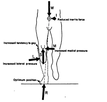
satisfying kinetic criteria attempts are made to minimise the moments produced by the coupled actions of the ground reaction forces and those applied by the residual limb. This must be done for any stage of the gait cycle and while standing. Figure 1.3 shows the effect of an inset of the foot at an instant during the gait cycle. Here the socket loads have been resolved into vertical, medial and lateral components.
R educed insrtio (ore*
Increased tendency to gap
Increased medial pressure
Increased lateral pressure
Optimum position'
Figure 1 3 • The effect of a foot inset upon socket loading. (after Radcliffe & Foort, 1961)
1 - Introduction 23
have described parameters by which alignment may be defined and have identified ranges of these parameters which provide acceptable alignment [ZAHEDI86]. Other investigators have studies the effect of alignment changes upon measured kinematic [HANNAH84] and kinetic [WILSON79] data. An objective means of providing satisfactory alignment in the fitting room has yet to be found.
Medical factors
The majority of residual limbs can be accommodated using the standard procedures described above since most have broadly similar shape and function. This can be explained in terms of similarities in the causation and surgical techniques used for amputation. The vast majority of amputations are due to peripheral vascular disease (63.7% in the UK in 1986) [DHSS86a] or diabetes (20.2%) and a long posterior skin flap is widely used in surgery for these and other cases.
The lower limb amputee population in England is presently divided roughly equally between below- and above-knee cases. As medical and surgical techniques improve an increase in the proportion of below-knee amputations, preserving the natural knee function, is expected. This appears to have been the trend in the USA - since 1965 the ratio of above to below-knee amputations has been reversed from 70:30 to 30:70 [KAY75].
For several days after amputation, residual limbs usually contain significant oedema. As healing progresses, oedema generally diminishes and the limb volume is reduced. Many surgeons recommend that amputees be up out of bed and walking on a temporary prosthesis at the soonest possible date. By traditional methods, however, early supply of a temporary prosthesis is difficult and this may need replacing frequently as the volume reduces to a stable state.
In summary, below-knee socket design is founded upon a basic application of biomechanical concepts and the craft-based manufacturing processes are slow and too often unsuccessful. Conventional production methods allow no objective feedback since shape information is lost when wraps and rectified positives are destroyed and there is therefore no logical path which may be followed to improve fit consistently. Since a number of different technicians may be engaged in producing any prosthesis
and there are few quantitative standards to work to, communication of an amputee's needs can easily be misconstrued. On an international, and even national level, there is much 'flexing' of the basic guidelines by which prostheses are produced. The lack of
1 - Introduction 24
requires much hands-on experience. There is a worldwide shortage of trained prosthetists.
1.2 Potential advantages of CAD/CAM in prosthetics.
Computers are being used increasingly to aid the design and manufacture of durable goods. A product typically may evolve firstly with an idea which is rapidly modelled and viewed graphically. The aesthetics of this design may be assessed and an analysis may be performed to test its functionality before a physical prototype is produced. In the case of a mechanical component, the latter stage of assessment may be a stress analysis of the component in use.
In manufacture, numerically controlled machines under the supervision of a computer may produce those components of the product with complex geometry. Industrial robots may perform simpler, repetitive process with great precision. The above description may invoke an image of the automotive industry but the processes may equally apply to the production of modular prostheses in appropriate economic circumstances. Advantages of this type of CAD/CAM implementation are mainly in the speed of design and manufacture and in the control of quality and cost
Some prosthetics components, essentially the socket and cosmesis, require custom design. The implementation of CAD/CAM technologies for these articles will differ from the above description and this is described fully in subsequent sections of the thesis. A number of potential advantages of numerically based design and manufacture techniques, however, may be identified immediately.
1 - Introduction 25
shape. Improvements made in socket productivity and prosthetic training may in turn provide economic benefits.
1.3 Introduction of CAD/CAM systems into prosthetics.
Prior to the development of the UCL computer aided socket design (CASD) system only Saunders and Foort of UBC, Vancouver had produced a computer based system
for designing lower-limb sockets. The UBC software uses a limited number of limb measurements to scale a 'reference' PTB socket shape to provide a reasonable socket design. Thereafter, interactive modifications are made to the shape on-screen to produce the final fit. Sets of measurements are taken with calipers and tape-measure. More sophisticated devices appropriate for limb measurement were unavailable at the time of development.
Anteroposterior and mediolateral measurements at the knee are used by the software to scale the proximal part of the reference socket in cross-section and length before anteroposterior and circumferential measurements distal of the knee joint, at one inch intervals, are used to 'taper' the scaled reference shape. The tapering measurements are taken with tissues under compression from a suspension casting system. Final modifications, where patches of material are added or removed to improve fit, are made via an interactive graphics display which can produce wire frame models and plots of cross-sections.
In numerical terms, the 'scaling' and 'tapering' operations are transformations of the reference shape which is stored as a set of cylindrical polar coordinates. The patches are added to the transformed shape by superimposing displacements onto the coordinate data. These are generated using bi-beta functions which have zero magnitude and gradient at their boundaries. This system has been commercially available since 1986.
1 - Introduction 26
explored, based upon statistical analyses of the differences between limb shapes and conventionally designed socket shapes. Parameters which were to be examined were ratios of the radii, circumference and cross-section of the rectified and unrectified shapes. To permit these comparisons, an axis was to be set on each shape with respect to four anatomical landmarks - three around the knee and one at the distal end. In the final system, it was envisaged that the design algorithms would be able to transform the mathematical surface representing the residual limb into a socket shape. No further publications have been found which indicate whether this prototype ever became a
reality.
Algorithms used by both of these systems deal only with shape information and, by assuming that some degree of standardisation is possible, transform one set of shape data into another. Regardless of how 'intelligent' these transformation processes are made, if they are based upon external shape data alone they will yield a unique socket for a given limb shape. Comfort, which depends primarily upon the loads at the interface between the residual limb and socket, cannot be guaranteed because the underlying structure of limb will affect these loads. A better understanding is needed of how damaging interface loads arise before significant improvements in CAD systems can be assured.
1.4 Evaluation of interface loads.
Interface loads may be measured or they may be predicted using analytical models. A review follows of research in these and related areas.
1.4.1 Measurements
A number of investigators have measured normal interface pressures on below-knee sockets whereas no measurements of shear loads have been found in the literature.
1 - Introduction 27
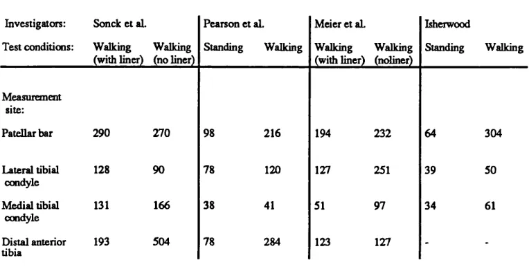
walking in groups of subjects wearing lined or unlined sockets [MEIER73]. Capacitance type transducers 20 mm in diameter were used which were stated to have a 'bench test' accuracy of ±20%. Isherwood used welded PVC bags filled with water, which were connected to a silicon diaphragm transducer, to measure pressures in a lined socket at 6 sites [ISHERWOOD78]. The subject's bodyweight was 753 N. The measurements areas of Isherwood's devices were large - between 17 and 58 cm2. The main results from these investigations are tabulated in figure 1.4.
Investigators: Sonck et al. Pearson et aL Meier et aL Isherwood
Test conditions: Walking (with liner)
Walking (no liner)
Standing Walking Walking
(with liner) Walking (noliner) Standing Walking Measurement site:
Patellar bar 290 270 98 216 194 232 64 304
Lateral tibial condyle
128 90 78 120 127 251 39 50
Medial tibial condyle
131 166 38 41 51 97 34 61
Distal anterior tibia
193 504 78 284 123 127 -
-Figure 1.4 Table of published interface pressure measurements in below-knee sockets.
(Values are in kPa)
In a research environment, the use of pressure transducers is a cheap and relatively simple way of evaluating normal interface loading. These devices are being made smaller, thus reducing errors due to averaging effects over the measurement area as well as those introduced by curvatures of the loaded surface.
The main practical disadvantages of taking pressure measurements in the clinic are twofold. Firstly, each subject requires an experimental socket in which transducers must be carefully mounted and this will, most probably, not become a service socket. Secondly, assuming that pressure peaks may occur anywhere at the interface, they are not easily located by transducers which can only measure pressures at discrete locations.
1 - Introduction 28
measure socket interface loads, however, since pressure and shear, or combinations thereof, are registered. Their use in prosthetics is infrequent; probably because similar qualitative information of direct relevance to tissue damage is freely available to the prosthetist by observing skin discolourations on the limb.
In addition to the practical complications of locating and measuring peak pressures in the clinic, the usefulness of such data to a CAD/CAM system is questionable. It is reasonable to state that a socket found to be causing an unacceptably high pressure at a particular location must be redesigned and that relief in the 'problem area' will reduce this pressure, but the amount of relief needed and its precise shape and location remain unknown. An iterative trial-and-error method of design, pressure measurement and redesign is impractical. Far preferable is to be able to predict the distribution of interface loads in advance of fabrication and this is only possible with an understanding of the mechanics of loading of the residual limb by the socket.
1.4.2 Pre-requisites for modelling socket loads.
An analytical model of a residual limb supported by a socket, which is capable of predicting interface loads, will require information regarding the geometry and mechanical properties of the socket and the residual limb tissues.
The socket
In Chapter 2 it will become evident how measurements of socket shape are obtained. Below-knee sockets made at the Bioengineering Centre are made of polypropylene (Young's modulus approximately 1.2 GPa) and have wall thicknesses between 3 and 7 mm. These sockets are designed to be rigid. Pelite is used exclusively for the manufacture of socket liners in the Bioengineering Centre. An approximate modulus, obtained from tests which compressed discs of this material, is 350 kPa.
The limb tissues
1 - Introduction 29
T l t l A U S A H T I A iO R
PLEXOR oiaiTonuM
L0 N 4 U 3
P O S T IfllO A T lB lA c N ER a n d v e s i t »
P I ^ N T A P J s V "
A++0 V I I J I U
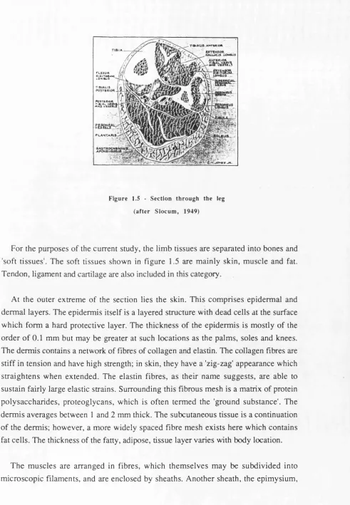
Figure 1.5 - S ection th rough the leg
(afte r S lo c u m , 1949)
For the purposes o f the current study, the lim b tissues are separated into bones and 'soft tissues'. The soft tissues shown in figure 1.5 are m ainly skin, m uscle and fat. Tendon, ligament and cartilage are also included in this category.
At the outer extrem e o f the section lies the skin. This com prises epiderm al and derm al layers. The epiderm is itself is a layered structure with dead cells at the surface w hich form a hard protective layer. The thickness o f the epiderm is is m ostly o f the o rd er o f 0.1 m m but may be greater at such locations as the palm s, soles and knees. The derm is contains a network o f fibres of collagen and elastin. The collagen fibres are stiff in tension and have high strength; in skin, they have a 'zig-zag' appearance which straig hten s when extended. The elastin fibres, as their nam e suggests, are able to sustain fairly large elastic strains. Surrounding this fibrous mesh is a matrix of protein p o ly saccharides, proteoglycans, w hich is often term ed the 'ground substance'. The derm is averages between 1 and 2 mm thick. The subcutaneous tissue is a continuation o f the derm is; how ever, a m ore widely spaced fibre m esh exists here which contains fat cells. The thickness o f the fatty, adipose, tissue layer varies with body location.
1 - Introduction 30
encloses the whole muscle. Blood vessels and nerves are distributed through the muscles.
Tendon, ligament and cartilage exist at joints and do not appear in figure 1.5. Tendons connect muscle to bone and are soft connective tissues which contain densely packed collagen fibres. They are therefore stiff and strong. Ligaments connect bone to bone and are more compliant since fibres are less regularly arranged. Cartilage at the knee joint, for example, is largely made up of proteoglycans and water which are covered with a mesh of collagen fibres. This is suitable for withstanding high loads.
The bones are the prime tissues through which forces are transmitted in the body and thus they have evolved as stiff structures. Published values of compressive and tensile moduli for the tibia fall in the range 1.2 to 1.4 GPa [YAMADA70, EVANS73]. The compact bones such as the tibia and fibula are made up of many units which surround vascular channels. These units are themselves made up of sheets of bone tissue. The outer surface of all bones is covered by a layer of fibrous tissue, the periosteum.
The larger blood vessels and nerves pass between the tissues described.
Measurement of limb tissue geometry may be accomplished in a number of ways. The external limb shape may be sensed using various tactile or optical devices and radiographic, or other, scanning techniques may provide images which show the geometry of underlying tissues. This subject is discussed further in Chapter 5.
A means to measure and characterise the mechanical behaviour of the limb tissues is less readily identified. The literature shows that the most popular noninvasive approach for measuring the compressive properties of soft tissues has been to use an indenting tool to measure a load versus deflection response. Few authors have been able to use these data other than for qualitative comparisons. Of interest in these publications are observations about the measured responses, their time-dependence and the practicalities of their measurement.
1 - Introduction 31
and 'instantaneous' and 'creep' components of deflection were identified. Differences were observed between groups of old and young subjects; the younger group demonstrated larger deflections of both type. Tests were repeated three times in succession at the same location and the magnitudes of both components of deflection were found to be greater in the first than in subsequent tests. Another study
demonstrated a greater compliance of skinfolds in females than in males [CLEGG66].
A study by Hickman et al. measured the response of skin and subcutaneous tissues at the ear lobe and anteromedial aspect of the tibia [HICKMAN66]. Loads were applied by round discs of various diameters and deflections of these were measured. One series of tests measured deflections 15s after a step pressure, in a range between 0.7 and 27 kPa, had been applied. Tests on the ear lobe of an asymptomatic subject showed that relatively low pressures produced engineering strains in excess of 25%. Above this strain the tissues exhibited a much stiffer response. A series of ramp tests demonstrated the existence of hysteresis in the ear lobe tissues.
Creep tests were also performed which involved the application of a step pressure followed by a period of constant pressure loading. Strains occurred rapidly over the first few minutes of loading and continued, although at a much reduced rate, for a test period of 3 hours. Similarly, when load was removed a large proportion of the strain was recovered rapidly but strain remaining after this was recovered more slowly. In oedematous tissue, a loss of initial elasticity and slower rates of creep and recovery were observed; however, the opposite effects were found in obesity.
Other tests counted the flow rate of radiosodium injected into the blood to show the effects of loading upon blood flow. A nominal pressure well above the capillary pressure of 3.3 kPa was found necessary to seriously impair blood flow in the forearms of asymptomatic subjects. Circulatory recovery was found to precede the delayed viscoelastic recovery from the effects of applied pressure.
Another apparatus was produced which used a force transducer and a LVDT to measure loads and deflections of both spherical and flat indenters [ZIEGERT78]. Responses were recorded at three sites on the anteromedial aspect of the tibia of a number of asymptomatic subjects. A nonlinear load versus deflection response was obtained; although, this became linear above loads of about 13 N. The indenter
1 - Introduction 32
again occurred; however, this did not increase significantly with time. Further tests preconditioned tissues by applying a constant indenter load for 5 minutes and found that the load versus deflection response of these tissues was near-linear. The gradient
of the response was assumed to be a representative tissue stiffness. Measured stiffnesses varied by up to 70% between sites on any given subject and by up to 300% between subjects at equivalent sites. Results from tests taken at the same site at least 24 hours apart were repeatable within 20%.
Indentation tests on skin and subcutaneous tissues have shown behaviour to resemble that of viscoelastic solids. The mechanism of the time-dependent deformation is not fully understood; some authors have postulated theories to explain it.
Hickman et al. proposed that deformation caused by applied normal pressures contains an elastic and a viscoelastic component [HICKMAN66]. The former was comprised of elastic strains within the fibrous matrix and compressive and shear strains in the ground substance. These deformations were thought to distort the capillaries and larger vessels, thus reducing blood flow. Since a large proportion of the applied load is carried by the fibrous matrix and ground substance, however, the full magnitude of the applied pressure is not transmitted to the blood. The viscoelastic component of the deformation was felt to be due to flow of the ground substance under the action of stress gradients. This gradually causes further distortion of the vessels and hence a further reduction in blood flow. The rapid recovery of blood flow upon unloading was attributed to the recovery of the larger elastic component of deformation.
Ziegert and Lewis emphasised the importance of extracellular fluid and assumed the skin and subcutaneous tissues at the anterior aspect of the tibia to resemble an elastic membrane covering a porous elastic material filled with a viscous fluid [ZIEGERT78]. It was felt that the elastic membrane does not act as a major load-carrying member.
They attributed an initial creep response to the outflow of this fluid under low loads whereas, with all the fluid displaced, the porous structure acts in a nearly linear-elastic
fashion. Guyton states that a small portion of interstitial fluids are free to flow but that the major portion is held tightly by hydrated substances [GUYTON71].
1 - Introduction 33
the interstitial fluids. Lanir [LANIR88] has attributed this increased resistance partly to osmotic pressures.
Measurements of the load versus deflection response of indentations offer no direct indication of stress-strain relationship for the indented material. Some authors, however, have analysed stress and strains beneath indenters theoretically.
An analysis of the stresses within an elastic material was performed which combined classical linear-elastic theory and a variational approach [BENNETT71]. Homogeneous, isotropic behaviour was assumed for a continuous layer of material resting on a rigid base. A solution in two dimensions only was considered in which an indenting beam was assumed to extend infinitely normal to the plane of interest. Compressive and shear [BENNETT72] stresses were analysed beneath beams of various geometry. The predicted compressive stresses beneath the beam varied only with depth into the layer, not with the distance across the beam. These stresses fell rapidly with distance from the edge of the beam. The maximum predicted shear stresses were located at or beyond the edge and as the ratio of the beam width to layer thickness was reduced shear stress was found to increase. The general distributions of compressive and shear stresses predicted by the theory were confirmed experimentally by measuring deformations of a grid marked on a section of silicone gel. The measured strains were used to calculate the stress distribution once the material properties of the gel had been established [BENNETT73].
The equilibrium of an infinite elastic layer indented by a rigid axisymmetric indenter has also been considered [HAYES72]. The elastic layer was assumed isotropic, homogeneous and rigidly restrained on its underside and deformation was assumed
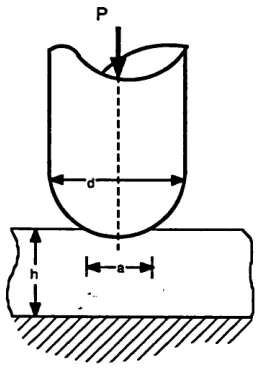
frictionless. Indentations using hemispherically-tipped indenters (figure 1.6) were considered and these were represented mathematically by a mixed boundary value problem which satisfied the equations of linear-elastic theory. The aspect ratio, d/jj of
the material beneath the indenter was identified as an independent variable which
described indentations. Increasing was found to decrease the indentation for a
given applied load. This is expected since a larger radius of curvature of indenter tip will produce a larger contact area, Ila^ (figure 1.6). Maximum compressive stresses
1 - Introduction 34
P
Figure 1.6 - Indentation of an elastic layer by a round-tipped indenter.
Finite element (FE) models have been created of similar indentations by round-ended indenters of various curvature [BRUNSKI80]. Models were produced of indentations into a layer of skin 2 mm thick, having a Young's modulus of 2.76 MPa, which covered an 18 mm thick layer of fat and muscle with a modulus of 0.162 MPa. Both materials were assigned a Poisson ratio of 0.49. Indentations were made up to 10% of the total thickness of the tissue layers. Vertical stresses calculated at the surface were concentrated on the axis when the indenter tip was hemispherical. Where the tip radius of curvature was larger, and the end was therefore flatter, peak stresses were nearer the circumference of the contact region. Maximum Von Mises stresses were found to be higher with the more pointed indenter and high stress regions were located near the contact radius in the skin and on the axis just below the skin. With the flatter indenter, high Von Mises stresses were located near the rigid base in the softer layer.
In a thesis, Schock presents results of indenter tests on an excised section of skin, subcutaneous fatty tissue and muscle of a Yorkshire pig [SCHOCK81]. Pig skin has been used in a number of biological studies due to the similarities between its structure and that of human skin [WINTER76]. Values of compressive modulus were obtained using measurements of engineering strains beneath the indenter of up to 50% and stresses predicted by a finite difference (FD) model. Lower moduli had previously
been obtained from uniaxial compression tests on in vitro specimens of the tissues. In
1 - Introduction 35
other publications on in vitro uniaxial compression tests have been found. Results of
Schock's tests are summarised in figure 1.7.
Indentation test Compression test Tissue:
Skin 420 80
Adipose tissue 150 50
M uscle 340 120
Figure 1.7 - Estimated compressive modulus of excised pig tissues, (after Schock, 1981. Values are in kPa)
The stress contours produced by the FD model were generally similar to those predicted by Brunski's FE model with round-ended indenters. A model of a flat-ended indenter identified highly concentrated compressive and shear stresses around the edge.
In a second series of indentation tests, a grid was marked on the in vitro specimens.
Measurements of grid displacements were used to calculate the distribution of compressive strain beneath indenters. Differences between distributions from flat and round-ended indenters were similar to those shown in the compressive stress distributions predicted by the FD models.
The literature reviewed has shown mostly observations of stress distributions and only Schock has offered a stress-strain relationship for soft animal tissues in compression. A great deal of research has been performed to find stress-strain relationships for various soft tissues in tension and, to a lesser extent, torsion. These
studies have mostly taken measurements from in vitro specimens of separate tissues
which have been assumed homogeneous. Skin has received most attention. The methods of analysis and assumptions used are of more interest to the current project than the actual expressions derived to describe behaviour.
1 - Introduction 36
Finite strain theory is appropriate for the analysis of large deformations and has been used by some investigators. In general terms, these studies assume tissue behaviour to approximate that of a continuum and aim to find expressions for the strain energy per unit volume in specimens as a function of the priniciple extension ratios. A full development of the theory used appears in [GREEN60] and more concisely in [SAUNDERS64]. An exponential form of strain energy function has been used to describe large uniaxial extensions of cat skin [VERONDA70]. Both compressible and incompressible behaviour were assumed and results using the former assumption were superior. Other exponential forms have been produced for soft tissues in uniaxial tension assuming isotropic, incompressible [GOU70, DEMIRAY72] and orthotropic [TONG76] behaviour. Muscle fibre in torsion has also been studied assuming isotropic, incompressible behaviour [SNYDER72].
Some studies have assumed the structure of individual fibres to have a particular configuration and mechanical analysis of the simple structure proposed has yielded an expression of the load-extension relationship for each fibre. This expression is then extended to give a stress-strain equation for a fibrous network. Parameters, which are dependent upon the material properties and geometry of each fibre, are evaluated by fitting the derived equation to experimental data. This technique has been used for skin with a model based upon the stretching of collagen fibres [RIDGE64] and, more recently, for a number of different collagenous tissues [DECRAEMER80a, MAN S CHOT86].
Attempts to define the behaviour of soft tissues more fully have incorporated time as an independent variable. The viscoelastic behaviour of human skin is demonstrated by the existence of hysteresis, stress relaxation and creep phenomena [BARBENEL78]. Studies have mainly used stress relaxation and oscillating strain tests in one or two
dimensions and have attempted to produce a phenomenological mathematical description of viscoelastic behaviour. The general theory used is described in [LOCKETT72]. Logarithmic relationships between applied stress and time have been formulated to describe stress relaxation tests on skin [BARBENEL73] and mesentery [FUNG72]. Parameters within these relationship, however, vary with the level of
applied strain. Linear functionals which relate stress to strain history have been
1 - Introduction 37
In vivo assessment of the compressibility of separate tissues is difficult since
deformations in three dimensions must be measured. Measurements made in vivo
should not overlook the fact that specimens generally are not isolated structures and that there may be an exchange of blood or interstitial fluids with the surrounding
tissues. In vitro testing is also difficult since fluid loss is likely. Many analyses of
separate tissues have assumed incompressible behaviour and it would appear that body tissues are practically incompressible. Hydrostatic pressures cause little or no deformation; the human body is capable of tolerating a pressure of 1655 kPa deep under water [CHOW78]. Deviatoric stresses are found to have far more effect; a uniaxial pressure of less than 6.7 kPa has been found to induce pathological changes [HUSAIN53].
It is generally accepted that skin is anisotropic [KENEDI65]. Observation of the fibres within the tissue structure have helped explain this directional dependence [FINLAY69]. Muscle fibres and collagen fibres within tendon are aligned specifically to give tissues with strength in a preferred direction. Nevertheless, isotropic behaviour is often used as a first approximation to analyse stresses and strains in soft tissues.
An interesting practical point raised in the literature is that in the first few cycles of
loading of a fresh in vitro specimen of skin, the hysteresis effect progressively reduces
to a stable state; a phenomenon termed preconditioning. Usually, only preconditioned specimens are considered mechanically stable for testing. Preconditioning has been
explained as an irreversible reorientation of fibres which, in vivo, will not be removed
until the subject is free to move and apply normal physiological stresses and strains [STARK71].
Finite strain and viscoelastic analyses have been used to produce relationships which describe the behaviour of a number of soft tissues under well-controlled conditions of tension and torsion. No general relationships exist to describe a triaxial stress state. Were such relationship to exist, assumptions regarding the mechanical interaction
1 - Introduction 38
1.4.3 Existing models of tissue deformations.
As well as the indenter model mentioned, a few other problems relating to body support have been tackled using the FE method.
A FE program was written to model a buttock of a sitting person [CHOW78]. Solutions were obtained using a 33 element axisymmetric mesh, applying loads incrementally to produce a nonlinear solution. A value of 15 kPa was used for the Young's modulus of a homogeneous buttock tissue layer which covered a rigid bone. The Poisson ratio was 0.49. The importance of Von Mises stresses was emphasised since these indicate the degree of deformation in an incompressible material. A number of loading mechanisms were proposed and it was found that peak Von Mises stresses were smallest when the applied pressure distribution was most uniform and applied shear forces were minimised. A model of the buttock supported by a flat, frictionless interface calculated maximum Von Mises stresses to be on the axis next to the rigid bone and the authors commented that this corresponds with clinical findings since pressure sores frequently are initiated beneath the skin. The load versus deflection response of the bone in this model was compared with a response measured on a physical model which used a wooden bone and a tissue layer made of a gel. Rough agreement was obtained for small deflections; however, a greater stiffening in the physical model caused the two plots to diverge.
The plantar tissues of the foot have been modelled using a FE analysis [NAKAMURA81] and a FE model has aided the design of skin flaps in surgery [LARRABEE86]. Other analyses of stiffer biomechanical structures, mainly bones and prosthetic implants, have applied FE theory. A review of some of these appears in [HUISKES82].
The only FD study of tissue deformations found in the literature is the axisymmetric indenter model of Schock.
1.4.4 Strategy for a limb model.
1 - Introduction 39
may vary as increasing loads are applied. Deformations are time-dependent. In compression, time-dependence may be due to a proportion of intercellular fluids which are free to disperse.
A great deal of research will be needed to obtain precise results from a mathematical model of a loaded limb. In the current project, assumptions are made about tissue behaviour so that a 'first generation' model may be produced. In formulating this model, the main objective is to build a qualitative impression of the parameters which have the greatest influence upon interface loads. Areas can thereby be identified for future investigation so that improved results may be obtained. Another objective is to furnish a means by which mechanical measurements of limb tissues may be taken in a normalised form. In the near future these measurements may be used by an improved CASD system to base socket designs upon a fuller description of the residual limb.
Due to the complex geometry and mechanical properties presented, techniques which may be used to model interface loads are scarce. The FE and FD methods, however, appear to be possible candidates. These are numerical techniques by which solutions to complex differential equations may be obtained using computers. Each has its pros and cons.
The FE method is capable of defining complex geometry in the form of a mesh of elements. Complex boundary conditions also may be modelled. A large number of commercially available FE packages exist which have the flexibility to define and analyse a wide range of problems. The main drawback is that the technique is best suited to linear analyses. In the FD method, a grid is used to represent the domain of the problem. Boundary conditions may be defined which apply all along the boundary rather than at discrete nodes and solutions to nonlinear problems may be more accurate than by FE methods. Time-dependent problems are well suited to solution using FD analysis; however, solutions to equilibrium problems are generally computationally less efficient than by the FE method. Another drawback is that definition of boundary conditions, especially for boundaries with irregular geometry, is complex. No general purpose FD packages exist.
1 - Introduction 40
are known for soft limb tissues, assumptions about stress-strain relationships must be made. In a first generation model which assumes a linear constitutive law, a major
benefit of FD analysis, therefore, will not be gained.
Precise values of predicted interface loads appear to be unlikely in a first generation model; however, it is hoped that FE models using idealised material behaviour but realistic geometry and boundary conditions will provide a foundation upon which
improved models may be built The assumptions that are made to idealise the material behaviour are that the soft tissues are locally homogeneous, i.e. that inhomogeneous effects ’even-out1 at a given section through the soft tissue layer. Similarly, anisotropic
effects shall be assumed negligible. It will also be assumed that the mechanism of tissue deformation is unchanged at all strains and a linear constitutive law is obeyed. By collecting mechanical data using controlled strain rate and by modelling static loads only, time-dependence shall be assumed to have uniform effect all over the limb. The assumption of linear and purely elastic behaviour of soft tissues may at first appear gross; however, it has been proposed that the nonlinearity and time-dependence under the action of uniaxial stresses is due mainly to a limited dispersion of fluids. In a total contact socket, it is an objective to apply pressure all over the limb surface and avoid the large gradients of pressure which may cause significant fluid dispersion.
1.5 C o n cu rren t developments
A number of relevant studies have been reported since starting the current project. In the area of shape design, above-knee socket and shoe insole shapes have been produced using a commercial CAD system [VANDERLIN86]. The UBC software development has continued and currently 9 reference shapes are available. This has extended the family of shapes that may be generated [SAUNDERS88].
1 - Introduction 41
takes 6 minutes. The idealised bone structure was located within the soft tissues using ultrasonic measurements and formed a rigid boundary for the FE mesh. Values of the mechanical properties of the soft tissue were obtained from measurements using an ultrasonic transducer which monitored motion within the limb tissues when subjected to vibration [KROUSKOP87b]. A linear viscoelastic analysis was used to calculate weighted average values of elastic modulus from scans through the tissue layer. Tissue density and the amplitude and frequency of the cyclic displacements of the limb tissue were variables in the analysis. The Poisson ratio and the five values of modulus used in the FE models are not given; however, in describing the ultrasonic system values of 6.2, 35.8 and 108.9 kPa are quoted at a site in which the states of muscle tension are given as 'relaxed', 'mild' and 'maximum' respectively. The applied load distribution was produced from pressure measurements in a number of sockets using a pneumatic transducer array.
The displaced mesh from this analysis was assumed to describe a comfortable socket shape and nodal coordinates were used to create a data file which was input to a numerically controlled router for subsequent manufacture of the socket shape. To date the manufacture of two sockets by this method has been reported by the group.
A FE model of a below-knee limb has also been described [CHILDRESS87]. Limb geometry was obtained from multiple computed tomography (CT) scans which were digitised on a tablet. Measurements of load versus deflection response were taken from a probe which indented the limb tissues through ports in the wall of an experimental socket. Corresponding responses were predicted by a linear finite element model of the limb which represented the soft tissues as a homogeneous layer. The soft tissue modulus used in this original FE model was adjusted according to comparisons between the measured and predicted responses and a value of 60 kPa consequently was assigned to all tissue elements in the final model.