Handling Occlusions for Robust Augmented Reality Systems
Madjid Maidi, Fakhreddine Ababsa, and Malik Mallem
IBISC Laboratory, CNRS FRE 3190, University of Evry Val d’Essonne, 40 rue du Pelvoux, 91020 Evry Cedex, France
Correspondence should be addressed to Madjid Maidi,[email protected]
Received 31 July 2009; Revised 11 January 2010; Accepted 31 March 2010
Academic Editor: Amy Hui Zhang
Copyright © 2010 Madjid Maidi et al. This is an open access article distributed under the Creative Commons Attribution License, which permits unrestricted use, distribution, and reproduction in any medium, provided the original work is properly cited.
In Augmented Reality applications, the human perception is enhanced with computer-generated graphics. These graphics must be exactly registered to real objects in the scene and this requires an effective Augmented Reality system to track the user’s viewpoint. In this paper, a robust tracking algorithm based on coded fiducials is presented. Square targets are identified and pose parameters are computed using a hybrid approach based on a direct method combined with the Kalman filter. An important factor for providing a robust Augmented Reality system is the correct handling of targets occlusions by real scene elements. To overcome tracking failure due to occlusions, we extend our method using an optical flow approach to track visible points and maintain virtual graphics overlaying when targets are not identified. Our proposed real-time algorithm is tested with different camera viewpoints under various image conditions and shows to be accurate and robust.
1. Introduction
In its simplest form, Augmented Reality (AR) overlays synthetic 3D objects into the user’s view to enhance the perception of his working and living environments. To project synthetic models at the right location on real images, it is necessary to estimate the camera pose using a set of 2D points and their 3D matchings to determine the transformation relating the coordinate frames.
Accurate and robust camera pose parameters are a prerequisite for a variety of applications including dynamic scene analysis and interpretation, 3D scene structure extrac-tion and video data compression [1]. AR environments in which synthetic objects are inserted into a real scene, is a prime candidate since a potentially restricted workspace demands robust and fast pose estimation from few feature points. Several approaches are formulated to solve the camera pose parameters. The problem is considered as a nonlinear problem, and it is solved by least squares methods or nonlinear optimization algorithms, typically, the Gauss-Newton [2] or Levenberg-Marquardt method [3].
The estimation of camera pose is an important step to determine the user viewpoint in an AR application. In literature, various tracking methods were developed, we can quote 3 often used methods. Gennery method [4] is the
most intuitive, it primarily consists of projecting the model and adjusting its position in the image. This method is simple for implementation but requires a good initialization. The method of Lowe [5] expresses the error according to the pose parameters. This method converges quickly but requires a good initialization of pose parameters. Harris [6] exploits image points in addition to the points of interest to perform the tracking. Indeed, using these additional control points makes the algorithm more robust by fitting the transformation relating the set of matching points which would increase pose accuracy.
via an iteratively re-weighted least squares implementation. The implementation showed that this method is robust to occlusion, changes in illumination, and mis-tracking. Chen et al. [9] proposed also an algorithm based on M-estimator for speeding up the process of template matching and dealing with outliers. Maidi et al. [10] presented a robust fiducials tracking method for AR systems. A generic algorithm for object detection and feature points extraction is developed to identify targets in real-time. The authors proposed a tracking method based on RANSAC algorithm to deal with target occlusion.
In this paper we develop a visual fiducials tracking system based on 3D pose estimation to maintain registration of virtual objects on targets in image sequences. Our system determines targets motion using a tracking and occlusions handling algorithm.
The main contribution of this paper is to retrieve with accuracy the rigid transformation that relates targets to their 3D patterns using a hybrid approach to improve registration and handling occlusion problem using a motion estimation approach based on optical flow.
The remainder of the paper is organized as follows. In Section 2, our identification method is described. We present inSection 3the pose estimation algorithm.Section 4details the principle of optical flow for motion estimation and points tracking. InSection 5, we present our robust tracking algorithm. Section 6 shows the obtained results. Section 7 presents a discussion, and we finish bySection 8where we present conclusion and future work.
2. Our Fiducial Extraction Method
To estimate the camera pose, it is necessary to have a set of 2D points and their 3D counter parts. These 2D-3D matchings are determined after detecting and identifying the object of interest in the image. Several markers-based identification methods were developed in literature. We will overview some of the most important techniques presented in existing works and we detail after words our proposed approach.
ARToolKit [11] is a tracking marker system used in AR applications. Thanks to its robustness performance, it is used in a lot of AR and vision systems. ARToolKit includes several models of two-dimensional fiducial markers. It allows to find markers and identify them. However, its performance in markers detection should be improved. In fact, often the markers are confused with each other, or they are detected by error in foreground due to the correlation technique used for the identification process. ARToolKit tracking consists of using square markers which are com-pared to other pre-recorded fiducials in a matching template database.
CyberCode was proposed by Rekimoto [12]. This system uses visual coded targets, several operations are required to detect and extract the targets from the image and estimate the camera pose. The algorithm of CyberCode consists mainly of finding the guide bar of patterns to retrieve corners. Then, the template code is computed, this code, called the CyberCode, identifies the target and allows to track it in image sequences. Afterwards, the pose is determined using
the constraints relating the 4 corners in the image and their coordinates in the real-world. The CyberCode is composed of 33 bits, which makes approximately 8 billion possibilities of performing distinct code.
In 2002, the Intersense company [7] developed its own system of coded targets. This system is based on circular targets. Although it is not the first system based on this kind of fiducials (Cho and Neumann [13] developed a similar system in 1998), it got great success since the processing module is real-time and implemented on embedded system including a camera and an inertial measurement unit. The codes are stored on 15 bits which makes at all 32768 possibilities. The circular fiducials represent only a single feature point, so it is necessary to have several landmarks to compute the camera pose. Intersense system uses at least 4 targets to estimate the pose.
Fiala [14] proposed a system based on ARToolKit called ARTag. ARTag is a marker system that uses digital coding to get a very low false positive and intermarker confusion rate with a small required marker size, employing an edge linking method to give robust lighting variation immunity. The author created a series of 2002 single markers coded on 36 bits. ARToolKit carries out a correlation calculation between gray level following 4 positions of the target, where ARTag uses coded targets to obtain a very low error rates for identification (confusion between two markers and non detected markers). Moreover, this method allows fiducials identification in presence of targets occlusion.
Now, we present our own identification system based on coded target. This system detects and identifies objects according to their internal codes. To extract objects of interest from the scene, images are preprocessed into an acceptable form before carrying out any image analysis to reduce the detection error rate. Many operations are applied to process the image and detect the object shape. The proposed system has the advantages of being fast and flexible compared to ARToolKit or the system Intersense. Indeed, our method extracts in real-time the object of interest from the image by computing the binary code located inside the target. The used code is composed of 16 bits which allows it to reduce the computing time compared to CyberCode which uses 33 bits. The advantage of using only 16 bits instead of 33 bits is to speed up the computations; however, in this case a reduced number of marker models are defined which limit possibilities of creating a large number of fiducials. Finally, in our, system only one marker is sufficient to estimate the camera pose contrary to the system of Intersense which requires several visual landmarks to calculate the same pose (4 targets to determine the pose).
Our object detection algorithm is composed of the following steps (Figure 1).
(1) Detect contours in image.
(2) Smooth the image contour using a Gaussian filter to eliminate pixel variations according to the contour segments by joining the average values.
1
2
3
4
Figure1: Fiducial detection process. (1) Contours detection. (2) Image smoothing. (3) Image dilatation. (4) Polygonal approximation.
(4) Approximate contours with accuracy proportional to the contour perimeter.
(5) Find the number of object vertices.
(6) Identify object boundaries as 4 intersecting lines by testing collinearity of vertices.
(7) Find minimum angle between joint edges, if the cosines of the 4 angles are near to zero, then, a square is detected.
Finally, only objects with 4 vertices and right angles are retrieved and considered as square shapes. Once a square object is detected, the next step is to identify this object and match it with a defined template.
Our goal is to design fiducials which can be robustly extracted in real-time from the scene. Therefore, we use two kinds of square fidicials with patterns inside (Figure 2), these fiducials contain a code used for template matching.
The internal code of the fiducial is computed by spatial sampling of the 3D fiducial model. Then, we project the sample points on the 2D image using the homography
computed from the 4 vertices of the detected fiducial with the following formula:
⎛ ⎜ ⎝
su sv s
⎞ ⎟
⎠=
⎛ ⎜ ⎝
h11 h12 h13 h21 h22 h23 h31 h32 h33
⎞ ⎟ ⎠ ⎛ ⎜ ⎝ x y 1
⎞ ⎟
⎠. (1)
We compute the fiducial corresponding code from the sam-pling grid, this code is composed of 16 bits and represents the fiducial samples color (Figure 3). However, only 4 bits are useful to compute the effective target code. Finally, the fiducial code can have 4 values following the 4 possible fiducial orientations.
(a) (b) Figure2: Models of fiducials.
Figure3: Fiducial sampling.
3. Pose Estimation Algorithm
The pose estimation is formulated as a function mini-mization which relates the camera and the object reference frames (Figure 5). To estimate the camera pose, first, it is necessary to determine the 2D-3D matching points. Then, we must solve the perspective transformation which relates these points to determine the pose parameters. The pose estimation requires a calibration procedure to retrieve the camera intrinsic parameters.
Once the internal parameters of the camera are deter-mined from the calibration step, the pose can be computed using a set of 2D-3D matching points. In this section, we describe our hybrid pose estimation method which combines the Extended Kalman Filter (EKF) and an analytical algo-rithm. Indeed, the EKF algorithm converges to an optimum for any set of observed points, however, in order to ensure this convergence into the correct pose in a minimum time, a good pose parameters initialization is required. The EKF algorithm can be initialized using initial rotation guess R0 and translationT0. Therefore, an analytical pose estimator is used to compute the correct initial parameters to allow the convergence of the EKF towards an optimum solution.
3.1. Parameters Initialization. To compute the first guess of our pose parameters (R0,T0), we use the algorithm of Didier [15]. This algorithm is adapted to coded square targets and requires the knowledge of the following.
(1) Intrinsic parameters of the camera.
(2) Coordinates of the 4 corners of the fiducial in the image.
(3) Real measurement of a fiducial side.
The algorithm is composed of two parts. The first part consists of computing the real depth of fiducial vertices and the second part is the pose computation. The fiducial has a square shape, so we have the following property:
−→
AB=−−→DC. (2)
Applying the perspective model of the camera, we get the following expression:
⎛ ⎜ ⎝
uB −uC uD vB −vC vD −1 1 −1
⎞ ⎟ ⎠ ⎛ ⎜ ⎝ ZB ZC ZD ⎞ ⎟ ⎠= ⎛ ⎜ ⎝ vA uA −1 ⎞ ⎟
⎠. (3)
Solving (3), the depth of the 4 square corners is determined.
Once the real depth is known, we determine the translation and the orientation of the fiducial towards the camera. The translation is determined using the fiducial center computed from the coordinates of fiducial vertices,A, B,C, andD.
The rotation matrix is given by the 3 following vectors:
⎧ ⎪ ⎪ ⎪ ⎪ ⎪ ⎪ ⎪ ⎪ ⎪ ⎪ ⎪ ⎨ ⎪ ⎪ ⎪ ⎪ ⎪ ⎪ ⎪ ⎪ ⎪ ⎪ ⎪ ⎩
r1= −→
AB+−→DB
−→AB+−→DB,
r2= −→
AC−−→DB
−→AC−−→DB,
r3=r1
r2.
(4)
3.2. Fitting Parameters. To fit the pose parameters estimated by the previous analytical method, we use a second iterative method based on the EKF. Feature points in the image are expressed using the camera perspective transformation,M, and the corresponding 3D points,Pi, as follows:
ui= f(M,Pi), vi= f(M,Pi).
(5)
1568 (a)
608 (b)
1120 (c)
1600 (d) Figure4: Codes corresponding to different target orientations.
Y
Z
X
Y X
Z
Camera reference frame
Object reference frame
(R,T)
Figure5: Pose parameters: rotation and translation of the object coordinate frame according to the camera coordinate frame.
Since our goal is to estimate the camera pose parameters, we use the rotation and the translation to represent the sys-tem states. So, the input states are represented by quaternions and translation components, as follows:
x=qx,qy,qz,qw; Tx,Ty,Tz T
. (6)
The measurement model represents the relationship between the system state vector and the camera measurement inputs. The object feature points are determined by the fiducial identification algorithm (Section 2), therefore, the measurement input are the image data of the feature points coming from the camera and given by
z=(u1,u2,u3,u4; v1,v2,v3,v4)T, (7)
where each image feature point is represented by (ui,vi). In conclusion our pose estimation method is the com-bination of the two algorithms presented before: the EKF and the analytical algorithm. Indeed, we know that the EKF problem is the parameters first guesses, so we use the analytical algorithm to initialize the pose values to estimate correctly the EKF states (Figure 6).
Intuitively, we propose a first AR tracking algorithm based on the pose estimation technique, this visual tracker
detects targets and determines their positions and orienta-tion when they are entirely visible, in other terms, the 4 vertices of the target are viewed by the camera. However if a point of the tracked fiducial is occulted, the target is not detected anymore and the tracking fails since it is necessary to have at least 4 coplanar points to solve the homography relating the 2D-3D points. Therefore, we propose a new algorithm based on the optical flow to improve the visual tracker and to deal with targets occlusion.
4. Motion Tracking Estimation
To estimate feature points motion in images, we use the optical flow approach. Optical flow is the motion brightness patterns between two frames of an image sequence. If we take a series of images in time and there are moving objects in the scene, or perhaps the camera is itself moving, we have useful information about the difference between images caused by the motion. Thus, from an image sequence, we can compute a function describing the motion, called the optical flow. For every pixel, a velocity vector is found and describes the pixel velocity and direction it is moving.
LetI(x,y,t) be the image observed from a scene at time t. The constraint equation of optical flow is given by
Ixvx+Iyvy= −It, (8)
wherevxandvydenote the optical flow andIx,Iy, andItthe image gradient.
From a pair of images of a small time interval, Ix,Iy, and It can be computed. However, vx and vy cannot be solved from only constraint equation of optical flow. This is called the aperture problem. To solve this problem, Lucas and Kanade [17] perform a minimization on the weighted least-square constraint equation. The method consists of dividing the original image into small sections:Ω1∪Ω2· · · =Ω, we assume a constant velocity in each section and minimize the error via weighted least squares expression
x∈Ω
C2(x)∇I(x,t)·vy+It(x,t) 2
. (9)
The solution of (9) is given by
aTC2av
Image points (ui,vi)
Object points (Xi,Yi,Zi)
Camera intrinsic parametersIx
Analytical pose estimator
EKF algorithm
R0,T0
Prediction Time update
Correction Measurement update
Hybrid EKF pose estimator
R,T
Figure6: Hybrid Kalman filter pose diagram.
C is a weighting function that favours the center part ofΩ. Fornpointsxi∈Ω, at a single timet, we have
a=[∇I(x1),. . .,∇I(xn)]T, C=diag[C(x1),. . .,C(xn)],
b= −[It(x1),. . .,It(xn)]T.
(11)
The solution is given by
vy=
aTC2a−1aTC2b. (12)
Lucas and Kanade [17] put the assumption of locally con-stant flow. The method is implemented in the neighborhood of the pixel in displacement. Measurements nearer the center of the neighborhood have greater weight in the weighted least square.
The algorithm based on Lucas and Kanade presents the best performance, it is robust under noise and computation-ally efficient [18]. These reasons were sufficient for us to use it in our application.
In our system, the optical flow tracker is launched when targets are not identified using the visual tracker-based pose estimation presented before. The following section describes the functioning of this tracker and how it handles targets occlusion.
5. Robust Tracking
Several robust tracking techniques for AR systems were proposed in literature. We will present some developed
techniques intended to overcome experimental condition variations and occlusion problems. These techniques are generally based on robust and hybrid tracking approaches.
You et al. [19] developed a hybrid registration approach based on a system composed of a camera and a gyroscope. Orientation data of the two sensors is combined to make the system more robust by overcoming the weakness of each sensor. In [20], Naimark and Foxlin presented a robust technique based on active targets using amplitude modulation codes instead of binary codes. Such a system provides high precision with compact targets and operates in a wide range of viewing angles under various luminosity conditions. Stricker et al. [21] presented a robust method to solve the occlusion problem in an AR application. Occlusions are managed by locating the user hand and subtracting the background. This approach is feasible in the case of homogeneous background with the assumption of static camera. Okumura et al. [22] proposed a method which improves the accuracy of estimating the camera position and posture by estimating blur effects from the captured image and by correcting the detected positions of feature points through the results. This method is based on template matching of the simulated blurred marker image. The experiments proved the effectiveness of this method for corner and extrinsic camera parameter estimation using simulated and real images.
(b)
Figure 7: Points matching. (a) 3D-2D matching. (b) 2D-2D matching.
makes use of software techniques relying on robust methods intended to carry out tracking under different conditions [8,22].
The method that we present in this paper is a software solution of targets tracking. Our method is based only on a single camera and image features, this low-cost system is able to overcome the occlusion problem and maintain tracking in worse environment conditions.
We will describe our solution to solve the problem of target occlusion. We use both fiducial models presented in Section 2. First, the feature points are initialized using the visual tracker. In case of occlusion, the visible feature points are tracked with the optical flow. This method determines pixels velocity in two successive frames to extract the match-ing point (Figure 7(b)). The 3D-2D matchmatch-ing is realized using the camera pose transformation. The 3D points of the object model are matched to their 2D projections using the camera perspective matrix (Figure 7(a)).
The robust matching method based on the optical flow uses the 2D-2D matching points in two successive images. The establishment of strong matching of these points of interest is made by an estimate of the pixels velocity. The computation of the optical flow allows to find the transformation relating primitives from one image to another. Points likely to be a good match are validated using a region of interest where the matching point should be found, while the false candidates are rejected and eliminated if they are not located inside the defined search perimeter.
We used the second fiducial model to have a double number of points to track, this allows to compute the pose homography in a worse case where one of the targets object is completely occulted. The principle of the occlusion handling is explained in the diagram ofFigure 8.
We use two different types of fiducial models with two distinct codes. Initially, both fiducial models must be visible by the camera to identify and extract their 4 feature points. If these points are visible, then they are tracked with the visual tracker presented inSection 2. If one of the 4 target points is
track the feature points anymore, from where we must re-project the 3D ficucial models on the current image using the projection matrix of the camera. That will allow an initialization of the tracking procedure.
6. Results
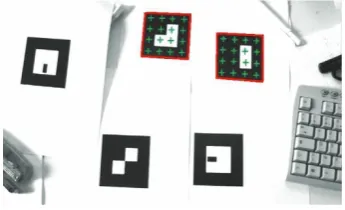
We present now, the experimental results and a detailed evaluation of different localization and tracking methods presented before. First, we test our visual tracking technique based on fiducial identification and pose estimation. The identification algorithm detects square targets in image and computes their codes, if this code matches with the template code prerecorded in the matching database file, then the target is identified and tracked in (Figure 9).
The pose estimation algorithm evaluation is performed by comparing our hybrid EKF method to the analytical algorithm and the EKF. The comparison between these algorithms is carried out according to 4 main criterions: execution time, reconstruction error, generalization error, and real distance estimation.
Our first analysis concerning time execution of different algorithms, shows that the analytical algorithm is the fastest method with 19.3994μs for one pose estimation. The hybrid EKF makes 112.2672μs to estimate the same pose and finally, 13530.3030μs are necessary for the EKF to determine pose parameters. So, in term of computation time, we can say that the analytical algorithm is better than the other methods unlike the EKF which is very slow and seems to be inappropriate for real-time applications.
For reconstruction error, we moved the camera around the target object, the 3 algorithms estimate the pose param-eters and we evaluate reconstruction error in the image. The 3 algorithms computed 1400 poses, the error is estimated by reprojecting the object model on the image. For each pose computation, we reproject the target model on the image and we measure the deviation between real target corners and the projected corners. FromFigure 10(a), we see that when the distance between fiducials belongs to [0.10, 0.45] m, the analytical method and the hybrid EKF present the lowest reconstruction error, the two algorithms are accurate and stable in this interval, over this interval the EKF is the most accurate estimator.
Image
Fiducial dentification Points of interest
3D virtual object overlay
Pose estimation
Tracking reset
≥4
<4
Points tracker Occultations
Figure8: Robust tracking diagram.
Figure9: Fiducials identification.
The hybrid EKF and the analytical method present the best performance in terms of generalization error. The overall error behavior for these two algorithms is stable and do not present jitter in images.
In order to evaluate camera-target distance errors of the different algorithms, we use a calibration robot-bench which moves in two directionsXandY (Figure 11). The camera is mounted on the robot bench, the target is fixed in the other side of the bench. This bench allows to control the motion of the robot and compare the distance with the estimated pose of different algorithms. We sample the robot displacement space in order to compute the corresponding pose with the different pose estimators. We have 1939 robot positions for which each algorithm estimates the pose parameters and computes the distance between the optical center of the camera and the target.
We have classified the obtained pose results into 10 classes and we computed the mean errors and variances of the pose estimation methods. The results are illustrated inFigure 12 to compare the generated errors of the real distance given by the robot (robot position) and the position estimated by the pose algorithms. We notice that the analytical method presents an important mean error compared to other methods, however, its variance is quite small. The hybrid EKF presents best performances unlike the EKF algorithm which presents a large variance around its mean error.
Figure 13represents real distances computed by the robot according to distance estimated by the different pose algo-rithms. Indeed, this evaluation determines, with accuracy, the distance error generated from each pose estimator. The interpretation of errors is performed by approximating the curves represented in Figure 13 with nonlinear regression for EKF and hybrid EKF and a quadratic regression for the analytical algorithm. The mean error of the analytical algorithm is 0.84% (a mean error of 8.4 mm for a distance of 1 m) while the EKF degenerates and presents a mean error of 2.6%. The best value of error is obtained with the hybrid EKF where it is estimated to 0.72%. We conclude that the hybrid EKF is best real distance estimator. Data are fitted using 1939 data points, inTable 1, the best values for each comparison criterion is highlighted in green, whereas the worst are the red ones.
Since the pose parameters were determined, we have projected a virtual cube on the detected real target in order to evaluate visually the virtual object rendering stability. In this experiment, the camera is freely moved around fiducials. The identification algorithm detects and track targets in frames and the hybrid EKF estimates position and orientation of the camera. We can see that virtual objects are well superimposed on the real image (Figure 14), and they remain laid on the target for different camera pose. These experimental tests proved the effectivness and the accuracy of the hybrid EKF.
The second part of the experiments evaluates the robust tracker. Figure 15 represents some camera images used during our experimental protocol. As we see in this figure, the targets are tracked even if they are not identified (visible points less than 4). The robust tracker handles occlusions, maintains the virtual cube overlaying and it is robust to change in illumination, scale, and orientation.
7. Discussion
0
R
ec
0.1 0.2 0.3 0.4 0.5 0.6
Distance between fiducials (m) Analytical algoritm
EKF Hybrid EKF
(a)
0 10 20
Gener
0.1 0.2 0.3 0.4 0.5 0.6
Distance between fiducials (m) Analytical algoritm
EKF Hybrid EKF
(b)
Figure10: (a) Reconstruction error according to distance between fiducials. (b) Generalization error according to distance between fiducials.
(a)
(b) (c)
Figure11: Robot bench used for distance evaluation.
Table1: Results on the different experiments performed for dis-tance estimation.
Algorithm Anal. algo. EKF H. EKF
Mean error (m) 0.0168 0.0030 0.0046 Variance 6.9574e−6 0.3567 3.6445e−6 Standard deviation 0.0026 0.5973 0.0019
Time (μs) 660 1894200 15680
are visible, they are tracked by the visual tracker. However, if a feature point of a target is occulted, the fiducial is
not detected anymore and this causes the tracking failure. Our robust method manages occlusions problem and tracks visible points to maintain virtual graphics overlaying when targets are not identified.
In addition, the used sequences consist of real scenes of the user environment. An attention is given to feature points detection, motion analysis, and robust matching of points during tracking.
0 0.005 0.01 0.015 0.02 0.025 0.03
Me
an
er
ro
r
(m
)
0.8 1 1.2 1.4 1.6
Distance camera—fiducial center (m) Analytical algoritm
EKF Hybrid EKF
(a)
0 0.005 0.01 0.015 0.02 0.025 0.03
Va
ri
an
ce
(m
)
0.8 1 1.2 1.4 1.6
Distance camera—fiducial center (m) Analytical algoritm
EKF Hybrid EKF
(b) Figure12: Mean errors and variances of the classified data.
0.6 0.8 1 1.2 1.4 1.6 1.8
M
easur
ed
distanc
e
(m)
0.8 1 1.2 1.4 1.6 1.8
Distance camera—fiducial center (m) Analytical algoritm
EKF Hybrid EKF
Figure 13: Evaluation of measured distances according to real distances.
We compared the performances of three pose estimation algorithms. We evaluated these methods using an experi-mental protocol to compute error sources and estimate the time execution. We used an iterative method depending on nonlinear optimization and a new analytical method based on direct computation of parameters. The main accomplishments of this comparison are.
(1) A new identification algorithm of coded fiducials. (2) A robust tracking method to handle targets
occlu-sion.
(3) A hybrid pose estimation algorithm based on a combination of analytical and iterative method.
(4) A comparison of different methods in term of exe-cution time, reconstruction errors and generalization errors.
We quantitatively analyzed the tracking and localization errors and we proposed a new method combining both numerical and analytical algorithm to overcome drawbacks of each method and enhance accuracy and robustness of our hybrid algorithm.
Indeed, the two kinds of algorithms have advantages and shortcomings. Iterative methods are accurate but suffer from computation expense due to bad initialization and local minima problems. On the other side, the analytical methods are fast but their major disadvantage is the lack of accuracy.We exploit the complementary nature of these two pose estimation methods to compensate for the weakness of each technique. Finally, the experimental results demonstrate the system’s effectiveness.
8. Conclusion
(a) (b) Frame 50
(c)
Frame 100
(d)
Figure14: Virtual object overlay in a tracking sequence using various fiducials.
(a) (b) (c)
(d) (e) (f)
system provides interesting solutions for camera localization using coded targets. Finally, our system was tested to manage augmentations in AR applications, the obtained results of overlaying were accurate.
Thereafter, we proposed an algorithm of feature points tracking based on object identification and pose com-putation. We showed how to extend this method and make it robust in presence of occlusions using the optical flow approach. The obtained tracking results were accurate and robust and showed the validity of our method. In perspective, we will combine the camera with an inertial measurement unit in order to locate this camera in case of total occlusion of all targets.
References
[1] B. Jiang, S. You, and U. Neumann, “Camera tracking for augmented reality media,” inProceedings of IEEE International Conference on Multimedia and Expo, pp. 1637–1640, 2000. [2] H. Araujo, R. Carceroni, and C. Brown, “A fully projective
formulation for Lowe’s tracking algorithm,” Tech. Rep. 641, University of Rochester, Rochester, NY, USA, 1996.
[3] J. J. More, “The levenberg-marquardt algorithm, implementa-tion and theory,” inProceedings of the Biennial Conference on Numerical Analysis, pp. 105–116, 1978.
[4] D. B. Gennery, “Tracking known three-dimensional objects,” inProceedings of the American Association of Artificial Intel-ligence (AAAI ’82), pp. 13–17, Pittsburgh, Pa, USA, August 1982.
[5] D. G. Lowe, “Robust model-based motion tracking through the integration of search and estimation,”International Journal of Computer Vision, vol. 8, no. 2, pp. 113–122, 1992.
[6] C. Harris, “Tracking with rigid models,” inActive Vision, A. Blake, Ed., Chapter 4, pp. 59–73, MIT Press, 1993.
[7] L. Naimark and E. Foxlin, “Circular data matrix fiducial system and robust image processing for a wearable vision-inertial self-tracker,” in Proceedings of IEEE International Symposium on Mixed and Augmented Reality (ISMAR ’02), pp. 27–36, Darmstadt, Germany, 2002.
[8] A. I. Comport, E. Marchand, and F. Chaumette, “A real-time tracker for markerless augmented reality,” inProceedings of the ACM/IEEE International Symposium on Mixed and Augmented Reality (ISMAR ’03), pp. 36–45, Tokyo, Japan, October 2003. [9] J. H. Chen, C. S. Chen, and Y. S. Chen, “Fast algorithm
for robust template matching with M-estimators,” IEEE Transactions on Signal Processing, vol. 51, no. 1, pp. 230–243, 2003.
[10] M. Maidi, F. Ababsa, and M. Mallem, “Robust fiducials tracking in augmented reality,” inProceedings of the 13th Inter-national Conference on Systems, Signals and Image Processing (IWSSIP ’06), pp. 423–42, Budapest, Hungary, 2006.
[11] H. Kato and M. Billinghurst, “Marker tracking and hmd calibration for a video-based augmented reality conferencing system,” inProceedings of the 2nd IEEE and ACM International Workshop on Augmented Reality (IWAR ’99), pp. 85–92, San Francisco, Calif, USA, 1999.
[12] J. Rekimoto and Y. Ayatsuka, “Cybercode: designing aug-mented reality environments with visual tags,” inProceedings of DARE 2000 on Designing Augmented Reality Environments (DARE ’00), pp. 1–10, Elsinore, Denmark, 2000.
[13] Y. Cho and U. Neumann, “Multi-ring color fiducial systems for scalable fiducial tracking augmented reality,” inProceedings of
IEEE Virtual Reality Annual International Symposium (VRAIS ’98), p. 212, Atlanta, Ga, USA, 1998.
[14] M. Fiala, “ARTag, a fiducial marker system using digital tech-niques,” inProceedings of IEEE Computer Society Conference on Computer Vision and Pattern Recognition (CVPR ’05), vol. 2, pp. 590–596, San Diego, Calif, USA, 2005.
[15] J. Y. Didier, F. Ababsa, and M. Mallem, “Hybrid camera pose estimation combining square fiducials localization technique and orthogonal iteration algorithm,”International Journal of Image and Graphics, vol. 8, no. 1, pp. 169–188, 2008.
[16] G. Welch and G. Bishop, “An introduction to the Kalman filter,” Tech. Rep. TR 95-041, Department of Computer Science, University of North Carolina, USA, 2004.
[17] B. D. Lucas and T. Kanade, “An iterative image registration technique with an application to stereo vision,” inProceedings of the DARPA Image Understanding Workshop, pp. 121–130, 1981.
[18] M. Maidi, F. Ababsa, and M. Mallem, “Active contours motion based on optical flow for tracking in augmented reality,” inProceedings of the 8th International Conference on Virtual Reality (VRIC ’06), pp. 215–222, Laval, France, 2006. [19] S. You, U. Neumann, and R. Azuma, “Hybrid inertial and
vision tracking for augmented reality registration,” in Proceed-ings of IEEE Virtual Reality (VR ’99), pp. 260–267, Houston, Tex, USA, 1999.
[20] L. Naimark and E. Foxlin, “Encoded LED system for optical trackers,” inProceedings of the 4th IEEE and ACM International Symposium on Symposium on Mixed and Augmented Reality (ISMAR ’05), pp. 150–153, Vienna, Austria, October 2005. [21] D. Stricker, G. Klinker, and D. Reiners, “A fast and robust
line-based optical tracker for augmented reality applications,” in
Proceedings of the 1st International Workshop on Augmented Reality (IWAR ’98), pp. 129–145, San Francisco, Calif, USA, 1998.