IJEDR1703068
International Journal of Engineering Development and Research (
www.ijedr.org
)
457
High Performance Cache Architecture Using Victim
Cache
Suyog S. Kandalkar1, Yogesh S. Watile2
1M.Tech student, Electronics & Communication, DMIETR, Wardha, India
2 Asst. Professor, Electronics & Communication, DMIETR, Wardha, India.
________________________________________________________________________________________________________
Abstract: A CPU is consist of various types of memory. Microprocessor is the first and the leading component of the CPU. With the increasing speed of modern microprocessors, the operating speed of different memories becomes more critical to the system performance. The increasing speed gap between the processors and memories can be matched or adjusted with the help of cache memory. Cache memory are on-chip memory element used to store data. Cache memory is used to increase data transfer rate. The performance of a cache is calculated by its ability of differentiate and maintaining the data that the program will need in near future and unwanted data will be discarded. This can be understood through replacement policy of the cache controller. A cache controller is used for tracking generated miss rate in cache memory. While using direct mapping technique in cache, there is a fixed cache location for any given block. But due to that two different blocks can map into the same line and the hit ratio will be low. With fully associative mapping, there is flexibility to replace block when a new block read into cache. This review paper proposed the technique this technique is very useful to reduce the miss rate in cache memory. In the proposed technique the direct mapped cache is added with a small associative cache known as victim cache. A line removed from the direct mapped is temporarily store in the victim cache.
Keywords: Cache memory, Victim cache, Cache controller.
________________________________________________________________________________________________________
I.
INTRODUCTIONIn CPU, cache used by the central processing unit (CPU) of a computer to reduce the average time to access data from the main memory. A cache is a smaller, faster memory, closer to a processor core, which stores copies of the data from frequently used main memory locations. Most CPUs have different independent caches, including instruction and data caches, where the data cache is usually organized as a hierarchy of more cache levels (L1, L2, etc.). When the processor needs to read from or write to a location in main memory, it first checks whether a copy of that data is in the cache. If so, the processor immediately reads from or writes to the cache, which is much faster than reading from or writing to main memory.
Cache memory is used to increase data transfer rate. Generally it is difficult to found data requested by microprocessor in cache memory, as the size of cache memory is very small as compared to RAM and main memory. When any data requested by microprocessor will not found in cache memory this causes cache miss in cache memory. We know that cache memory is on chip memory, if data requested by microprocessor is found in cache memory then it will increase the data transfer rate as data is present nearer to processor. If data requested by microprocessor is not found in cache memory, then data will receive by microprocessor from RAM or main memory. It takes more time for this process and it directly affects the data transfer rate. This means that speed or data transfer rate increase by reducing the cache miss in cache memory. To track the cache miss in cache memory we will design cache controller, which will help us to increase data transfer rate between main memory and processor. In design of a cache, parameters that enable design of various cache architectures include the overall cache size, block size and efficiency, along with the replacement policy employed by the cache controller. The proposed architecture takes advantage of a number of extra victim lines that can be associated with cache sets that experience more conflict misses, for a given program. To reduce the miss delay in caches, the concept of victim cache is proposed. To implement the proposed cache architecture, three modules are considered; a cache controller, and two storage modules for the data store and the TAG store. This is illustrated in Fig. below. The cache controller handles the memory access requests from the processor, and issues control signals to control flow of data within the cache [1].
IJEDR1703068
International Journal of Engineering Development and Research (
www.ijedr.org
)
458
Fig 1: System Block Diagram [1]II.
LITERATURE REVIEWThis paper propose the ever increasing density and performance of FPGAs, has increased the importance and popularity of soft processors. The growing gap between the speed of processors and memories can partly be compensated through memory hierarchy. Since memory accesses follow a non-uniform distribution, and vary from one application to another, variable set-associative cache architectures have emerged. In this paper, a novel cache architecture, primarily aimed at soft processors, is proposed to address the variable access demands of applications, through dynamically configurable line-associativity, with no memory overhead. This proposed paper apply their system for increase the speed of the system [1].
This paper proposed the that, Recent trends of CMOS scaling and use of large last level caches (LLCs) have led to significant increase in the leakage energy consumption of LLCs and hence, managing their energy consumption has become extremely important in modern processor design. The conventional cache energy saving techniques require offline profiling or provide only coarse granularity of cache allocation. They present FlexiWay, a cache energy saving technique which uses dynamic cache reconfiguration. FlexiWay logically divides the cache sets into multiple modules and dynamically turns off suitable and possibly different number of cache ways in each module. FlexiWay has very small implementation overhead and it provides fine -grain cache allocation even with caches of typical associativity, e.g. an 8-waycache, this paper proposed the technique for divides the cache sets into multiple [2].
This paper proposed the Customizing caches has until recently been restricted to core-based flows, in which a new chip will be fabricated. However, several configurable cache architectures have been proposed recently for use in pre-fabricated microprocessor platforms. Tuning those caches to a program is still however a cumbersome task left for designers, assisted in part by recent computer-aided design (CAD) tuning aids. They propose to move that CAD on-chip, which can greatly increase the acceptance of configurable caches. They introduce on-chip hardware implementing an efficient cache tuning heuristic that can automatically, transparently, and dynamically tune the cache to an executing program. They carefully designed the heuristic to avoid any cache flushing, since flushing is power and performance costly [3].
This paper proposed the Direct-mapped caches are a popular design choice for high performance processors unfortunately, direct-mapped caches suffer systematic interference misses when more than one address maps into the same cache set. This paper describes the design of column-associative caches. Which minimize the conflicts that arise in direct-mapped accesses by allowing conflicting addresses to dynamically choose alternate hashing functions, so that most of the conflicting data can reside in the cache. At the same time, however, the critical hit access path is unchanged. The key to implementing this scheme efficiently is the addition of a rehash bit to each cache set which indicates whether that set stores data that is referenced by an alternate hashing function. When multiple addresses map into the same location, these rehashed location are preferentially replaced. Using trace-driven simulations and an analytical model, we demonstrate that a column-associative cache removes virtually all interference misses for large caches, without altering the critical hit access time [4].
IJEDR1703068
International Journal of Engineering Development and Research (
www.ijedr.org
)
459
performed selectively [5].This paper proposed that, Victim caching was proposed by Jouppi as an approach to improve the miss rate of direct-mapped caches. This approach augments the direct-mapped main cache with a srnall fully-associate cache, called victim cache that stores cache blocks evicted from the main cache as a result of replacements. Author propose and evaluate an improvement of this scheme, called selective victim caching. In this scheme, incoming blocks into the first-level cache are placed selectively in the main cache or the victim cache by the use of a prediction scheme based on their past history of use. In addition, interchanges of blocks between the main cache and the victim cache are also performed selectively. Author show that the scheme results in significant improvements in miss rate as well as the number of interchanges between the two caches, for both small and large caches (4 Kbytes ~ 128 Kbytes). [6].
III.
CACHE MEMORY
Now a days computers are designed to operate with different types of memory organized in a memory hierarchy. In such memory hierarchies, as the distance of the memories increases from the processor, as the distance from the processor increases, so that the access time for each memory increases. Closest to the CPU is the Cache Memory. Cache memory is fast but quite small; it is used to store small amounts of data that have been accessed recently and are likely to be accessed again soon in the future. Data is stored here in blocks, each containing a number of words. To keep track of which blocks are currently stored in Cache, and how they relate to the rest of the memory, the Cache Controller stores identifiers for the blocks currently stored in Cache. These include the index, tag, valid and dirty bits, associated with a whole block of data. To access an individual word inside a block of data, a block offset is used as an address into the block itself. Using these identifiers, the Cache Controller can respond to read and write requests issued by the CPU, by reading and writing data to specific blocks, or by fetching or writing out whole blocks to the larger, slower Main Memory. Figure 2 shows a block diagram for a simple memory hierarchy consisting of CPU, Cache (including the Cache controller and the small, fast memory used for data storage), Main Memory Controller and Main Memory proper.
Fig. 2: Memory Hierarchy Block Diagram [8]
When the processor request data, the cache checks to see if that address is present in cache memory or not, if address present in cache then cache hit occurs else it will cache miss. If the cache contains the memory location, then the cache hit occurs. If the cache does not contain the memory location, then the cache miss occurs.
Cache Organization
IJEDR1703068
International Journal of Engineering Development and Research (
www.ijedr.org
)
460
In cache organization the main memory is divided into pages which are known as cache pages, where the size of cache pages is equal to the size of cache memory. Further cache pages are divided into cache lines.Fully-Associative
This scheme allows any line in main memory to be stored at any location in cache. Fully associative cache does not use cache pages it use only cache lines. Main memory and cache memory are both divided into lines of equal size. Any cache line may store any memory line, hence the name fully associative.
Fig. 4: Fully Associative cache [8]
Direct Map
Fig. 5: Direct Mapped Cache [8]
In this scheme main memory is divided into cache page. Direct map cache may only store a specific line of memory within the same line of cache. This scheme directly maps a memory line, hence the name direct mapped cache.
IV.
VICTIM CACHECache memory is extremely fast memory that is built into a computer’s central processing unit (CPU), or located next to it on a separate chip. The CPU uses cache memory to store instructions that are repeatedly required to run programs, improving overall system speed.
IJEDR1703068
International Journal of Engineering Development and Research (
www.ijedr.org
)
461
Fig 6: Memory hierarchy for the victim caching scheme.[5]Figure 6 is a simple block diagram illustrating the location of the victim cache in the overall memory hierarchy. The victim cache can be considered to be part of the L1 cache system. The next lower level of the memory hierarchy can be an L2 cache or the main memory
The first-level (Ll) cache consists of a direct-mapped main cache and a small fully-associative victim cache. A line buffer is included so that sequential accesses to words in the same cache block (line) do not result in more than one access to the cache, thus preventing repeated updates of state bits in cache. Upon the first access to a cache line, the entire line is brought into the line buffer in parallel with the execution in the CPU; subsequent accesses to words in the same line are satisfied from the line buffer and cause no update of state bits in cache. Lines are replaced in the victim cache according to the LRU (least recently used) algorithm. The next lower level of the memory hierarchy can be main memory. On every memory access, the line buffer, main cache, and the victim cache are searched in parallel. If the line is found in the line buffer, the instruction is fetched from there and no other action is necessary. Otherwise, three different cases must be considered:[5]
1. Hit in main cache: If the word is found in the direct-mapped cache, it is delivered to the CPU and the entire line containing the accessed word is brought into the line buffer.
2. Miss in main cache, hit in victim cache: In this case, the word is fetched from the victim cache into the line buffer and forwarded to the CPU.
3. Miss in both main and victim caches: If the word is not found both in the main cache and the victim cache, it must be fetched from the next level of the hierarchy.
Cache Hits: When the cache contains the information requested, the transaction is said to be a cache hit.
Cache Miss:When the cache does not contain the information requested, the transaction is said to be a cache miss.
Fig. 7: Victim Cache Operation [5]
IJEDR1703068
International Journal of Engineering Development and Research (
www.ijedr.org
)
462
the L1 cache and the victim cache at the same time. There are two cases to consider for managing the movement of data between the two caches:Case 1: Processor reference to memory misses in both the L1 cache and the victim cache.
a. The required block is fetched from main memory (or the L2 cache if present) and placed into the L1 cache.
b. The replaced block in the main cache is moved to the victim cache. There is no replacement algorithm. With a direct-mapped cache, the line to be replaced is uniquely determined.
c. The victim cache can be viewed as a FIFO queue or, equivalently, a circular buffer. The item that has been in the victim cache the longest is removed to make room for the incoming line. The replaced line is written back the main memory if it is dirty ( has been updated).
Case 2: Processor reference to memory misses the direct-mapped cache but hits the victim cache. a. The block in the victim cache is promoted to the direct-mapped cache.
b. The replaced block in the main cache is swapped to the victim cache [5].
V.
CACHE CONTROLLERCache controller work on predictability by taking the advantage of cache memory output. To design the cache controller various replacement policies can be used like FIFO, LRU, etc. Cache controller is used to track the cache miss induced in cache memory. When any address requested by microprocessor is not found in cache memory then cache miss will occur. Once the cache miss detect with the help of cache memory then cache controller will tracks the induced cache miss. If cache hit occurs then it will keep the older address same until the cache miss will occurs.
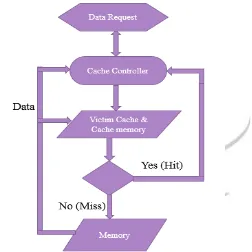
Fig. 8: Cache Controller Flow Chart
VI.
IMPLEMENTATIONIJEDR1703068
International Journal of Engineering Development and Research (
www.ijedr.org
)
463
Fig: 9 Implementation of the proposed cache[1]VII.
STRUCTURE OF MEMORYFig 10: Cache Structure [1]
The structure of the proposed cache architecture is shown in Fig., which contains both the L1 cache and the victim cache associated with it. The data memory includes the data memory of the L1 cache (cache DATA) and that of the victim cache (V-DATA), accessed when the HIT or the VHIT (victim HIT) signals are asserted, respectively. The TAG storage in this architecture consist of two parts; the TAG memory and the V-TAG memory. Each word of the TAG memory is dedicated to one set in the L1 cache. The V-TAG (victim TAG) memory is the TAG storage part of the victim cache that stores the tag label of each victim data, and has a VALID bit to check the validity of the data currently stored in the corresponding data store line of the victim cache. [1]
IJEDR1703068
International Journal of Engineering Development and Research (
www.ijedr.org
)
464
VIII.
SYSTEM ARCHITECTUREThe victim cache contains fourteen cache lines worth of information, is fully-associative, and uses a FIFO (first in, first out) replacement policy. The reason for using FIFO instead of random as the first level cache is that random replacement is more effective for larger cache sizes. The small size of the victim cache makes it probable that certain cache blocks will be replaced more often. Because the victim cache outputs to the DRAM on a cache miss, replacing blocks on a more frequent basis will result in a higher Average memory aces time. A FIFO replacement policy ensures each block has the same chance to be replaced. For example let’s consider cache system of two levels. Let level one cache be victim cache. Let the direct mapped cache module be sixteen sets. The fully associative cache module is four blocks. Let the line size be one byte. Let the address trace 4, 20, 4, 20, 36, 52. These addresses map to set four in the direct mapped cache of victim cache. The following happens in victim cache algorithm.
1. Address 4 is put in set 4 of direct mapped cache.
2. Address 20 is put in set 4 of direct mapped cache pushing address 4 to fully associative cache. 3. Address 4 is hit in fully associative cache swapped with address 20 of direct mapped cache. 4. Address 20 is hit in fully associative cache swapped with address 4 of direct mapped cache.
5. Address 36 replaces address 20 in direct mapped cache pushing address 20 to fully associative cache 6. Address 52 is replaces in direct mapped cache pushing address 36 to fully associative cache.
During above cache mapping, all four blocks of fully associative cache are searched for addresses 20, 4, 20, 36, 52 giving eighteen fully associative cache address match. There are two hits in the above trace.
IX.
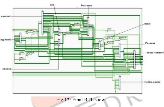
RTL VIEW OF PROPOSED SYSTEMFig 12: Final RTL view
Muxes are used to select which cache block to output and where to output (first level cache or memory). To avoid losing the cache data while swapping the two cache lines, additional cache registers are added to hold the output from the first level cache and victim cache. Register bank is used to store the data temporary while swapping the cache lines with victim lines. In addition to sending data back to the first level cache, the victim cache must also send the dirty bit. The first level cache needs to know whether the data being sent up is dirty or not, so the correct replacement behavior is used on subsequent memory accesses. To handle the interrupt signal and pause signal control section is used. And to handle all read write operation and other control signals the memory control unite is used. Pc-next is used to track the next address which is to be fetched by controller it track the address range for controller.
X.
SIMULATION RESULTSIJEDR1703068
International Journal of Engineering Development and Research (
www.ijedr.org
)
465
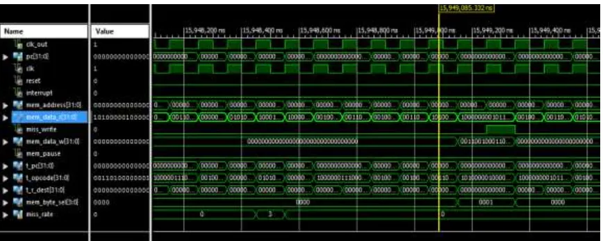
Fig 13: Cache Controller simulationXI.
CONCLUSIONThe system is designed to reduce the miss rate. To design the proposed system, first of all the cache memory is to be designed. Cache is the small memory whose function is to provide the required data to the CPU.After designing the cache memory, controller for cache memory is to be designed so as to control the data transfer made by memory.The improvement to the present architecture is done by adding the concept of victim cache into the present cache memory i.e. victim cache memory is not a separate memory but it is the part of cache memory. Victim cache is again a small memory which is even smaller than cache memory. A victim cache is a fully associative cache that holds data recently used from the main cache. The use of victim cache increases the performance of cache memory by reducing miss’s occurred during operation. Such an approach would be of great utility to many modern embedded applications.
REFERENCES
[1] Mehrdad Biglari, Kamyar Barijough, Maziar Goudarzi, Behnaz Pourmohseni “A Fine-Grained Configurable Cache Architecture for Soft Processors”, In 2015 18th CSI International Symposium on Computer Architecture and Digital Systems (CADS).
[2] M. Z. Zhao, and J. S. Vetter, “FlexiWay: A Cache Energy Saving Technique using Fine-grained Cache Reconfiguration”, In 31st IEEE International Conference on Computer Design, pp. 100-107, 2013.
[3] C. Zhang, F. Vahid and R. Lysecky, "A Self-Tuning Cache Architecture for Embedded Systems", In Conference Proceedings of Design, Automation, and Test in Europe, pp. 142-147, 2004.
[4] A. Agrawal, and S. D. Pudar, “Column-associative Caches: a Technique for Reducing the Miss Rate of Direct-mapped Caches”, In 20th Annual International Symposium on Computer Architecture, pp. 179-190, 1993.
[5] William Stallings: APPENDIX D VICTIM CACHE STRATEGIES, Computer Organization and Architecture, Ninth Edition Prentice Hall 2012 ISBN: 013293633X.
[6] Dimitrios Stiliadis, Anujan Varma, “Selective Victim Caching: A Method to Improve the Performance of Direct-Mapped Caches” In Proceedings of the Twenty-Seventh Annual Hawaii International Conference on System Sciences, 1994.
[7] Jouppi, N. "Improving Direct-Mapped Cache Performance by the Addition of a Small Fully-Associative Cache and Prefetch Buffers."Proceedings, 17th Annual International Symposium on ComputerArchitecture, May 1990.
[8] COE758 – Digital Systems Engineering, Project #1 – Memory Hierarchy: Cache Controller
[9] S. Subha ‘An Architecture for Victim Cache’ International Conference on Advances in Electrical, Electronics, Information, Communication and Bio-Informatics (AEEICB16).
[10] PG031 April 24, 2012System Cache v1.00.a www.xilinx.com.
![Fig 1: System Block Diagram [1]](https://thumb-us.123doks.com/thumbv2/123dok_us/8208627.1371456/2.596.187.408.60.249/fig-system-block-diagram.webp)
![Fig. 2: Memory Hierarchy Block Diagram [8]](https://thumb-us.123doks.com/thumbv2/123dok_us/8208627.1371456/3.596.218.388.603.772/fig-memory-hierarchy-block-diagram.webp)
![Fig. 4: Fully Associative cache [8]](https://thumb-us.123doks.com/thumbv2/123dok_us/8208627.1371456/4.596.177.450.154.521/fig-fully-associative-cache.webp)
![Fig. 7: Victim Cache Operation [5]](https://thumb-us.123doks.com/thumbv2/123dok_us/8208627.1371456/5.596.50.530.377.752/fig-victim-cache-operation.webp)
![Fig 10: Cache Structure [1]](https://thumb-us.123doks.com/thumbv2/123dok_us/8208627.1371456/7.596.134.485.297.544/fig-cache-structure.webp)